Mircom BPS-1100 Signal Booster Power Supply
Description
Mircom’s BPS-1100 Signal Booster Power Supply is designed to extend the power capabilities of existing indicating circuits and to provide power for other ancillary devices. The BPS-1100 may be connected to any ULC Listed Fire Alarm Control Panel to provide indicating circuit expansion.
The BPS-1100 consists of four indicating circuits, which can be expanded up to twelve with the addition of two SGM-1004A Four Indicating Circuit Module. Each indicating circuit is rated at 1.7 Amp maximum with a total output capacity of 11 Amps. The outputs may be configured as four Class A/B (Style Z/Y).
The BPS-1100 will also support additional relay circuits with the addition of the RM-1008A Eight Relay Circuit Module. The RM-1008A is normally used for interconnecting multiple BPS-1100 units.
Mircom’s BPS-1100 provides four supervised programmable contact inputs, trouble and local ground detection output contacts and support for supervised and non-supervised suite isolators.
Features
- Four 4 Class A/B (Style Z/Y) Indicating Circuits with individual trouble indicators (1.7 Amps max. per circuit)
- Each Indicating Circuit can be configured as Steady, Temporal Code, California Code or March Time Alert
- Four supervised programmable contact inputs
- Indicating Circuits may be individually disconnected by a DIP switch
- Auxiliary relay contacts for Booster Ground
Fault and Common Trouble (Each relay contact Form C, 28 VDC @ 1 Amp (resistive)) - Easy configuration via push buttons and DIP switches on the front panel
- Extensive Transient Protection
- 11 Amp maximum unregulated output
- Supports supervised and non-supervised suite isolator
- Indicating circuits can be expanded up to twelve with two SGM-1004A
- Regulated auxiliary 24VDC Output (1.7 Amp)
- Space for 6 to 17 AH battery
The indicating circuits on the BPS-1100 can be configured for Alarm (Silence able), Evacuation 2nd Stage (Silence able) or Strobe (Non-Silence able) and correlated to the programmable contact inputs
The indicating circuits can be configured for the following audible signal rates: Steady, Temporal Code, California Code or March Time Alert.
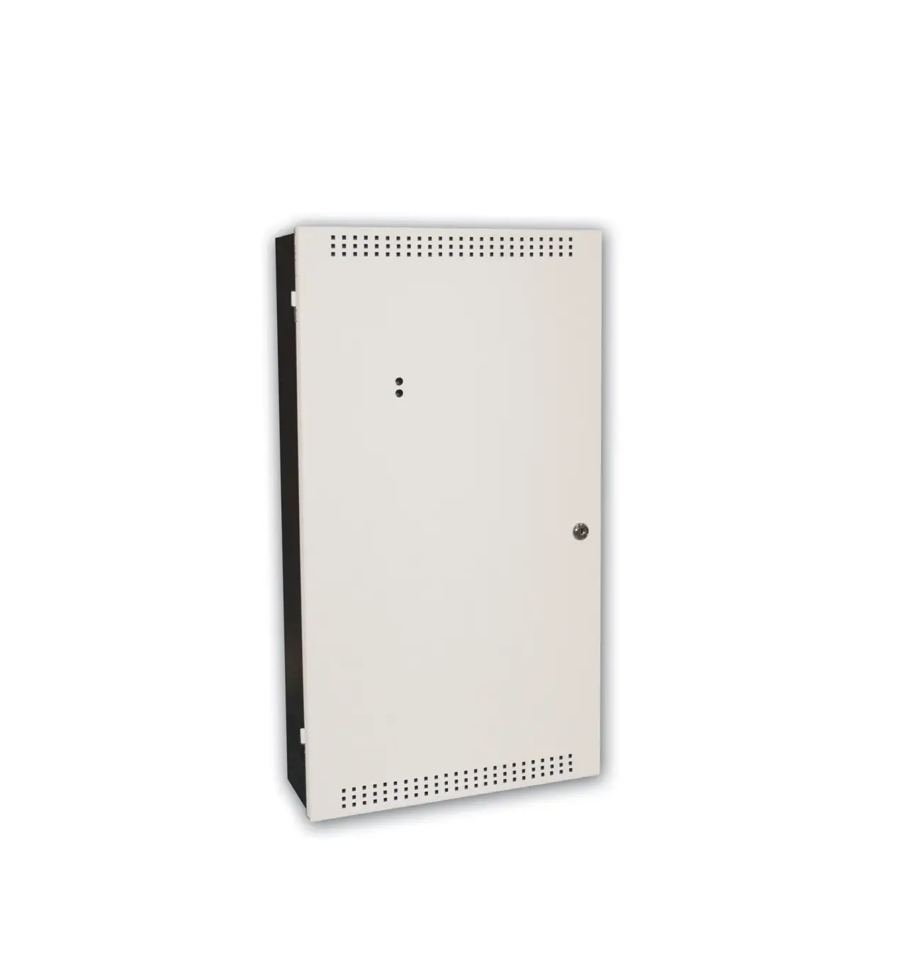
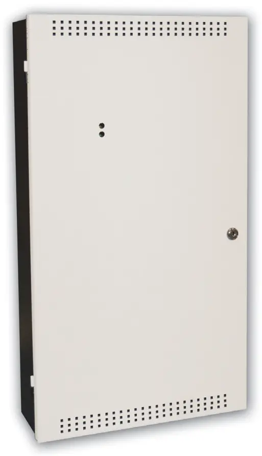
The BPS-1100 is enclosed in a beige colour cabinet and comes with a durable CAT-30 lock and key. The BPS-1100 contains its own battery charger capable of charging up to 17 AH batteries. The cabinet provides space to mount up to 17 AH Gel Cell batteries.
Specifications
- AC Line Voltage: 120V, 60Hz / 240V, 50Hz 2 Amps / 1Amp (primary)
- Power Supply Ratings: 12 Amps. max. (secondary)
- For Indicating Circuits: 24VDC unfiltered, 11 Amps. max.
- Battery: 24VDC, Gel-Cell/Sealed Lead-Acid
- Charging Capability: 10-17 AH batteries
- Current Consumption: Standby: 200 mA, Alarm: 350 mA
- Cabinet Dimensions: 26”H x 14½”W x 4½”D
- Battery Space: Up to two 17 AH batteries
- Auxiliary Relays: (resistive loads) Common Ground: Form C, 1 Amp, 28 VDC Common Trouble: Form C, 1 Amp, 28 VDC
Ordering Information
Model Description
BPS-1100 Signal Booster Power Supply
Adder Modules
SGM-1004A Four Class A/B (Style Z/Y) Indicating Circuit Module (Rated at 1.7 Amps per circuit)
RM-1008A Eight Relay Circuit Module (Form C relays rated for 28 VDC @ 1 Amp. max. per circuit)
Customer Support
Canada
25 Interchange Way
Vaughan, Ontario L4K 5W3
Telephone: (905) 660-4655
Fax: (905) 660-4113
U.S.A.
4575 Witmer Industrial Estates
Niagara Falls, NY 14305
Toll Free: (888) 660-4655
Fax Toll Free: (888) 660-4113
Web page: http://www.mircom.com
Email: [email protected]