![]() HMS-1FL Series Horizontal Multi Stage Jet Pumps
HMS-1FL Series Horizontal Multi Stage Jet Pumps
Owner’s Manual OWNERS MANUAL
Horizontal Multi-Stage Jet Pumps
“HMS-1FL” Series
MODELS
| 3/4 HP | 1 HP | 1-1/2 HP |
| HMSD-1FL | HMSE-1FL | HMSF-1FL |
293 WRIGHT STREET, DELAVAN, WI 53115 WWW.STA-RITE.COM
PH: 888-782-7483
© 2012 Pentair, Inc. All Rights Reserved.
California Proposition 65 Warning
![]() WARNING This product and related accessories contain chemicals known to the State of California to cause cancer, birth defects or other reproductive harm.
WARNING This product and related accessories contain chemicals known to the State of California to cause cancer, birth defects or other reproductive harm.
Deep Well Installation![]() Under certain conditions, horizontal multistage pumps can develop extremely high pressure. Install a pressure relief valve capable of passing entire pump flow at 75 PSI.
Under certain conditions, horizontal multistage pumps can develop extremely high pressure. Install a pressure relief valve capable of passing entire pump flow at 75 PSI.![]() Do not allow pump, pressure tank, piping, or any other system component containing water to freeze.
Do not allow pump, pressure tank, piping, or any other system component containing water to freeze.
Freezing may damage system, leading to injury or flooding. Allowing pump or system components to freeze will void warranty.
NOTICE: Support pump base to avoid strain on casing adapter or pump. Lack of support can damage adapter or pump.
Figure 2 shows casing adapter bolted directly to pump body.
Shallow Well Installation
NOTICE: If no foot valve is used, install 1” check valve in horizontal line.
Priming the Deep Well Pump
To prime pump, completely close the priming valve located just below the suction opening by turning screw clockwise. This valve will be left closed during operation in a deep well installation. See Figure 1.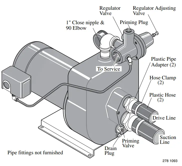 Figure 1 – Deep Well Installation
Close regulator adjusting valve, located on end of regulator, by turning stem clockwise. See Figure 1.
Remove priming plug from top of regulator valve. Fill with clean water. Replace plug. See Figure 1.
Start pump and run a few moments.
If pressure does not build up, remove priming plug and refill with more water. All of the trapped air in pump body was not removed.
Restart pump.
When pump is completely primed and builds up pressure, slowly open the regulator valve, (turn counter-clockwise), and observe the pressure reading on the pressure gauge.
When the pump reaches a point where it will lose prime, cavitation noise can be heard.
The best, or correct, pressure gauge setting is approximately 3 pounds higher than the pressure gauge reading was when the pump started to lose prime.
If pump loses prime, repeat the priming procedure above and this time open regulator valve only until the correct pressure reading is reached.
If a vacuum gauge is available, screw it into the 1/8” AVC tapping on front of tank body. Adjust regulator until 20” of vacuum is registered on the gauge. Tighten locknut on
regulator. This method will give maximum performance of the unit.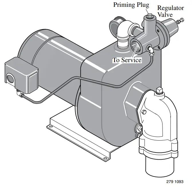 Figure 2 – Well Casing Adapter bolted directly to pump
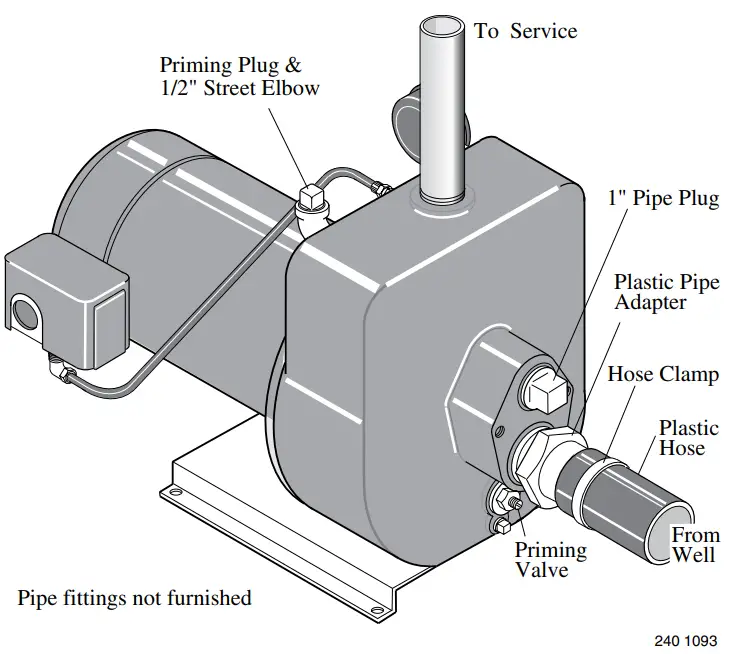 Figure 3 – Shallow Well Installation
HMSC pumps come equipped with pressure switch set to operate within a 20-40 PSI range. HMSD, HMSE, and HMSF pumps have 30-50 PSI pressure switches. When pump is used with precharged tank in system, set tank pre-charge at 18 PSI with a 20-40 PSI switch; set tank precharge at 28 PSI with a 30-50 PSI switch. Check tank precharge annually with an ordinary tire gauge. Pre-charge is set with no water pressure on system.
Priming the Shallow Well Pump![]() CAUTION Never run pump dry. Running pump without water may cause pump to overheat, damaging seal and possibly causing burns to persons handling pump. Fill pump with water before starting.
CAUTION Never run pump dry. Running pump without water may cause pump to overheat, damaging seal and possibly causing burns to persons handling pump. Fill pump with water before starting.![]() WARNING Never run pump against closed discharge.
WARNING Never run pump against closed discharge.
To do so can boil water inside pump, causing hazardous pressure in unit, risk of explosion and possibly scalding persons handling pump.
To prime the pump, completely open the priming valve located just below the suction opening on the tank body by turning the valve stem counter-clockwise all the way until it stops.
This valve may be left open during operation as a shallow well pump with no jet. See Figure 3 and “NOTICE” below.
Remove priming plug from top of elbow (see Figure 3), and fill with clean water. Replace plug.
Start pump and between 45-60 seconds. If water is not being pumped, turn off pump and repeat priming process.
NOTICE: If a bolt-on jet is being used, after pump is primed, close the priming valve during operation as a shallow well pump.
Service – Draining for Winter![]() CAUTION Do not touch an operating motor.
CAUTION Do not touch an operating motor.
Modern motors are designed to operate at high temperatures. To avoid burns when servicing pump, allow it to cool for 20 minutes after shut-down before handling. When the pump is to be disconnected from service, or is in danger of freezing, it should be drained. The pump has a drain plug which must be removed. Remove the priming plug to vent the pump.
If pump and motor are damaged due to freezing, the Warranty is void.
TABLE I
Recommended Fusing and Wiring Data – 60 Cycle Motors
| MOTOR HP | VOLTS | MAX. LOAD AMPERES | BRANCH FUSE* RATING AMPS | DISTANCE IN FEET FROM MOTOR TO METER | ||||
| 0′ to 100′ | 101′ to 200′ | 201′ to 300′ | 301′ to 400′ | 401′ to 500′ | ||||
| WIRE SIZE | ||||||||
| 3/4 | 115 | 15. | 20 | 12 | 8 | 6 | 6 | 4 |
| 3/4 | 230 | 7. | 15 | 14 | 14 | 14 | 12 | 10 |
| 1 | 115 | 19. | 25 | 10 | 8 | 6 | 4 | 4 |
| 1 | 230 | 10. | 15 | 14 | 14 | 12 | 10 | 10 |
| 1-1/2 | 115 | 24.0 | 30 | 10 | 6 | 6 | 4 | 3 |
| 1-1/2 | 230 | 12.0 | 15 | 14 | 14 | 12 | 10 | 10 |
*Fusetrons are recommended instead of fuses on all motor circuits.
Electrical
![]() Disconnect power before working on pump, motor, pressure switch, or wiring.
Disconnect power before working on pump, motor, pressure switch, or wiring.
MOTOR SWITCH SETTINGS
Your motor terminal board (located under the motor end cover) should look like one of those below. If the motor can operate at either 115 or 230 volts, it is set at the factory to 230 volts. Do not change motor wiring if line voltage is 230 volts, or if you have a single voltage motor.![]() CAUTION Never wire a 115 volt motor to a 230 volt line.
CAUTION Never wire a 115 volt motor to a 230 volt line.
Plug Type Voltage Selector Figure 4: Voltage set to 230 volts, Plug Type
Voltage is factory set to 230 volts. To change to 115 volts:
- Make sure power is off.
- Pull the voltage change plug off of the tabs.
- Move the voltage change plug to the 115 volt position. The plug will now cover 2 metal tabs and the arrow on the plug will line up with the 115V arrow on the label (see Figure 5).
 Figure 5: Voltage set to 115 volts, Plug Type
 - Attach the incoming power leads to the two outer screws on the pressure switch as shown in Figure 4.
- Attach the ground wire to one of the grounding connections, shown in Figure 4.
- If there are other wires, they should be capped.
- Reinstall the Motor end cover.
 Figure 6: Voltage set to 230 volts, Dial Type
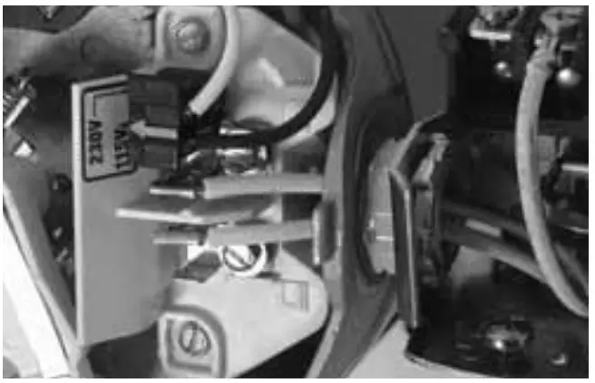 Figure 5: Voltage set to 115 volts, Plug Type
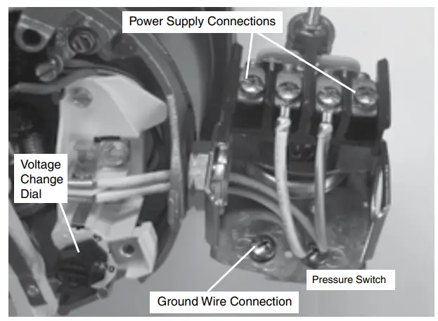 Figure 6: Voltage set to 230 volts, Dial Type
Dial Type Voltage Selector
Voltage is factory set to 230 volts. To change to 115 volts:
- Make sure power is off.
- Turn the dial counter-clockwise until 115 shows in the dial window as shown in Figure 7.
 Figure 7: Voltage set to 115 volts, Dial Type
 - Attach the incoming power leads to the two outer screws on the pressure switch as shown in Figure 6.
- Attach the ground wire to the grounding connections as shown in Figure 6.
- If there are other wires, they should be capped.
- Reinstall the Motor end cover.
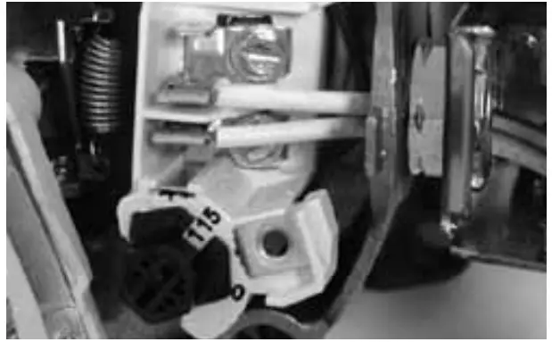 Figure 7: Voltage set to 115 volts, Dial Type
![]() WARNING Hazardous voltage. Can shock, burn, or kill. Connect ground wire before connecting power supply wires. Use the wire size (including the ground wire) specified in the wiring chart. If possible, connect the pump to a separate branch circuit with no other appliances on it.
WARNING Hazardous voltage. Can shock, burn, or kill. Connect ground wire before connecting power supply wires. Use the wire size (including the ground wire) specified in the wiring chart. If possible, connect the pump to a separate branch circuit with no other appliances on it.![]() WARNING Explosion hazard. Do not ground to a gas supply line.
WARNING Explosion hazard. Do not ground to a gas supply line.
WIRING CONNECTIONS![]() WARNING Fire hazard. Incorrect voltage can cause a fire or seriously damage the motor and voids the warranty. The supply voltage must be within ±10% of the motor nameplate voltage.
WARNING Fire hazard. Incorrect voltage can cause a fire or seriously damage the motor and voids the warranty. The supply voltage must be within ±10% of the motor nameplate voltage.
NOTICE: Dual-voltage motors are factory wired for 230 volts.
If necessary, reconnect the motor for 115 volts, as shown. Do not alter the wiring in single voltage motors.
Install, ground, wire, and maintain your pump in compliance with the National Electrical Code (NEC) or the Canadian Electrical Code (CEC), as applicable, and with all local codes and ordinances that apply. Consult your local building inspec- tor for code information.
Connection Procedure:
- Connect the ground wire first as shown in Figure 4. The ground wire must be a solid copper wire at least as large as the power supply wires.
- There must be a solid metal connection between the pressure switch and the motor for motor grounding protection.
If the pressure switch is not connected to the motor, connect the green ground screw in the switch to the green ground screw under the motor end cover. Use a solid
copper wire at least as large as the power supply wires. - Connect the ground wire to a grounded lead in a service panel, to a metal underground water pipe, to a metal well casing at least ten feet (3M) long, or to a ground electrode provided by the power company or the hydro authority.
- Connect the power supply wires to the pressure switch as shown in Figure 4.
Limited Warranty
STA-RITE warrants to the original consumer purchaser (“Purchaser” or “You”) of the products listed below, that they will be free from defects in material and workmanship for the Warranty Period shown below.
| Product | Warranty Period |
| Water Systems Products — jet pumps, small centrifugal pumps, submersible pumps and related accessories | whichever occurs first: 12 months from date of original installation, or 18 months from date of manufacture |
| Pro-Source™ Composite Tanks | 5 years from date of original installation |
| Pro-Source™ Steel Pressure Tanks | 5 years from date of original installation |
| Pro-Source™ Epoxy-Lined Tanks | 3 years from date of original installation |
| Sump/Sewage/Effluent Products | 12 months from date of original installation, or 18 months from date of manufacture |
Our warranty will not apply to any product that, in our sole judgement, has been subject to negligence, misapplication, improper installation, or improper maintenance. Without limiting the foregoing, operating a three phase motor with single phase power through a phase converter will void the warranty. Note also that three phase motors must be protected by three-leg, ambient compensated, extra-quick trip overload relays of the recommended size or the warranty is void.
Your only remedy, and STA-RITE’s only duty, is that STA-RITE repair or replace defective products (at STA-RITE’s choice). You must pay all labor and shipping charges associated with this warranty and must request warranty service through the installing dealer as soon as a problem is discovered. No request for service will be accepted if received after the Warranty Period has expired. This warranty is not transferable.
STA-RITE SHALL NOT BE LIABLE FOR ANY CONSEQUENTIAL, INCIDENTAL, OR CONTINGENT DAMAGES WHATSOEVER. THE FOREGOING WARRANTIES ARE EXCLUSIVE AND IN LIEU OF ALL OTHER EXPRESS AND IMPLIED WARRANTIES, INCLUDING BUT NOT LIMITED TO THE IMPLIED WARRANTIES OF MERCHANTABILITY AND FITNESS FOR A PARTICULAR PURPOSE. THE FOREGOING WARRANTIES SHALL NOT EXTEND BEYOND THE DURATION EXPRESSLY PROVIDED HEREIN.
Some states do not allow the exclusion or limitation of incidental or consequential damages or limitations on the duration of an implied warranty, so the above limitations or exclusions may not apply to You. This warranty gives You specific legal rights and You may also have other rights which vary from state to state.
This Limited Warranty is effective June 1, 2011 and replaces all undated warranties and warranties dated before June 1, 2011.
STA-RITE INDUSTRIES
293 Wright Street • Delavan, WI U.S.A. 53115
Phone: 1-888-782-7483 • Fax: 1-800-426-9446 • Web Site: sta-rite.com
EXPLODED VIEW
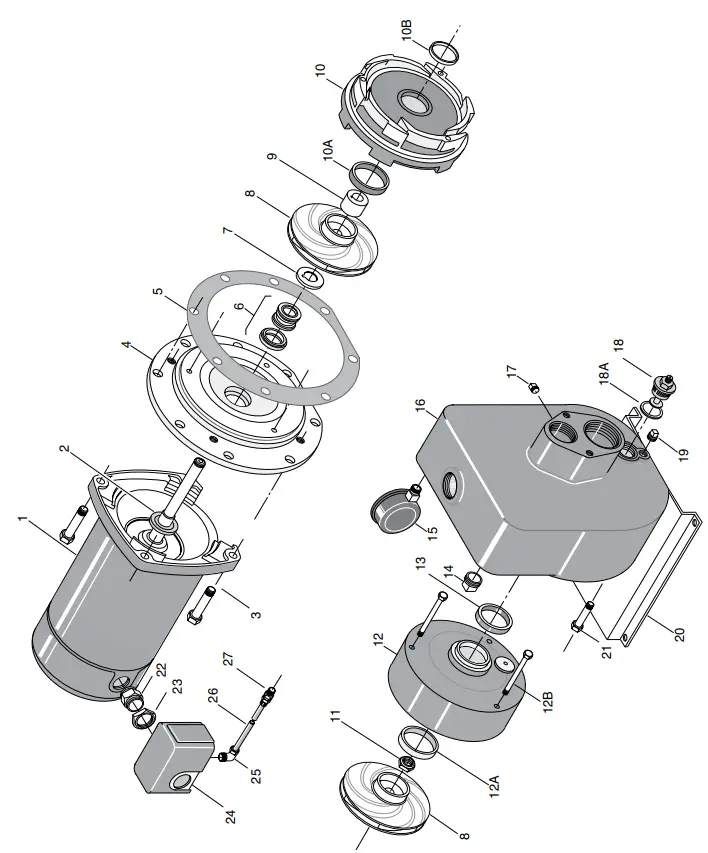
REPAIR PARTS
| KEY NO. | PART DESCRIPTION | W/KIT | NO. USED | HMSD-1FL 3/4 HP | HMSE-1FL 1 HP | HMSF-1FL 1-1/2 HP |
| 1 | Motor, 60 Hz, 115/230V – Single Phase | 1 | A700DH | A700EH | A700FH | |
| •1A | Key – Shaft | OH | 2 | U65-15SS | U65-15SS | U65-15SS |
| 2 | Water Slinger | 1 | 17351-0009 | 17351-0009 | 17351-0009 | |
| 3 | Capscrew – 3/8” x 16 x 1” Hex Head | 4 | U30-74ZP | U30-74ZP | U30-74ZP | |
| 4 | Seal | 1 | L3-26 | L3-26 | L3-26 | |
| 5 | Gasket – Seal Plate | OH/SG | 1 | L20-43 | L20-43 | L20-43 |
| 6 | Shaft Seal | OH/SG | 1 | U109-267 | U109-267 | U109-267 |
| 7 | Spring Holder Washer | OH/SG | 1 | J24-11 | J24-11 | J24-11 |
| 8 | Impeller | OH | 2 | L105-2PC | L105-2PB | L105-2P |
| 9 | Spacer – Impeller | 1 | J43-23 | J43-23 | J43-23 | |
| 10 | Diffuser Assembly w/Wear Rings | 1 | L101-45 | L101-45 | L101-45 | |
| 10A | Wear Ring | OH | (1) | L23-9 | L23-9 | L23-9 |
| 10B | Wear Ring | OH | (1) | P23-19 | P23-19 | P23-19 |
| 11 | Stop Nut – Shaft | OH | 1 | U36-175SSW | U36-175SSW | U36-175SSW |
| 12 | Diffuser Cover w/Wear Ring | 1 | L103-27 | L103-27 | L103-27 | |
| 12A | Wear Ring | (1) | L23-9 | L23-9 | L23-9 | |
| 12B | Capscrew – 1/4” – 20 x 3” Lg. | 3 | U30-528SS | U30-528SS | U30-528SS | |
| 13 | Diffuser Ring | OH/SG | 1 | L21-1 | L21-1 | L21-1 |
| 14 | Pipe Plug – 1/2” NPT | 1 | U78-59ZPS | U78-59ZPS | U78-59ZPS | |
| 15 | Pressure Gauge | 1 | U239-8 | U239-8 | U239-8 | |
| 16 | Pump Body | 1 | L76-36 | L76-36 | L76-36 | |
| 17 | Pipe Plug – 1/8” NPT | 1 | U78-56ZPS | U78-56ZPS | U78-56ZPS | |
| 18 | Valve Assembly | 1 | 01322 | 01322 | 01322 | |
| 18A | Gasket | 1 | L20-39 | L20-39 | L20-39 | |
| 19 | Plug – 1/4” NPT | 1 | U78-941ZPV | U78-941ZPV | U78-941ZPV | |
| 20 | Base | 1 | U4-5 | U4-5 | U4-5 | |
| •20A | Lockwasher – 3/8” | 2 | U43-12ZP | U43-12ZP | U43-12ZP | |
| •20B | Capscrew – 3/8” – 16 x 5/8” Lg. | 2 | U30-71ZP | U30-71ZP | U30-71ZP | |
| 21 | Capscrew – 3/8” – 16 x 7/8” Hex Head | 8 | U30-73ZP | U30-73ZP | U30-73ZP | |
| 22 | Connector | 1 | L43-5C | L43-5C | L43-5C | |
| 23 | Locknut – 1/2” | 1 | U36-112ZP | U36-112ZP | U36-112ZP | |
| 24 | Pressure Switch | 1 | U217-1216 | U217-1216 | U217-1217 | |
| 25 | Compression Fitting – Elbow – 1/4” | 1 | U111-212T | U111-212T | U111-212T | |
| 26 | Tube – Pressure Switch | 1 | U37-677P | U37-677P | U37-677P | |
| 27 | Compression Fitting – Straight – 1/4” | 1 | U111-100T | U111-100T | U111-100T |
• Not shown.
SERVICE KITS
| Seal and Gasket Kit | 1 | PP1625 | PP1625 | PP1625 |
| Overhaul Kit | 1 | PP1631 | PP1632 | PP1633 |
| NOTE: SG Included in Seal and Gasket Kit. OH Included in Overhaul Kit. | ||||
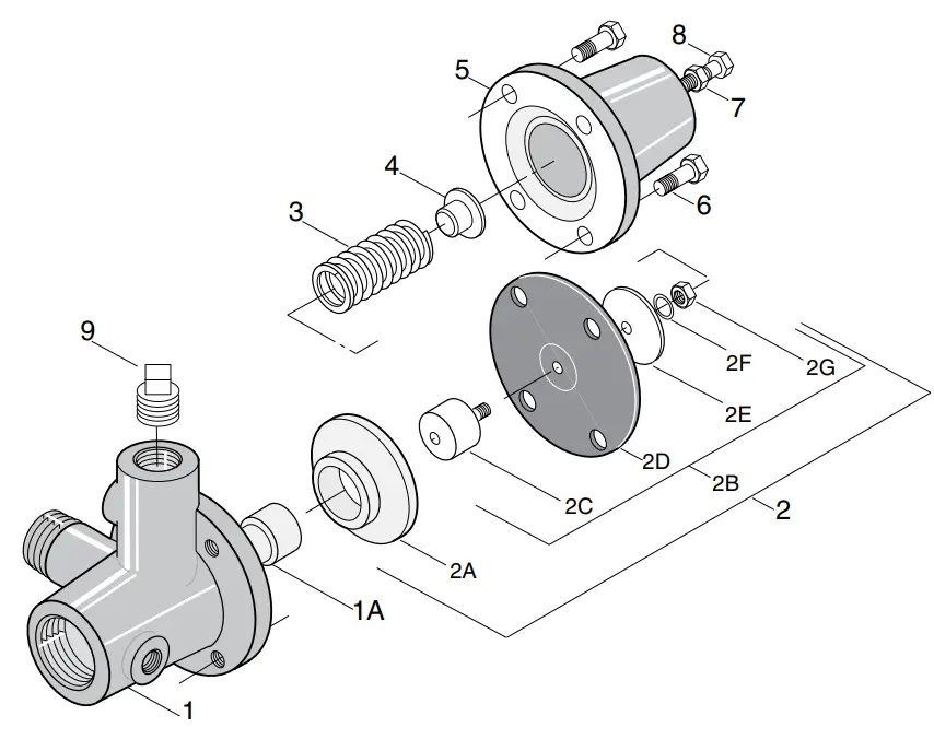
REPAIR PARTS
| KEY NO. | PART DESCRIPTION | QTY. | PART NUMBER |
| Pressure Regulator – Complete | 1 | Pkg. 107 | |
| 1 | Regulator Body w/Seat | 1 | J112-14 |
| 1A | Seat | 1 | J66-16 |
| 2 | Diaphragm Assembly w/Guide (Incl. 2A, 2B) | 1 | J220-16B |
| 2A | Guide | 1 | J42-5 |
| 2B | Diaphragm Assembly (Incl. 2C, 2D, 2E, 2F, 2G) | 1 | J120-16 |
| 2C | Stem | 1 | J62-9 |
| 2D | Diaphragm | 1 | J20-16 |
| 2E | Spring Follower | 1 | J43-31 |
| 2F | Lockwasher | 1 | J43-23ZP |
| 2G | Nut 1/4-20 | 1 | U36-36ZP |
| 3 | Spring | 1 | J24-13 |
| 4 | Spring Guide | 1 | J61-5 |
| 5 | Bonnet | 1 | J52-9 |
| 6 | Capscrew 5/16-18 | 4 | U30-60ZP |
| 7 | Hex Nut 5/16-18 | 1 | U36-37ZP |
| 8 | Adjusting Screw 5/16-18 | 1 | U30-665ZP |
| 9 | Pipe Plug 1/2 NPT | 1 | U78-59ZPS |
| • | Compression Fitting 1/4” 90°EL | 1 | U111-86T |
| • | Tubing – Pressure Switch | 1 | U37-625P |
• Not shown![]()


