UeeVii CPE450 Outdoor CPE
Note
- Thank you for order and using our product, please read the manual carefully before use. If there are any problems during the use, please contact us in time;
- The installation of this device requires some network knowledge. If you can’t install it, please let us know or contact a professional. Tech Service Email: [email protected]
Get Started to Know Your Wireless Bridge
Package Included
- 2 x Outdoor Wireless Bridge
- 2 x PoE Adapter
- 2 x Metal Cable Tie
- 1 X User Manual
- Note: This wireless bridge is powered by a PoE adapter through a network cable, so does not require a DC power supply. The DC power adapter and cable are not included in the package.
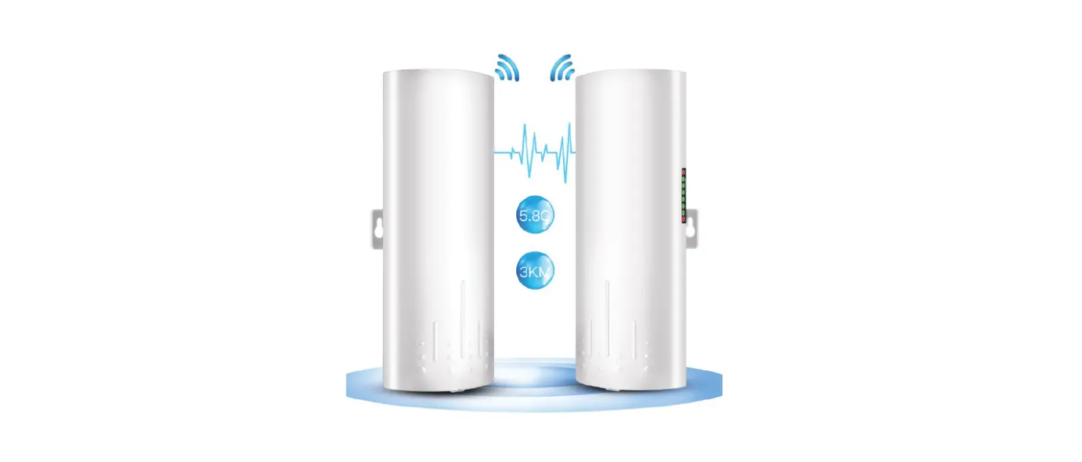
CPE Bridge For Video Transmission Introduction
CPE is widely used in highways, reservoir river monitoring, elevator monitoring systems, site crane monitoring systems, port terminal monitoring systems, marine aquaculture monitoring systems and so on. CPE Video Bridge Transmission usually consists of two devices in AP and Client mode respectively. At the Client-side (Receiving side) CPE connects with IP Camera, at the AP side (Transmitting side) CPE connects with a video recorder. The AP can be receiving wireless data transmitted from multiple Clients, and it is easy and convenient for centralized management of the remote equipment. In addition to helping you in remote monitoring, wireless bridges can also help you extend the network signal to warehouses, barns, garages, and other buildings near your home.
Outdoor CPE Function
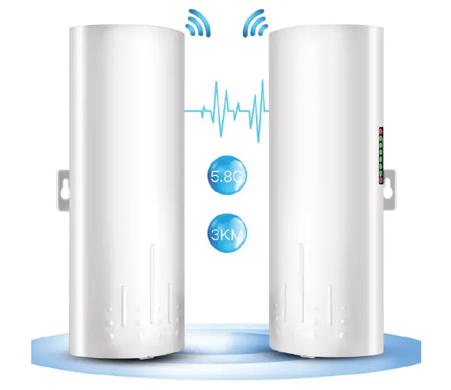
- Long-distance 5.8G wireless transmission equipment
- Support point-to-point, point-to-multipoint mode
- Transmission distance up to 3km(Barrier-Free)
- WDS networking mode, video network dual compatible.
- Dialing to set the transmitter and receiver, and also support the PC to modify the IP settings.
- Dynamic MIMO power-saving mode (DMPS) and automatic power-saving transmission (APSD)
Outdoor CPE Specification
- Model: CPE450
- Master control: AR9344
- DRAM: DDR2 64MByte
- FLASH:8MByte
- Wired Interface:10/100Mbps LAN*2
- CPE Transmission rate: 300Mbps (not network rate)
- Transfer method: Direct Sequence Spread Spectrum (DSSS)
- Modulation: OFDM/BPSK/QPSK/CCK/DQPSK/DBPSK
- Network Standard:IEEE802.11n,IEEE802.11a ,IEEE802.3u
- Supporting agreement: CSMA/CA TCP/IP, IPX/SPX, NetBEUI, DHCP, NDIS3, N-DIS4, NDIS5
- Frequency Range: 4900~6100MHz
- Power consumption: ≤3W
- Power scheme: POE 24V 1A
- Antenna gain: 14DBi
- Management settings: WEP management, Telnet, Serial
- Encryption:WEP encryption 64/128bits, WPA, WPA2, 802.1x
- Operating temperature:-30℃~65℃
Connection Diagram
Transmitting Side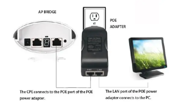
Receiving Side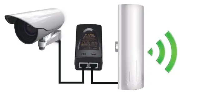
Digital Display Wireless Bridge Set Up
It is strongly recommended to pair the wireless bridge in this way. The digital display bridge is simply connected by dialing. After setting Bridge 1 and Bridge 2 to A and B mode, set the two bridges to the same number(1,2,3,…, F) through the “reset” button, then the two bridges can be automatically connected without using a computer for IP setting. The dialing settings are only connected using a point-to-point bridge, which is not suitable for point-to-multi-point connections.
Connection Diagram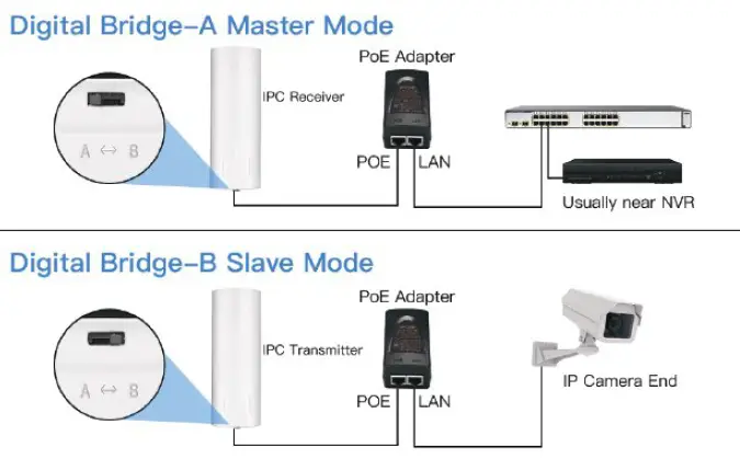
Before connecting the power supply, move bridge 1 to the A end through the A-B button, and bridge 2 moves to the B end through the A-B button, the A end represents the receiving mode, the B end represents the transmitting mode; The bridge 1 and the bridge 2 are respectively set after A and B. Connect the bridge to the power supply, the digital display shows “L” and flashes, and the “L” disappears to indicate that the configuration connection is successful.
The reset button to set the led digital display, click once the startup configuration status is, and continue to click, the number will increase, and can be continuously increased.
Assume that a pair of bridges with a number of 3 is configured After bridge 1 set to 3, after bridge 2 set to 3, first the LED light will flash, then “L” flashes to indicate the application is being configured, please be patient, When “L” flashes, it will become the number “3”, and the number “3” will continue to flash until the bridge 1, bridge 2 is connected after the success, the LED display “3” is always on, not flashing, indicating that the bridge 1 and bridge 2 has been successfully networked.
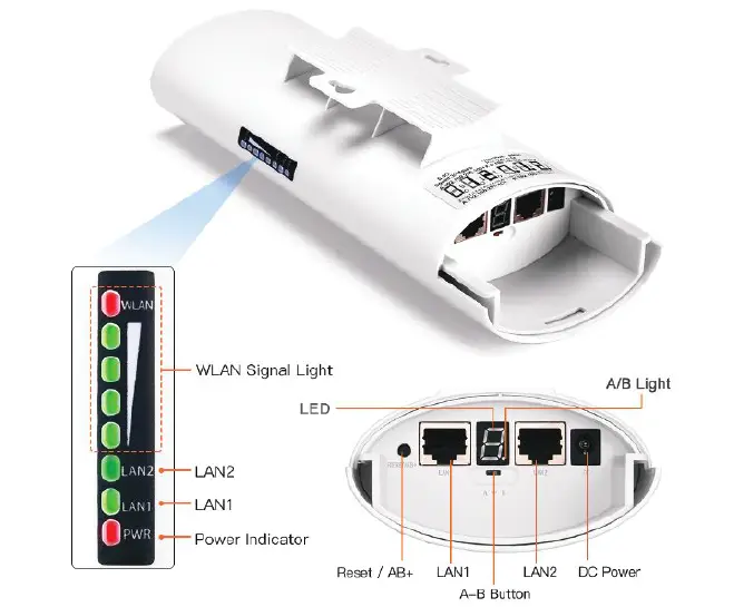
LED Indication Chart
| WLAN | After the bridge is connected successfully, the WLAN light will be on, not connected the WLAN light will not be lit. |
| LAN1/LAN2 | The data connection is successful, the LED light is on, otherwise, it is not bright. |
| PWR | Power indicator, the LED is on after the power is connected |
| LED | Digital display LED display “H” indicates manual configuration status |
| LED | Digital display LED display “L” and flashing indicates settings status |
| LED | Digital display LED flashing indicates edit the config or conne cting |
| Point Light | A, B status lights, lighting is B mode, no lighting is A mode. |
| RST | Click once, the LED display number increases, looping from 0, 1, …, F. |
| RST | Press over 10s, release the “reset” button, the system automatically restarts |
LED Number & IP Chart
| LED | A IP | B IP | 2.4G ID | 5.8G ID |
| 0 | 192.168.255.100 | 192.168.255.200 | 0 | 0 |
| 1 | 192.168.255.101 | 192.168.255.201 | 1 | 165 |
| 2 | 192.168.255.102 | 192.168.255.202 | 2 | 161 |
| 3 | 192.168.255.103 | 192.168.255.203 | 3 | 157 |
| 4 | 192.168.255.104 | 192.168.255.204 | 4 | 153 |
| 5 | 192.168.255.105 | 192.168.255.205 | 5 | 149 |
| 6 | 192.168.255.106 | 192.168.255.206 | 6 | 48 |
| 7 | 192.168.255.107 | 192.168.255.207 | 7 | 44 |
| 8 | 192.168.255.108 | 192.168.255.208 | 8 | 40 |
| 9 | 192.168.255.109 | 192.168.255.209 | 9 | 36 |
| a | 192.168.255.110 | 192.168.255.210 | 10 | 140 |
| b | 192.168.255.111 | 192.168.255.211 | 11 | 132 |
| c | 192.168.255.112 | 192.168.255.212 | 13 | 124 |
| d | 192.168.255.113 | 192.168.255.213 | 96 | 116 |
| e | 192.168.255.114 | 192.168.255.214 | 50 | 108 |
| f | 192.168.255.115 | 192.168.255.215 | 55 | 100 |
How to Access and Setting the CPE Via PC
Step Description
Step 1
Use a PoE adapter to power the wireless bridge through a network cable. Pay attention to the “PoE” and “LAN” ports marked on the PoE adapter,
and power is supplied by POE instead of a DC power interface.
Step 2
Use a network cable to connect the CPE “LAN” port, connect the network cable to other ends to the PoE Adapter “POE” port, use another network cable to connect to the “LAN” port of the PoE adapter, and connect the other end of the network cable to the computer’s “LAN” port.
Step 3
Find the number of the Wireless Bridge CPE digital display tube. For example, the number is 1 and the CEP is the A master bridge, then the IP of this CPE is 192.168.255.101; if the CPE is the B slave bridge, then the IP address of the CPE is 192.168.255.201.(There is a table corresponding to a number and IP in the manual)
Step 4
Very important step: Modify your computer’s IP address, change your computer’s IP address to 192.168.255.xxx(192.168.255.xxx cannot be the same as the IP of the CPE), make your computer’s IP and the bridge’s IP address be on the same network segment so that you can access them. Please refer to the manual to modify the computer IP address step or Google searches how to modify the computer IP address, it is very simple.
Step 5
After you modify your computer’s IP address, you open the computer browser and enter the IP address of the wireless bridge to access it. For exam-
ple, enter 192.168.255.101 to access.
Step 6
Enter the account password “admin/admin” to access, and set it after successful access.
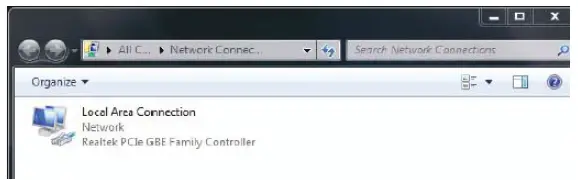
How to Configure Your PC IP As 192.168.255.xxx
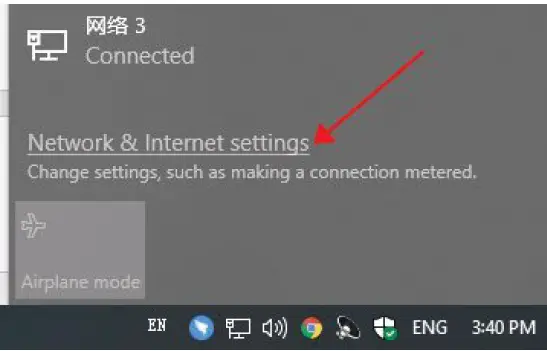
- Find the network icon in the lower right corner and click Open Network and Internet Settings.

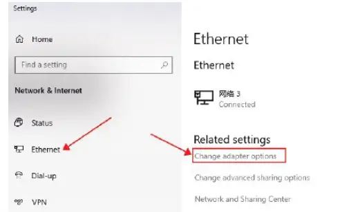
- Select Ethernet and Click the Change Adapter Option.

- Find the network connection you are using and right-click on Properties.

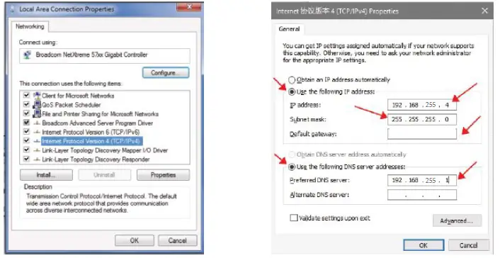
- Double-click the IPV4 setting, select the IP address below, enter the IP and confirm.
- Configure your PC IP as 192.168.255.xxx (xxx is a figure 2-254), note that the set PC IP cannot be the same as the IP of the CPE.

Bridge Configuration (WEB UI)
Note: Before configuring the Bridge IP, AP Configuration, and Client Configuration, make sure that the PC and CPE are properly connected and that the PC IP is configured.
Computer Setup Debug Connection Diagram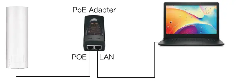
Configure Bridge IP:
Please assign a different IP address to each CPE under the same local area network for easy management.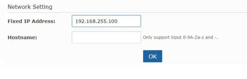
Wireless Receiver Mode(Receiving Point)
Select “A(Master)” under the “Mode”, then select Matching ID(Such as “64(5320Mhz)” ), The matching IDs of A(Master) and B(Slave) must be the same. Create an easy-to-remember name for your wireless network in Host-name.
See the figure below: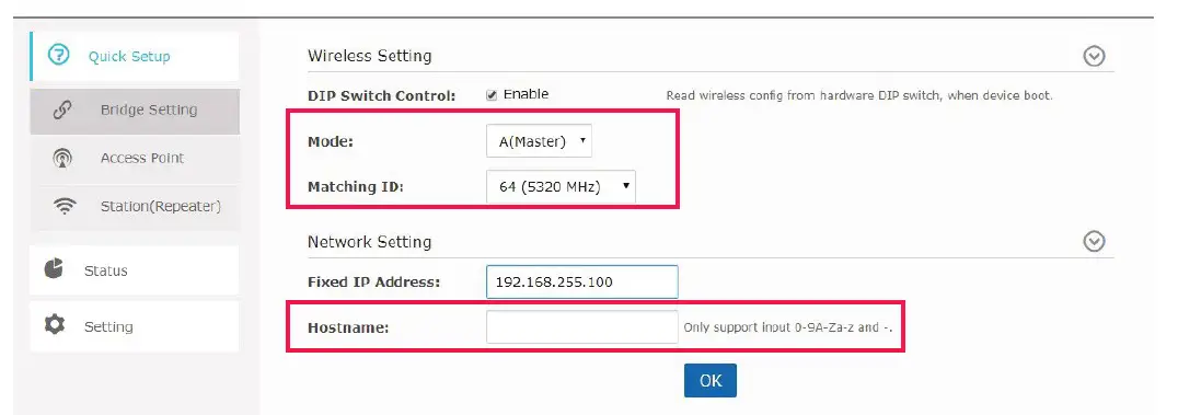
Wireless Transmission Mode(Transmission Point)
Select “B(Slave)” under the “Mode”, then select Matching ID(Such as “64(5320Mhz)” ), The matching IDs of A(Master) and B(Slave) must be the same. Create an easy-to-remember name for your wireless network in Host-name.
See the figure below:
WEB UI Diagram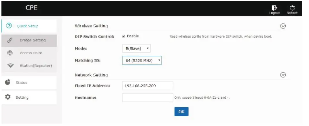
CPE Connection Diagram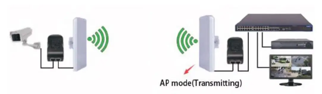
Field Applications
Point-to-Point Connection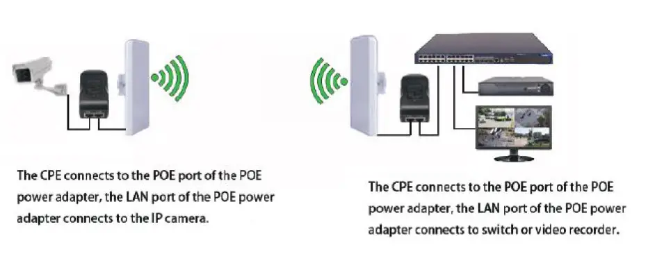
Point o to t Multi-Point Connection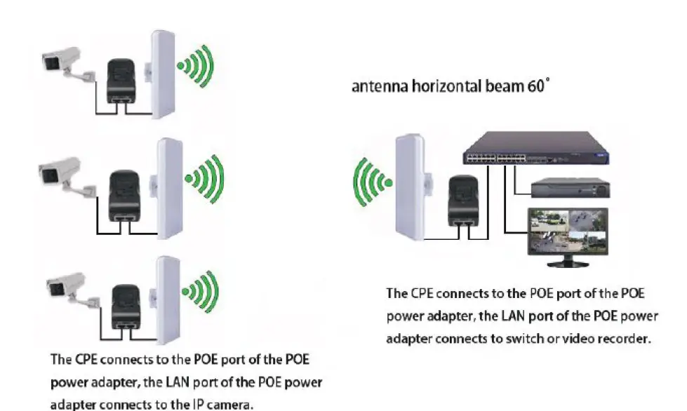
Multiples Clients Connection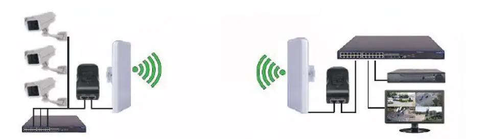
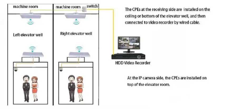
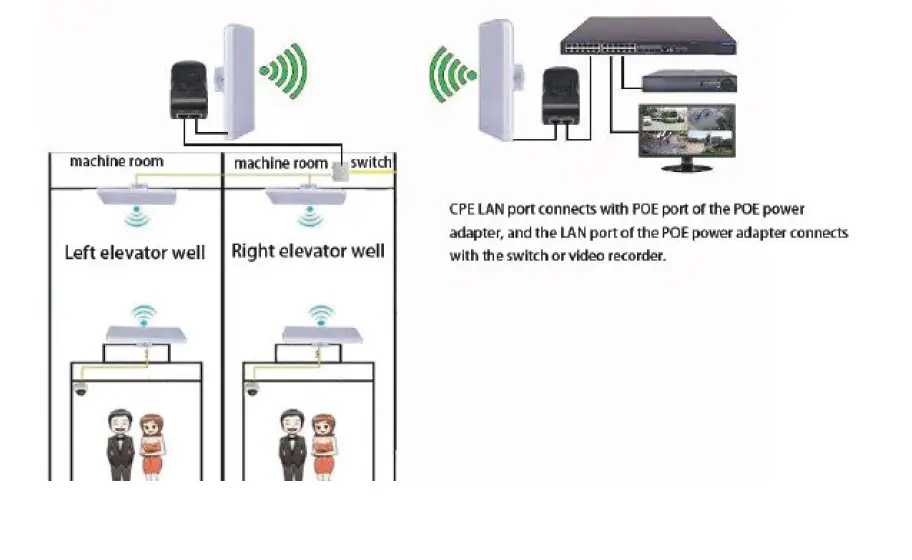
Wireless Surveillance Connection for Elevator Well

Network diagram(3)
Point-to-point Wireless Network Coverage Extend the network to warehouses, barns, and garages near your home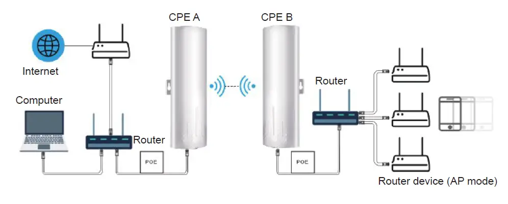
Tips
- The installation of this device requires some network knowledge. If you can’t install it, please let us know or contact a professional. If the product is damaged or missing accessories, please let us know to reissue a new set. This CPE cannot directly expand the WiFi range for you. If you have any questions, you can free feel to let us know via Amazon or Email, we will quickly respond and help you solve your questions.
- The wireless transmission speed between 2 bridges max is 300Mbps. The highest wire network speed that can be achieved max is 100Mbps. Cannot provide up to 300Mbps wired network speed, because the LAN port of the wireless bridge is a 100M port.
FCC WARNING
This device complies with part 15 of the FCC Rules. Operation is subject to the following two conditions: this device may not cause harmful interference, and this device must accept any interference received, including interference that may cause undesired operation. Any changes or modifications not expressly approved by the party responsible for compliance could void the user’s authority to operate the equipment.
NOTE: This equipment has been tested and found to comply with the limits for a Class B digital device, pursuant to Part 15 of the FCC Rules. These limits are designed to provide reasonable protection against harmful interference in a residential installation. This equipment generates, uses and can radiate radio frequency energy and, if not installed and used in accordance with the instructions, may cause harmful interference to radio communications. However, there is no guarantee that interference will not occur in a particular installation. If this equipment does cause harmful interference to radio or television reception, which can be determined by turning the equipment off and on, the user is encouraged to try to correct the interference by one or more of the following measures:
- Reorient or relocate the receiving antenna.
- Increase the separation between the equipment and the receiver.
- Connect the equipment to an outlet on a circuit different from that to which the receiver is connected.
- Consult the dealer or an experienced radio/TV technician for help.
To maintain compliance with FCC’s RF Exposure guidelines, This equipment should be installed and operated with a minimum 20cm distance between the radiator and your body: Use only the supplied antenna.


