 SMAWAVE SRT011 LTE Outdoor CPE
Introduction
This manual will serve as a Quick Start Guide to the LTE Device Model SRM310 with Router. It includes two parts, an indoor unit (IDU) and an outdoor unit (ODU). ODU can provide strong accessibility to the LTE network, and has been designed to meet industrial-grade IP65 dustproof and waterproof standard. Router is a wireless device which can provide ODU power supply via PoE. ODU with Router in combination is the ideal solution for residential LTE network.
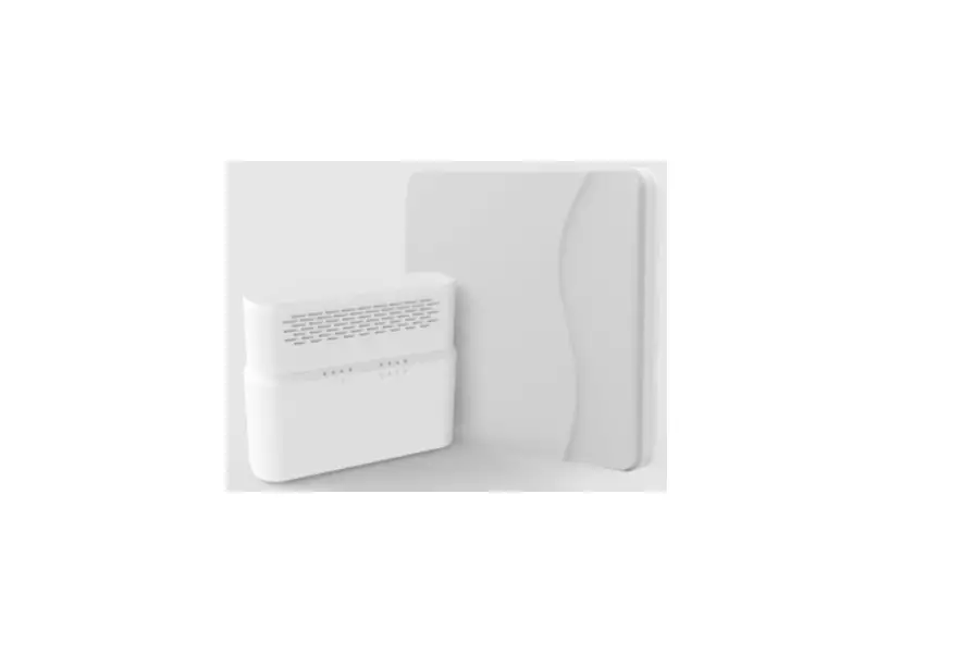
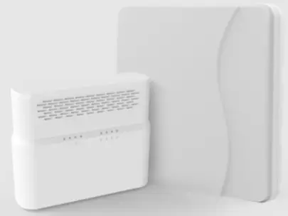
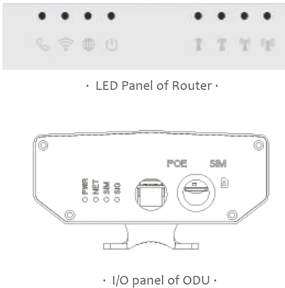
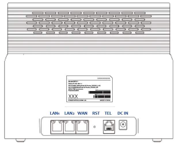
Panel of device
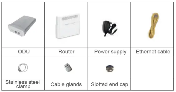
Packing List
Make sure you have everything you need to properly configure the device.
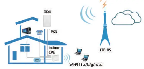
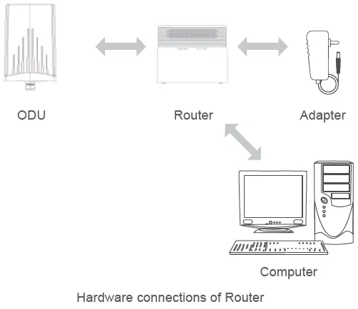
How does it work
- The ODU connects to the LTE network.
- The ODU is connected to the Router, operated with Router to provide Internet sevices.
- The ODU is powered by the Router with PoE.
- The Router functions as a LAN & Wi-Fi gateway.
This quick installation guide shows you how to configure your ODU and Router in order to access the Internet.
Hardware Configuration
CAUTION
Please make sure that you are familiar with all accident prevention and safety procedures necessary for working at height and with electricity before start to intall the device.
DO NOT install the ODU during a lightning storm.
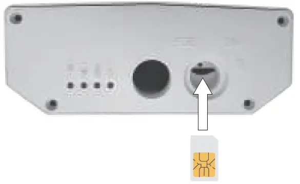
Insert a SIM Card to the Slot
CAUTION
Make sure the ODU is turned off before you insert your SIM card. It is recommended to NOT connect the PoE cable when you do this step. Otherwise, the SIM card may be damaged.
Connect the Router to ODU
Place a CAT5e Ethernet cable from the location of your intended Router to the desired ODU location.
The maximum distance of the CAT5e cable is limited to 50 meters. If you use cable extenders to cover a greater distance, signal attenuation may occur.
If you intend to use cable clamps or other methods to secure the cable, do not tighten them until you finish installing the Router and ODU.
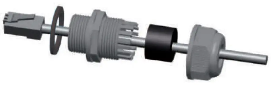
To connect the CAT5e Ethernet cable:
Step 1 CAT5e cable to thread through the cable glands.
Step 2 Connect the end of the CAT5e Ethernet cable to the PoE port of the ODU.
Step 3 Wring the cable glands into ODU and seal tightly.
NOTE: Make sure you have inserted the SIM card into the ODU.
Mount the ODU
See the installation instructions to mount the ODU correctly.
Header Connection
Mounting Bracket
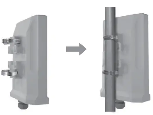
Choose Location
The ODU can be mounted on an antenna pole or mast or on a wall using the supplied mounting bracket.
Choose a mounting point that is sturdy enough to hold the ODU, even during high winds.
When choosing a location to install the ODU, please be noted that the ODU’s front panel should point towards your service provider’s nearest base station. You do not need to be able to see the base station from the ODU’s position. However, if you experience difficulties with signal reception, a Line of Sight (LoS) connection may produce better results.
To obtain the best radio signal level and connection quality, the CPE antenna should be aimed towards the best eNB or BS directly. To search for the best eNB direction, the user can rotate the CPE slowly and tilt CPE slightly to find the best signal direction. The CPE radio signal strength level can be observed from the RF LEDs mounted on the lower panel. Different colored LEDs represent different signal strength.
Connect the Router
Place a CAT5e Ethernet cable from the location of your intended Router to the desired PC location.
If you intend to use cable clamps or other methods to secure the cable, do not tighten them until you finish installing the Router and ODU.
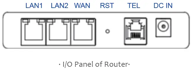
Step 1 Connect the CAT5e Ethernet cable to the Router WAN/PoE port.
CAUTION
Do not connect a computer or switch directly to the PoE port of the Router due to high PoE power.
Step 2 Connect the power adapter to the Router. The POWER LED turns on a solid green-yellow once connected.
Step 3 Connect the included Ethernet cable from the computer to one of the Router’s Ethernet ports.
LED Behavior
When set up the Outdoor Unit, the LED will have the following behavior.
| ODU | ||
| Indicator | Status | Description |
|
POWER | Steady on | Power On |
| Off | No Power Supply | |
|
NET | Steady on | Internet Available |
| Off | Internet Unavailable | |
| Blinking (500ms interval) | Searching Internet | |
|
SIM | Steady on | SIM ready |
| Off | No SIM detected | |
|
SIGNAL | Green | Signal stronge |
| Yellow | Signal good | |
| Red | Signal week | |
| Blinking Green and Red | Firmware upgarde | |
| Router | ||
| Indicator | Status | Description |
|
POWER | Steady on | Power On |
| Off | No Power Supply | |
|
INTERNET | Steady on | Internet Available |
| Off | Internet Unavailable | |
| Blinking (500ms interval) | Searching Internet | |
|
WiFi | Steady on | WiFi Available |
| Off | WiFi unavailable | |
|
TEL | Steady on | Registerd to SIP Server |
| Off | No establishment with SIP Server | |
|
SIGNAL | Steady on | Display the current LTE network signal, the stronger signal, the more bars on |
| Off | No Signal | |
| Blinking one by one | Firmware upgrade | |
Maximum transmit power
Support dual band WiFi 15dBm
Software Configuration
Login to the website
Use a browser to access the management web page to configure and manage the CPE.
The following procedure describes how to use a computer running Windows 7 or above version and Internet Explorer to connect to the CPE webpage.
Step 1 Connect the CPE correctly.
step 2 Start Internet Explorer, go to http://192.168.1.1 in the address bar, and press Enter.
Step 3 Enter the user name and password, and click Log In.
You can connect to the management web page after the password is verified.
Configuration of LTE
Step 1 Connect the CPE correctly.
Step 2 Enter the management website.
Step 3 Choose Settings → Network → LTE Settings.
Step 4 Set the connection mode and scan mode.
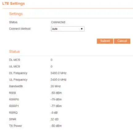
The default setting is automatically connection and full band scanning, if you want to connect the LTE network according to your needs, you can set the connection mode as manual, and simply scan a specified band
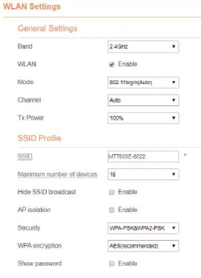
Configuration of Wi-Fi
Step 1 Connect the CPE correctly.
Step 2 Enter the management website.
Step 3 Choose Settings → Wi-Fi → WLAN Settings.
Step 4 In the General Settings area, set WLAN Enable or Disable.
Step 5 In the Setting area, change the SSID, such as:”LTE-Router”
Step 6 To ensure data security, it is recommended that you change the Wi-Fi password by default.
Step 7 Click Submit to save the settings.
Frequently Asked Questions
The POWER indicator does not turn on.
- Make sure that the power cable is connected to the Router, and the CPE is connected to the right port of the Router.
- Make sure that the power adapter and Router are compatible with the
Fails to Log in to the web management page.
- Make sure that the CPE is
- Make sure that the CPE is correctly connected to the computer through a network cable.
If the problem persists, contact authorized local service suppliers.
The CPE fails to search for the LTE network.
- Make sure the power adapter and Router have have connected to the ODU properly.
- Make sure the CPE is placed in an open area that is far away from obstructions, such as concrete or wooden walls.
- Make sure the CPE is placed far away from household electrical appliances that generate strong electromagnetic field, such as microwave ovens, refrigerators, and satellite dishes.
If the problem persists, contact authorized local service suppliers.
The parameters are restored to default values.
- If the CPE powers off unexpectedly while being configured, the parameters may be restored to the default settings.
- After configuring the parameters, download the configuration file to quickly restore the CPE with the desired settings.
Notice
Some features of the product and its accessories described herein rely on the software installed, capacities and settings of local network, and may not be activated or may be limited by local network operators or network service providers, thus the descriptions herein may not exactly match the product or its accessories you purchase.
We reserves the right to change or modify any information or specifications contained in this manual without prior notice or obligation.
FCC Regulations:
- 15.19 (a)(3)
This mobile MIFI complies with part 15 of the FCC Rules. Operation is subject to the following two conditions: (1) This device may not cause harmful interference, and (2) this device must accept any interference received, including interference that may cause undesired operation 15.21
Changes or modifications not expressly approved by the party responsible for compliance could void the user ‘s authority to operate the equipment.
- 15.105 (b)
This mobile phone has been tested and found to comply with the limits for a Class B digital device, pursuant to Part 15 of the FCC Rules. These limits are designed to provide reasonable protection against harmful interference in a residential installation. This equipment generates, uses and can radiated radio frequency energy and, if not installed and used in accordance with the instructions, may cause harmful interference to radio communications. However, there is no guarantee that interference will not occur in a particular installation If this equipment does cause harmful interference to radio or television reception, which can be determined by turning the equipment off and on, the user is encouraged to try to correct the interference by one or more of the following measures:
- Reorient or relocate the receiving antenna.
- Increase the separation between the equipment and receiver.
- Connect the equipment into an outlet on a circuit different from that to which the receiver is connected.
- Consult the dealer or an experienced radio/TV technician for help.
FCC RF Radiation Exposure Statement
This equipment complies with FCC radiation exposure limits set forth for an uncontrolled environment. To comply with FCC RF exposure compliance requirements, this grant is applicable to only Mobile Configurations. The antennas used for the transmitter must be installed to provide a separation distance of at least 20cm from all persons and must not be co-located or operating in conjunction with any other antenna or transmitter.


