![]() EK-Quantum
EK-Quantum
Reflection² PC-O11D XL D5 PWM D-RGB
DISTRIBUTION PLATE
USER GUIDE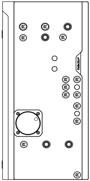
Reflection2 PC-O11D XL D5 PWM D-RGB
Before you start using this product please follow these basic guidelines:
Please carefully read the manual before beginning with the installation process!
The EK Fittings require only a small amount of force to screw them firmly in place since the liquid seal is ensured by the rubber O-ring gaskets.
The use of corrosion inhibiting coolants is always recommended for any liquid cooling system. EKWB recommends any of the EKCryofuel for worry-free usage.
BOX CONTENTS
 EK-Quantum Reflection² PC-O11D XL D5 PWM D-RGB
Mounting Mechanism EAN: 105250
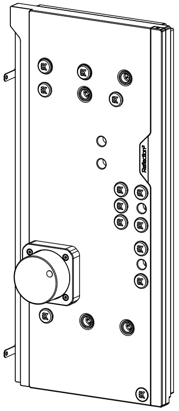
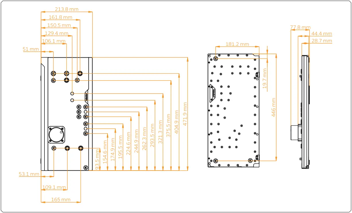
DISTRIBUTION PLATE DIMENSIONS
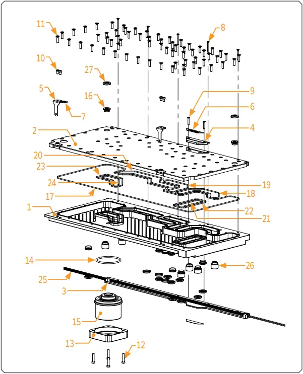
TECHNICAL SPECIFICATIONS AND PRODUCT PARTS
Technical Specification:
Dimensions with the attached pump (W x D x H): 215.1 x 77.8 x 471.9 mm
- D-RGB LED count:
- D-RGB cable length: 500 mm
- D-RGB connector standard 3-pin (+5V, Data, Blocked, Ground)
| Position | EAN | Description | Quantity |
| 1 | 104634 | TOP Plexi -(Block part) | 1 |
| 2 | 104635 | TOP Plexi (Lid part) | 1 |
| 3 | 104639 | LED Cover (Black e.) | 1 |
| 4 | 104642 | Metal plate (Black) | 1 |
| 5 | 104644 | Metal holder (Black) | 2 |
| 6 | 104599 | Mylar sticker | 2 |
| 7 | 100663 | EK – Badge | 2 |
| 8 | 9061 | Screw M3 x 25 DIN7991 | 5 |
| 9 | 9017 | Screw M3 x 18 7991DIN | 2 |
| 10 | 9023 | Screw M4 x 6 DIN7984 | 4 |
| 11 | 8312 | Screw M4 x 16 DIN7991 | 64 |
| 12 | 8311 | Screw M4 x 20 DIN7984 | 4 |
| 13 | 101803 | Pump holder | 1 |
| 14 | 5154 | OR 52 x3 NBR50 | 1 |
| 15 | 3.831E+12 | EK D5 Pump | 1 |
| 16 | 102639 | EK – Plug G1/4 | 14 |
| 17 | 104697 | OR – 438 x 2 mm | 1 |
| 18 | 104698 | OR -105 x 2 mm | 1 |
| 19 | 104699 | OR – 90 x 2 mm | 1 |
| 20 | 104700 | OR -140 x 2 mm | 1 |
| 21 | 104701 | OR -77 x 2 mm | 1 |
| 22 | 104702 | OR -61 x 2 mm | 1 |
| 23 | 104703 | OR – 85 x 2 mm | 1 |
| 24 | 104704 | OR -65 x 2 mm | 1 |
| 25 | 100815 | LED D-RGB strip 800/600 mm | 1 |
| 26 | 3.831E+12 | Push in adapter | 6 |
| 27 | 3.831E+12 | Plug cover (Acetal) | 14 |
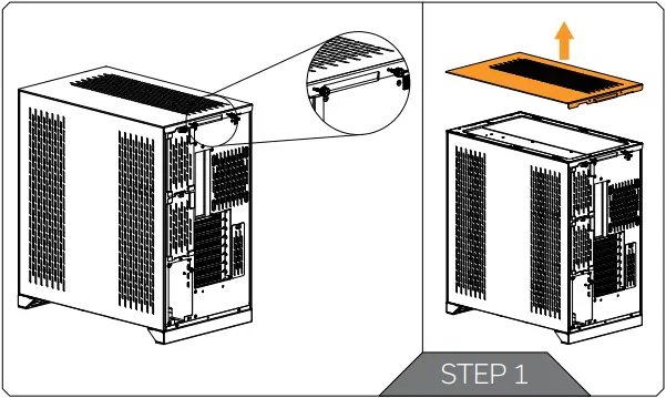
PREPARING THE 011D XL CHASSIS
Before installing the distribution plate, carefully read the PC case manual.
STEP 1
Unscrew the factory provided screws and remove the top panel from the case.
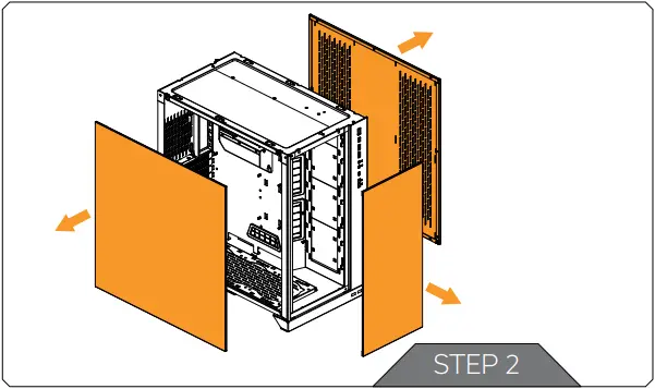
STEP 2
Remove both side panels and the front panel from the case.
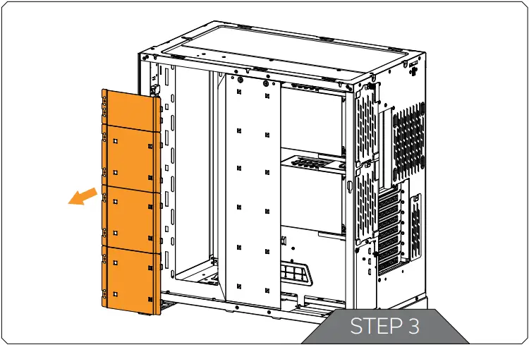
STEP 3
The SSD Trays also need to be removed from the back side of the chassis. Once the distribution plate is secured they can be reinstalled as required.
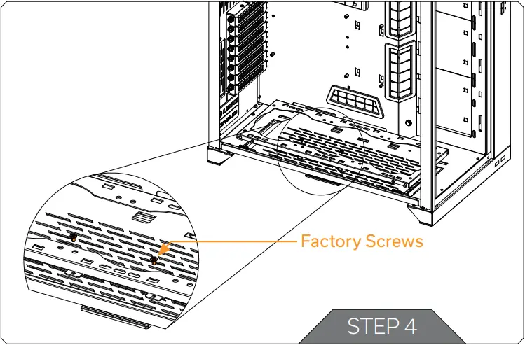
STEP 4
Unscrew the 2(two) marked factory screws and remove the bottom Radiator bracket.
STEP 5
From the original bottom Radiator bracket, remove two (2) marked plastic tabs attached by four (4) cross pattern screws.
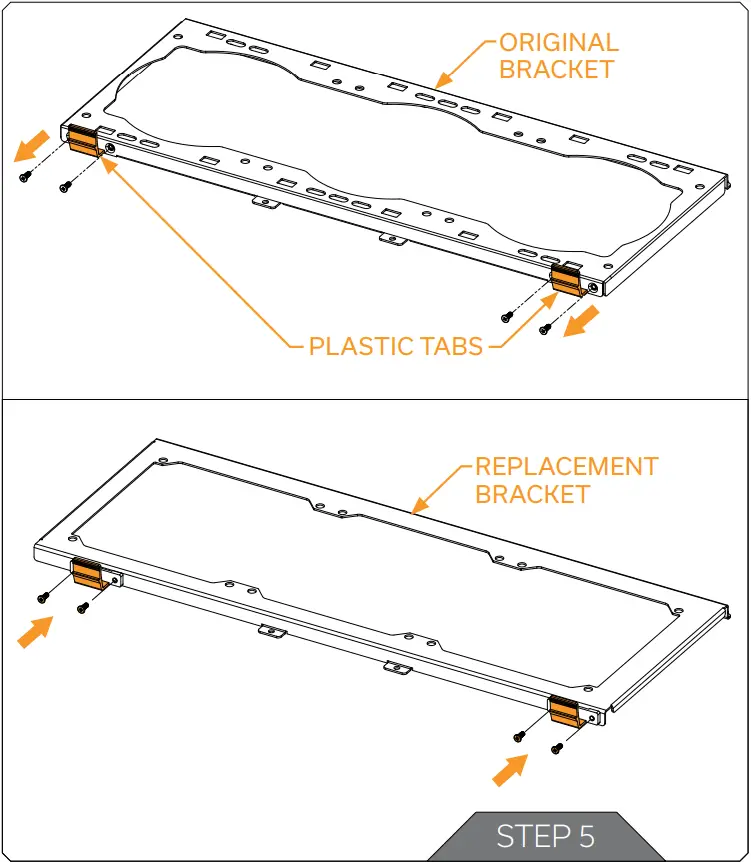
![]() Plastic tabs and screws reattach to the replacement bottom Radiator bracket and secure them with Philips head screwdriver. Tighten the screws evenly.
Plastic tabs and screws reattach to the replacement bottom Radiator bracket and secure them with Philips head screwdriver. Tighten the screws evenly.![]() After securing the distribution plate, replacement bottom Radiator bracket can be installed with the bottom radiator and fans.
After securing the distribution plate, replacement bottom Radiator bracket can be installed with the bottom radiator and fans.
PREPARING AND INSTALLING THE DISTRIBUTION PLATE
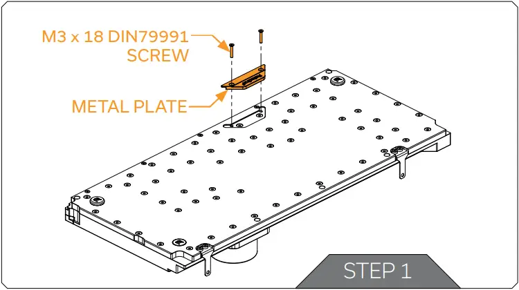
STEP 1
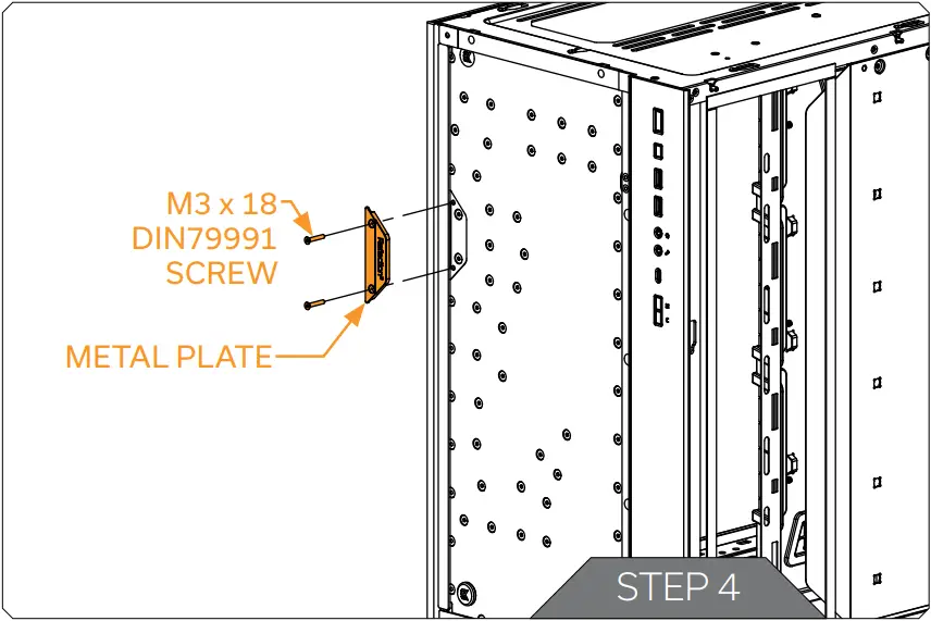
Before installing the distribution plate, unscrew two (2) M3 x 18 DIN7991 Screws and remove the metal plate. Save the removed parts for later steps.
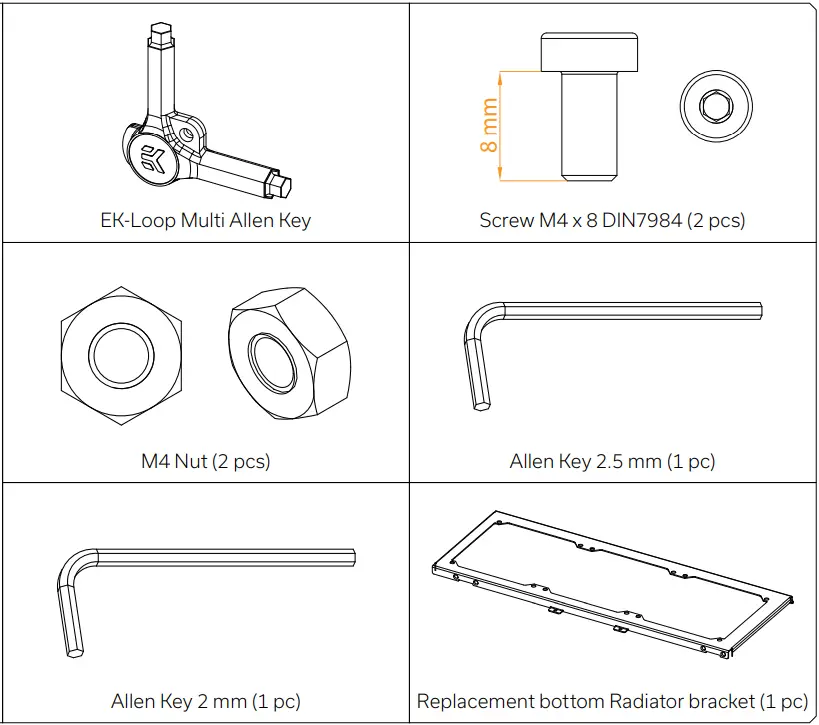
For this step you will need:
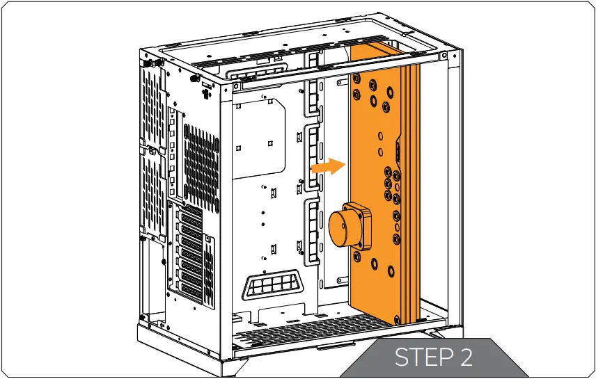
STEP 2
Carefully place the EK-Quantum Reflection PC-O11D XL D5 PWM D-RGB distribution plate into the PC case and align the mounting holes.
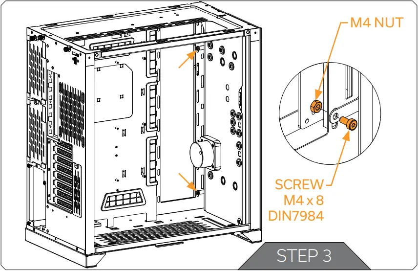
STEP 3
Secure the distribution plate to the chassis with two (2) M4 x 8 DIN7984 and M4 nuts (as shown in the diagram).
STEP 4
After the distribution plate is secured, the stored metal plate can be reattached using two (2) M3 x 18 DIN7991 Screws. Tighten the screws evenly.
For this step you will need:
RECOMMENDED DISTRIBUTION PLATE CONFIGURATIONS
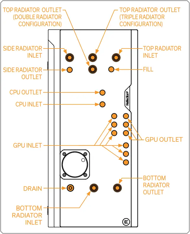
To complete your loop, all ports must be used as marked in the image.
All remaining unused ports must be closed with supplied plugs, using the EK-Loop Multi Allen Key.![]() If one of the prescribed components will not be installed (ie. bottom radiator or GPU block) then one INLET and one OUTLET port must still be joined together in order for this distribution plate to function!
If one of the prescribed components will not be installed (ie. bottom radiator or GPU block) then one INLET and one OUTLET port must still be joined together in order for this distribution plate to function!![]() Only one INLET and one OUTLET port for the GPU connection can be used, while all other INLET and OUTLET GPU ports must be closed with G1/4 plugs (enclosed in the package).
Only one INLET and one OUTLET port for the GPU connection can be used, while all other INLET and OUTLET GPU ports must be closed with G1/4 plugs (enclosed in the package).
ATTACHING THE PUSH-IN ADAPTER (OPTIONAL)
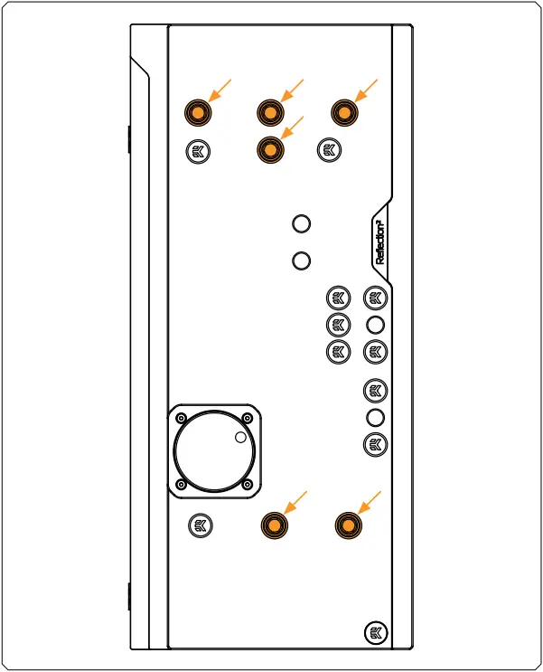
The push-in adapters can be attached to the marked places in the diagram.
For easier installation of the push-in adapters, EK recommends to lubricate the O-rings with a few drops of coolant or water.
CONNECTING THE D-RGB LED STRIP
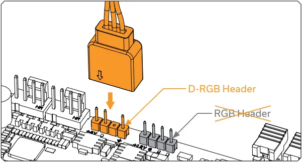
Plug the 3-pin connector of the distribution plate D-RGB LED light to the D-RGB HEADER on the motherboard. The LED will work if the pin layout on the header is as follows: +5V, Digital, Empty, Ground.
CONNECTING THE PUMP
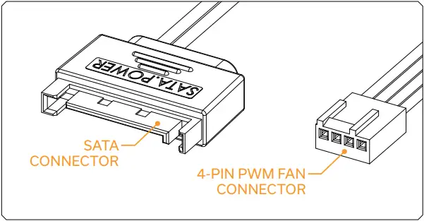
The EK-D5 PWM pump has two connectors.
- SATA Connector: It must be connected directly to your PSU at all times as it is used to power the pump.
- 4-pin PWM fan: It can be connected to your motherboard’s CPU_ Fan or designated water pump header. It can also be connected to a controller. This cable is used to control and report the rotational speed of the pump. If it’s not connected, the pump will run at maximum speed (100% PWM).
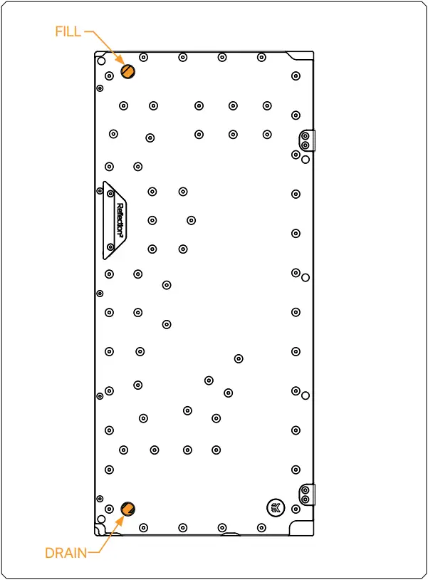
TESTING THE LOOP
To make sure the installation of EK components was successful, we recommend you perform a leak test for 24 hours.
When your loop is complete and filled with coolant, connect the pump to a PSU outside of your system. Do not connect power to any of the other components. Turn on the PSU and let the pump run continuously. It is normal for the coolant level to drop during this process as air collects in the distribution plate.
Inspect all parts of the loop, and in the eventuality that coolant leaks, fix the issue and repeat the testing process. Ensure that all hardware is dry before the system is powered on in order to prevent any damage.
SUPPORT AND SERVICE
In case you need assistance or wish to order spare parts or a new mounting mechanism, please contact: https://www.ekwb.com/customer-support/
For spare parts orders, refer to the page with “TECHNICAL SPECIFICATIONS AND PRODUCT PARTS” where you can find the EAN number of each part you might need.
Include the EAN number with quantity in your request. Mounting Mechanism EAN can be found under “BOX CONTENTS”
Thermal pads are readily available in the EK shop
SOCIAL MEDIA![]() EKWaterBlocks
EKWaterBlocks![]() @EKWaterBlocks
@EKWaterBlocks![]() ekwaterblocks
ekwaterblocks![]() EKWBofficial
EKWBofficial![]() ekwaterblocks
ekwaterblocks
![]()


 Installation Guide")


