![]() Merlin WDP Water Detection Panel
Merlin WDP Water Detection Panel
User Manual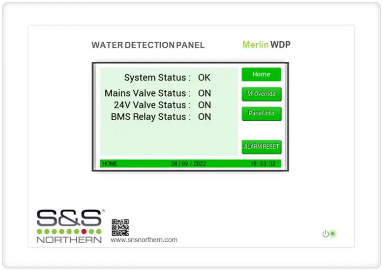
Installation, Operation & Maintenance Instructions
Please read these instructions carefully and retain for future use.
These instructions can be downloaded in electronic form on the product website (www.snsnorthern.com) or a printed version can be ordered free of charge via S&S Northern Limited.
Product Description
The WDP water monitoring system that has been specifically designed to help achieve the requirements of BREEAM 2018 (BRE Environmental Assessment Method). The WDP system is designed to monitor water flowing through a pulse water meter. If the volume of water exceeds the pre-set limit (customer adjustable) the system will alert the customer and, if an optional valve is fitted, can isolate the mains water, therefore limiting the amount of water lost to a leak and subsequent damage.
These instructions can be downloaded in electronic form on the product website (www.snsnorthern.com) or a printed version can be ordered free of charge.![]() Where this symbol is used, the manual must be consulted to understand the nature of any potential hazards and how to avoid them. All safety warnings are listed here for reference.
Where this symbol is used, the manual must be consulted to understand the nature of any potential hazards and how to avoid them. All safety warnings are listed here for reference.![]() Please take the time to thoroughly read these instructions which should be retained for future reference.
Please take the time to thoroughly read these instructions which should be retained for future reference.![]() For specific requirements that may deviate from this manual – contact us.
For specific requirements that may deviate from this manual – contact us.![]() If the equipment is not used in accordance with this manual, the safety of the equipment may be impaired.
If the equipment is not used in accordance with this manual, the safety of the equipment may be impaired.![]() Deviating from the instructions is deemed improper and may affect the functional safety of your device.
Deviating from the instructions is deemed improper and may affect the functional safety of your device.![]() This equipment is intended for dry environment use only.
This equipment is intended for dry environment use only.![]() It is recommended that this equipment be commissioned upon installation.
It is recommended that this equipment be commissioned upon installation.![]() Never ignore the equipment when in alarm or special state.
Never ignore the equipment when in alarm or special state.![]() The equipment requires a continual supply of electrical power – it will not work without power.
The equipment requires a continual supply of electrical power – it will not work without power.![]() Your product should reach you in perfect condition, if you suspect it is damaged, contact your supplier.
Your product should reach you in perfect condition, if you suspect it is damaged, contact your supplier.![]() The equipment and all interconnecting cables must be protected against mechanical damage.
The equipment and all interconnecting cables must be protected against mechanical damage.![]() Avoid conditions of any other environmental factors outside of this specification.
Avoid conditions of any other environmental factors outside of this specification.![]() If mounting direct to wall – ensure the wall surface is flat to prevent base distortion.
If mounting direct to wall – ensure the wall surface is flat to prevent base distortion.![]() Where cable glands/conduits are used for wire entry, use 20mm (3/4 inch) max separated by at least 20mm.
Where cable glands/conduits are used for wire entry, use 20mm (3/4 inch) max separated by at least 20mm.![]() Damage when creating cable entry points or attempting to remove the circuit board may void any warranty.
Damage when creating cable entry points or attempting to remove the circuit board may void any warranty.![]() Restrain the hazardous live wiring from accidental loosening to prevent wires from moving after installation and touching parts of opposite polarity or at low voltages.
Restrain the hazardous live wiring from accidental loosening to prevent wires from moving after installation and touching parts of opposite polarity or at low voltages.![]() Access to the interior, when carrying out any work, must be conducted by a competent person.
Access to the interior, when carrying out any work, must be conducted by a competent person.![]() This instrument has not been designed to be intrinsically safe for use in areas classified as being hazardous locations. For your safety, DO NOT use it in hazardous (classified) locations.
This instrument has not been designed to be intrinsically safe for use in areas classified as being hazardous locations. For your safety, DO NOT use it in hazardous (classified) locations.![]() Except for maintenance detailed in this manual, these products should only be opened and / or serviced by authorized S&S Northern personnel. Failure to comply may void the warranty.
Except for maintenance detailed in this manual, these products should only be opened and / or serviced by authorized S&S Northern personnel. Failure to comply may void the warranty.![]() Assume responsibility for complying with all laws, rules and regulations governing the use of this product.
Assume responsibility for complying with all laws, rules and regulations governing the use of this product.![]() Use only genuine parts and accessories. Failure to comply may impair the product and void the warranty.
Use only genuine parts and accessories. Failure to comply may impair the product and void the warranty.![]() This device is for indoor use only.
This device is for indoor use only.
Information on disposal for consumers of electrical and electronic equipment.![]() When this product has reached the end of its life, treat as Waste Electrical & Electronics Equipment (WEEE). Any WEEE marked products must not be mixed with general household waste, but kept separate for the treatment, recovery and recycling of the materials used.
When this product has reached the end of its life, treat as Waste Electrical & Electronics Equipment (WEEE). Any WEEE marked products must not be mixed with general household waste, but kept separate for the treatment, recovery and recycling of the materials used.
Please contact your supplier or local authority for details of recycling schemes in your area.
Mounting
Designed for surface mounting, it must be installed by a licensed, insured contractor or competent person.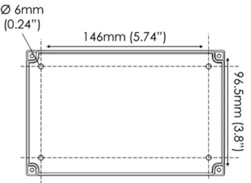 Carefully remove the front cover from the unit by unscrewing the four bolts located at each corner. To do this – use the socket wrench provided. Mark the four screw holes located on the back of the enclosure to the wall ensuring the wall surface is flat to prevent base distortion. Drill out cable entry as necessary ensuring all swarf is removed from the box and holes have smooth edges. After executing the mounting and the connections – replace the front cover and insert the security caps over the four bolts.
Electrical Connections
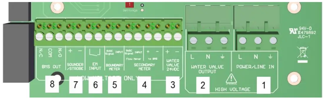
| No | Description | Label | Termination |
| 1 | 100-240V AC Power Input Voltage, 50-60Hz | POWER/LINE IN | L Live N Neutral Earth |
| 2 | 100-240V AC Water Valve Output | WATER VALVE OUTPUT | L Live N Neutral Earth |
| 3 | 24V DC Water Valve Output | WATER VALVE 24VDC | + – |
| 4 | Secondary Flow Meter 5V DC Signal & Input (Two-channel pulse splitter) | SECONDARY METER | 5VDC SIGNAL INPUT + – |
| 5 | Boundary Meter 5VDC Signal & Input | BOUNDARY METER | 5VDC SIGNAL INPUT |
| 6 | Volt Free Open/Close Switch | EM INPUT | L |
| 7 | 24V DC (Alarm Condition) Output for Sounder/Strobe | SOUNDER/STROBE | + – |
| 8 | BMS Relay (Rating: 8A, 250V AC) Normally Closed (Fail Safe) | BMS OUT | NC COM NO |
Inputs & Outputs
- 100-240V AC Power Supply
Internally fused at 3A, the panel requires an isolated power supply unit that is certified by a national or international standard. Upon power up, the LED indicator will illuminate – located on the front lid. - 100-240V AC Water Valve Output.
Relay Output shuts off the water supply when system is in alarm condition.
24V DC Water Valve Output.
Relay Output shuts off the water supply when system is in alarm condition.
Secondary Meter
Connect the pulse output of the water meter. These terminals are not polarity sensitive. The WDP is equipped with a two-channel pulse splitter (labelled ‘to BMS’). This enables the panel to give real time flow volume information to external equipment such as a BMS. If the cable on the meter requires extending the connection should be made using a shielded 2 core cable. Meters connected to the WDP should provide dedicated volt free pulse for volumes of 1/10/100 litre(s).
Minimum cable size should be 1.5mm². For runs adjacent to mains cabling the shield of the pulse cable should be grounded at the controller end only using the Earth terminals to prevent interference. Boundary Meter
Connect the pulse output of the water meter. These terminals are not polarity sensitive. Meters connected to the WDP should provide dedicated volt free pulse for volumes of 1/10/100 litre(s). If the cable on the meter requires extending the connection should be made using a shielded 2 core cable. Minimum cable size should be 1.5mm². For runs adjacent to mains cabling the shield of the pulse cable should be grounded at the controller end only using the Earth terminals to prevent interference.
EM Input
Volt free normally closed input, when open this terminal will trigger an alarm condition.
Sounder/Strobe
24V DC output for an external sounder alarm / strobe lighting etc. when in alarm condition.
BMS Output
These are volt free terminals. This is a relay that changes state in alarm condition and is used in conjunction with the 24V DC output and other external relays that affect other devices and controls such as purge fans and audible alarms etc
System Setup
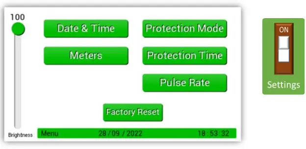 When the settings switch is turned on, the panel screen will display the settings menu. When setup is complete, turning off the switch will save all settings.
Adjusting the Date & Time 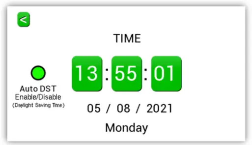 Press the time, date, or Auto DST section to adjust. To return to menu, press the back arrow.
Selecting Meters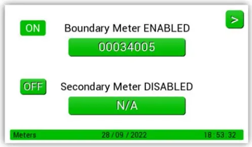 The example shows meter 1 enabled (on) and meter 2 off. If two pulse meters are being used both should be enabled here. To enable, or disable, a meter, press the on/off button on the screen.
The meter values shown on the meter dials should be entered using the edit buttons. This will ensure the meter readings match the panel.
Protection Mode: Volume Per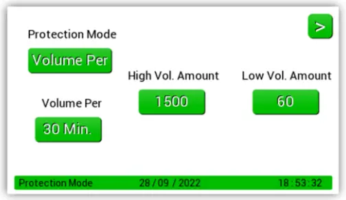 In this mode the system will allow a set amount (volume) of water through the pulse meter during a defined period. By combining these values, you increase/decrease the sensitivity of the systems measurement of flow volume. To edit the flow volume, press the button under the high or low volume value you wish to adjust. Use the arrows to adjust values, press enter to save and return to the screen shown.
In the example shown above the system will allow 1500ltr per half hour during high volume periods, and 60ltr per half hour during low volume periods. Any water use above this level will put the system into alarm.
Protection Mode: Timed 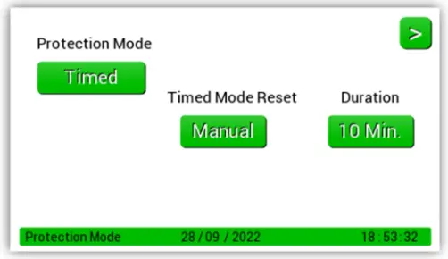 Timed does not measure volume. Instead, it will allow water flow for defined periods of time. (10, 15, 30 or 60 minutes).
Any uninterrupted flow above this user defined time will put the system into alarm. In this example the unit is set for 10 minutes. If the water flows for 11 minutes the system will go into alarm. If the water runs for 9 minutes, stops, then flows for another 9 minutes, etc the system will not alarm.
There are two Timed Mode Reset options:
- Manual Reset – The alarm reset button must be pressed to stop the alarm and reset the controller
- Automatic Reset – The controller will automatically reset as soon as the water flow stops.
Protection Mode: Crosscheck 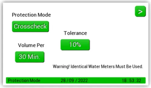 Crosscheck gives the panel flexibility to be used in applications where a comparison of two meters is required, e.g., a block of flats with heat interface units, especially useful if flats are left unoccupied for long periods. The flow and return into each flat can be monitored. If more water goes in than comes out, then the water loss will be noted by the panel resulting in an alarm condition.
There are two adjustments in this section that affect the sensitivity of alarm conditions, tolerance and volume per. Tolerance is measured in percentage and allows a differential (0, 10 or 20%) between channel pulse inputs. Volume per specifies the period of measurement (30mins, 60mins or 24 hours) e.g.,1. Select tolerance 10% and volume per 30mins. This means each 30mins if the pulse input of each channel varies by more than 10% the system will go into an alarm condition. On this setting an expected 100ltr measurement could vary by up to 20ltrs per half hour before an alarm would be given. Total of 480ltrs per 24-hour period.
e.g.,2. Select tolerance 20% and volume per 24hours. This allows up to 20% difference in channel pulse inputs in any 24-hour period. On this setting an expected 100ltr measurement would only allow 40ltrs difference over a 24hr period.
Note: Selecting 0% tolerance requires the pulse inputs to be always matched.
Protection Time![]() For use with Protection Mode: Volume Per
For use with Protection Mode: Volume Per 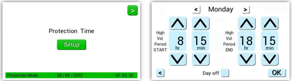
Set the start and end times required for high volume level. Any time outside of the time parameters here are considered low volume levels by the panel and will be measured 0as such, according to the volume levels selected in Protection Mode: Volume per. Tick ‘Day Off’ box to ignore that day.
Different times can be set for each day (each day must be set individually). The general rule for the high-volume times is to set this higher value for when the building is occupied. E.g., For an office you may want to set the high volume (building is occupied) period to start at 8.00 and end at 18.00. In this example in the time between 6pm and 8am the controller will be using the low volume (building is unoccupied) setting.
Pulse Rate 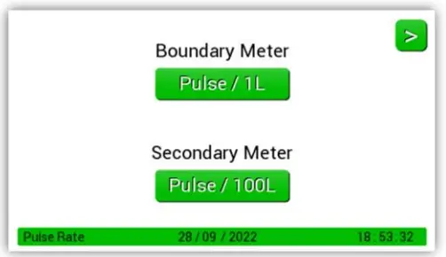 Pulse rates for the water meters connected to the system are selected here. Options available are pulse every: 1, 10, 100 litres.
It is important that the pulse selected should match the output from the meter fitted. If not, the system will not be able to accurately measure water volume. Please contact S&S if you require a suitable pulse meter.
Factory Set Condition
| Setting | Default | Sub Setting | Default |
| Volume Per (Default) | High Vol. Amount Low Vol. Amount Volume Per | 0 Litres 0 Litres 30 Minutes | |
| Protection Mode | Timed | Duration Reset | 10 Minutes Manual |
| Crosscheck | Tolerance Volume Per | 0% 30 Minutes | |
| Pulse Rate | Boundary 1L Secondary 1L | ||
| Protection Time | 7 Days @ 12:00 — 12:00 (Occupied for 24 hours) | ||
| Water Meters | Off | Reading | 0 |
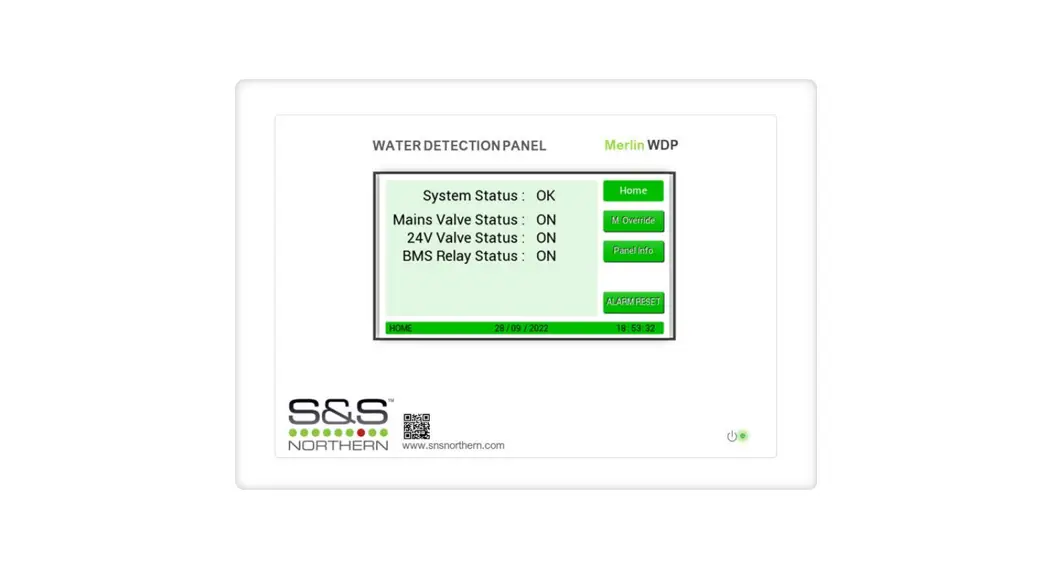
Home Screen
An overview of the panel status, including if connected valves and the BMS relay are ‘on’ or ‘off’. 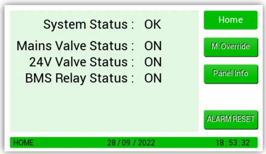 Manual Override
![]() Caution should be taken before enabling the manual override as this means the system will not go into alarm for the selected time-period and your building will not be protected.
Caution should be taken before enabling the manual override as this means the system will not go into alarm for the selected time-period and your building will not be protected.![]() Enabling the manual override will ignore all alarms.
Enabling the manual override will ignore all alarms. 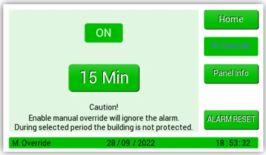 Pressing the ON/OFF button enables the override. There are four pre-set override time periods available. 15, 30, 45 and 60 minutes. Once a time period is selected the “M. Override” button will change to blue and a countdown begins and runs for the selected time period.
Once this has reached zero the button color will return to white, and the system will automatically go back to normal operation. Manual Override can be cancelled at any time by pressing the ON/OFF button.
Panel Information
This screen gives an overview of the system setup only. 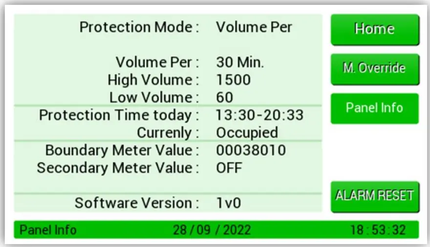 Alarm Reset
If there is an alarm condition, the ALARM RESET button will reset it.
Press Mute to silence the internal audible buzzer. 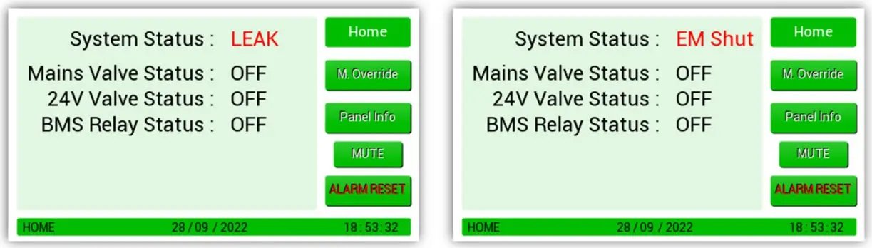
General Maintenance
Keep your panel in good working order – follow these basic principles.
- Remove any dust/debris from the outer enclosure regularly using a slightly damp cloth.
- Never use detergents or solvents to clean your device.
- Never spray air fresheners, hair spray, paint, or other aerosols near/into the device.
- Never paint the device.
Technical Specification
| Construction | User Interface | ||
| Length x Width x Height | 140 x 190 x 62mm | Display | 4.3” Touch Screen |
| Weight | TBC | Language | English |
| Housing Material | ABS UL-94 V1 | Audible Buzzer | >70dB @ 1m |
| Power Supply | Relay Outputs | ||
| Nominal AC Input Voltage | 240V AC | BMS Relay- Volt Free | 8A, 250V AC |
| Frequency | 50-60Hz | Water Valve | 100-240V AC |
| Inrush Current | 700mA | Water Valve | 1A Max 24V DC |
| Internal Fuse | 3.15A 250V AC | Sound/ Strobe | 1A Max 24V DC |
| Maximum Power Consumption | |||
| Normal State | <12W | Alarm Condition | 12W |
| Environmental | |||
| Operating Temperature | -10 ~ 50°C | Overvoltage Category | II |
| Storage Temperature | 0 ~ 40°C | Pollution Degree | 2 |
| Humidity RH | < 90% (non-condensing) | Equipment Class | 2 |
| Altitude Rating | 2000m | Ingress Protection | IP6X |
| Typical Cable Characteristics | |||
| AC Power I/O | 1.5 – 2.5mm2 -Tinned Copper. 1A 100-250V~. Wire Stripping Length 6-7mm | ||
| BMS Relay | 1.5 – 2.5mm2 -Tinned Copper. 10A 100-250V~ Wire Stripping Length 6-7mm | ||
| Other | Other: #1.0-2.5mm2 -Tinned Copper. For field connections use wires suitable for at least 60°C | ||
| Compliance | |||
| Safety | EN 61010-1:2010 +A1:2019; | ||
| EMC | EN 61326-1:2013 | ||
Manufacturer’s Warranty
The manufacturer warrants to the original consumer purchaser, that this product will be free of defects in material and workmanship for a period of one (1) year from date of purchase.
The manufacturer’s liability hereunder is limited to replacement of the product with repaired product at the discretion of the manufacturer. This warranty is void if the product has been damaged by accident, unreasonable use, neglect, tampering or other causes not arising from defects in material or workmanship. This warranty extends to the original consumer purchaser of the product only. Any implied warranties arising out of this sale, including but not limited to the implied warranties of description, merchantability and intended operational purpose, are limited in duration to the above warranty period. In no event shall the manufacturer be liable for loss of use of this product or for any indirect, special, incidental, or consequential damages, or costs, or expenses incurred by the consumer or any other user of this product, whether due to a breach of contract, negligence, strict liability in tort or otherwise. The manufacturer shall have no liability for any personal injury, property damage or any special, incidental, contingent, or consequential damage of any kind resulting from gas leakage, fire, or explosion. This warranty does not affect your statutory rights. During the above warranty period, your product will be replaced with a comparable product if the defective product is returned together with proof of purchase date. The replacement product will be in warranty for the remainder of the original warranty period or for six months – whichever is the greatest.
Installation Details
Please pass this manual to the system owner / user.
Date of Installation:
Installation Location:
Organisation:
Stamp/Signature of the installer:
Every effort is made to ensure the accuracy of this document; however, S&S can assume no responsibility for any errors or omissions in this document or their consequences. S&S would greatly appreciate being informed of any errors that may be found in the content of this document. For information not covered in this document, or if there is a requirement to send comments/corrections, please contact S&S using the contact details.
![]() Find out more
Find out more
S&S Northern Limited
www.snsnorthern.com
S&S Northern Head Office
+44(0) 1257 470 983
[email protected]
Southeast Division
+44(0) 1702 291 725
[email protected]
S&S Northern Limited is the owner of this document and reserves all rights of modification without prior notice.


