
Ingersoll Rand – Nexia Home Intelligence
Nexia One Touch
SKU: NX1000
Quickstart
This is a
Wall Controller
for
U.S. / Canada / Mexico.
To run this device please connect it to your mains power supply.
To add this device to your network execute the following action:
1.Put primary controller into inclusionmode2.Press any button to wake the One Touch3.Press and hold the middle page button (round button) until the Installer Setup menu appears4.Select the ‘Z-Wave’ button5.Select the ‘Include’ button6.Include will fast flash and then SUCCESS will display briefly
Please refer to the
Manufacturers Manual for more information.
Important safety information
Please read this manual carefully. Failure to follow the recommendations in this manual may be dangerous or may violate the law.
The manufacturer, importer, distributor and seller shall not be liable for any loss or damage resulting from failure to comply with the instructions in this manual or any other material.
Use this equipment only for its intended purpose. Follow the disposal instructions.
Do not dispose of electronic equipment or batteries in a fire or near open heat sources.
What is Z-Wave?
Z-Wave is the international wireless protocol for communication in the Smart Home. This
device is suited for use in the region mentioned in the Quickstart section.

Z-Wave ensures a reliable communication by reconfirming every message (two-way
communication) and every mains powered node can act as a repeater for other nodes
(meshed network) in case the receiver is not in direct wireless range of the
transmitter.
This device and every other certified Z-Wave device can be used together with any other
certified Z-Wave device regardless of brand and origin as long as both are suited for the
same frequency range.
If a device supports secure communication it will communicate with other devices
secure as long as this device provides the same or a higher level of security.
Otherwise it will automatically turn into a lower level of security to maintain
backward compatibility.
For more information about Z-Wave technology, devices, white papers etc. please refer
to www.z-wave.info.
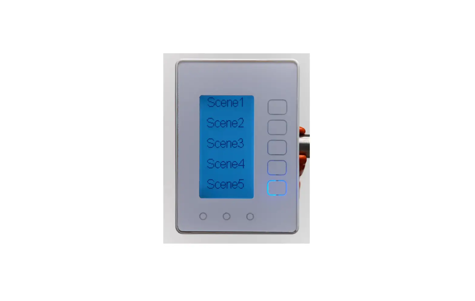
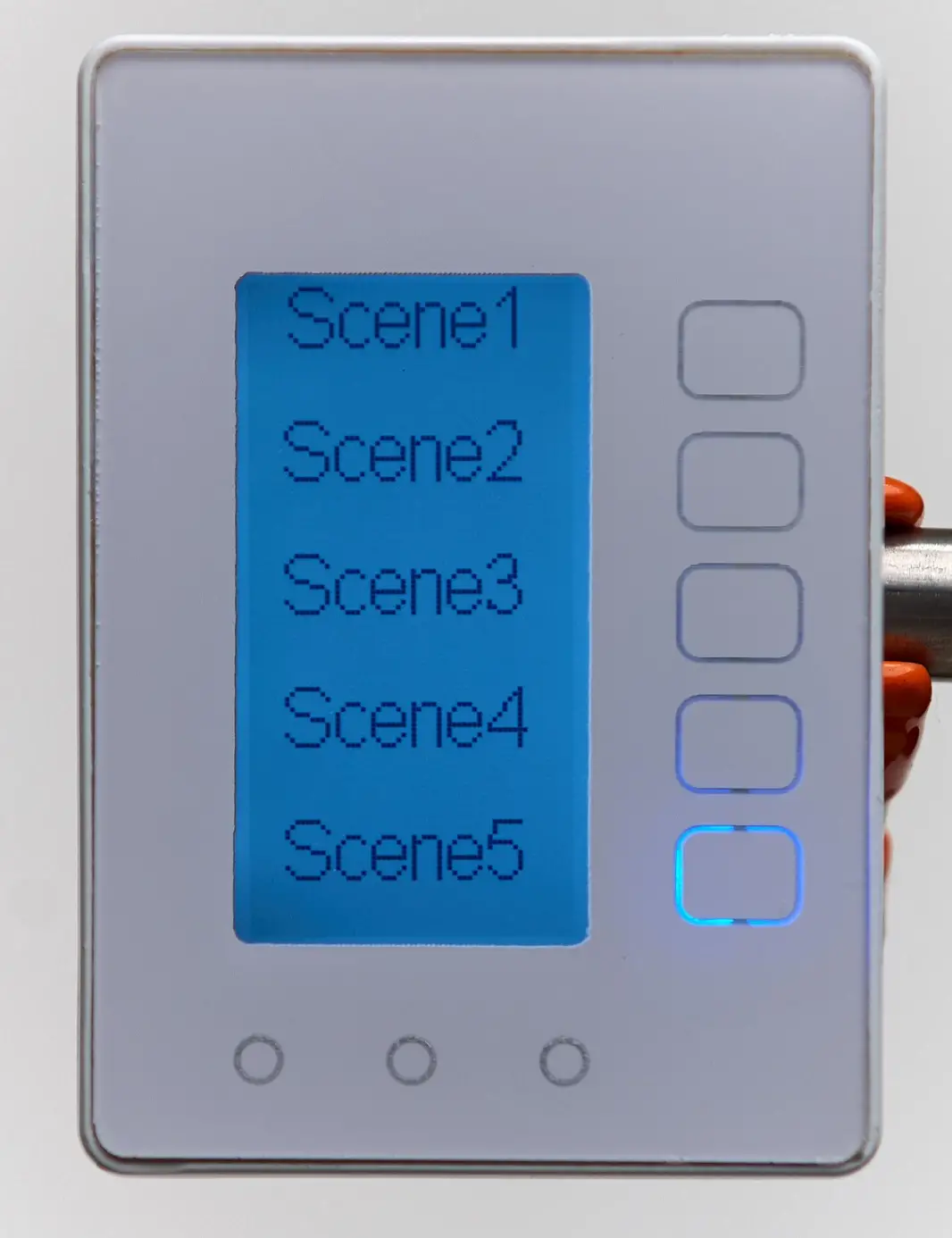
Product Description
The Nexia One Touch is a wall controller device that can act as a central scene controller or a traditional stand-alone scene controller.The Nexia One Touch contains up to 15 different scenes organized in 3 pages of screen where each page contains 5 scenes.The Nexia One Touch conveniently runs up to 15 modes and automations with the tap of a button.
Prepare for Installation / Reset
Please read the user manual before installing the product.
In order to include (add) a Z-Wave device to a network it must be in factory default
state. Please make sure to reset the device into factory default. You can do this by
performing an Exclusion operation as described below in the manual. Every Z-Wave
controller is able to perform this operation however it is recommended to use the primary
controller of the previous network to make sure the very device is excluded properly
from this network.
Reset to factory default
This device also allows to be reset without any involvement of a Z-Wave controller. This
procedure should only be used when the primary controller is inoperable.
Please use Factory Reset as a last resort option only as all network settings and associations will be cleared. 1.Press any button to wake the One Touch2.Press and hold the middle page button (round button) until the Installer Setup menu appears3.Select the ‘System’ button4.Select the ‘Factory Reset’ button5.Select ‘Yes’ to proceed with the factory reset
Safety Warning for Mains Powered Devices
ATTENTION: only authorized technicians under consideration of the country-specific
installation guidelines/norms may do works with mains power. Prior to the assembly of
the product, the voltage network has to be switched off and ensured against re-switching.
Inclusion/Exclusion
On factory default the device does not belong to any Z-Wave network. The device needs
to be added to an existing wireless network to communicate with the devices of this network.
This process is called Inclusion.
Devices can also be removed from a network. This process is called Exclusion.
Both processes are initiated by the primary controller of the Z-Wave network. This
controller is turned into exclusion respective inclusion mode. Inclusion and Exclusion is
then performed doing a special manual action right on the device.
Inclusion
1.Put primary controller into inclusionmode2.Press any button to wake the One Touch3.Press and hold the middle page button (round button) until the Installer Setup menu appears4.Select the ‘Z-Wave’ button5.Select the ‘Include’ button6.Include will fast flash and then SUCCESS will display briefly
Exclusion
1.Put primary controller into exclusion mode2.Press any button to wake the One Touch3.Press and hold the middle page button (round button) until the Installer Setup menu appears4.Select the ‘Z-Wave’ button5.Select the ‘Exclude’ button6.Exclude will fast flash and then SUCCESS will display briefly
Communication to a Sleeping device (Wakeup)
This device is battery operated and turned into deep sleep state most of the time
to save battery life time. Communication with the device is limited. In order to
communicate with the device, a static controller C is needed in the network.
This controller will maintain a mailbox for the battery operated devices and store
commands that can not be received during deep sleep state. Without such a controller,
communication may become impossible and/or the battery life time is significantly
decreased.
This device will wakeup regularly and announce the wakeup
state by sending out a so called Wakeup Notification. The controller can then
empty the mailbox. Therefore, the device needs to be configured with the desired
wakeup interval and the node ID of the controller. If the device was included by
a static controller this controller will usually perform all necessary
configurations. The wakeup interval is a tradeoff between maximal battery
life time and the desired responses of the device. To wakeup the device please perform
the following action:
When the backlight and/or screen is off, the first page (round)button press will wake the One Touch causing it to send a Wakeup Notification report.The One Touch has a 6 hour default wakeup interval and will send the Wakeup Notification once that interval expires. WAKEUP_INTERVAL_CAPABILITIES_REPORTMin Wake Up Interval : 4200 secondsMax Wake Up Interval: 86400 secondsDefault Wake Up Interval: 21600 secondsWake Up Interval Step: 10
Quick trouble shooting
Here are a few hints for network installation if things dont work as expected.
- Make sure a device is in factory reset state before including. In doubt exclude before include.
- If inclusion still fails, check if both devices use the same frequency.
- Remove all dead devices from associations. Otherwise you will see severe delays.
- Never use sleeping battery devices without a central controller.
- Dont poll FLIRS devices.
- Make sure to have enough mains powered device to benefit from the meshing
Association – one device controls an other device
Z-Wave devices control other Z-Wave devices. The relationship between one device
controlling another device is called association. In order to control a different
device, the controlling device needs to maintain a list of devices that will receive
controlling commands. These lists are called association groups and they are always
related to certain events (e.g. button pressed, sensor triggers, …). In case
the event happens all devices stored in the respective association group will
receive the same wireless command wireless command, typically a ‘Basic Set’ Command.
Association Groups:
Group NumberMaximum NodesDescription
| 1 | 2 | Profile: General:LifelineName: Z-Wave Plus LifelineCommand Class List:Battery ReportCentral Scene NotificationDevice Reset Locally Notification |
| 2 | 2 | Profile: Control: Key1Name: Button1 Basic SetCommand Class List:Basic Set |
| 3 | 2 | Profile: Control: Key2Name: Button2 Basic SetCommand Class List:Basic Set |
| 4 | 2 | Profile: Control: Key3Name: Button3 Basic SetCommand Class List:Basic Set |
| 5 | 2 | Profile: Control: Key4Name: Button4 Basic SetCommand Class List:Basic Set |
| 6 | 2 | Profile: Control: Key5Name: Button5 Basic SetCommand Class List:Basic Set |
| 7 | 2 | Profile: Control: Key6Name: Button6 Basic SetCommand Class List:Basic Set |
| 8 | 2 | Profile: Control: Key7Name: Button7 Basic SetCommand Class List:Basic Set |
| 9 | 2 | Profile: Control: Key8Name: Button8 Basic SetCommand Class List:Basic Set |
| 10 | 2 | Profile: Control: Key9Name: Button9 Basic SetCommand Class List:Basic Set |
| 11 | 2 | Profile: Control: Key10Name: Button10 Basic SetCommand Class List:Basic Set |
| 12 | 2 | Profile: Control: Key11Name: Button11 Basic SetCommand Class List:Basic Set |
| 13 | 2 | Profile: Control: Key12Name: Button12 Basic SetCommand Class List:Basic Set |
| 14 | 2 | Profile: Control: Key13Name: Button13 Basic SetCommand Class List:Basic Set |
| 15 | 2 | Profile: Control: Key14Name: Button14 Basic SetCommand Class List:Basic Set |
| 16 | 2 | Profile: Control: Key15Name: Button15 Basic SetCommand Class List:Basic Set |
| 17 | 2 | Profile: Control: Key1Name: Button1Command Class List:Scene Activation Set |
| 18 | 2 | Profile: Control: Key2Name: Button2Command Class List:Scene Activation Set |
| 19 | 2 | Profile: Control: Key3Name: Button3Command Class List:Scene Activation Set |
| 20 | 2 | Profile: Control: Key4Name: Button4Command Class List:Scene Activation Set |
| 21 | 2 | Profile: Control: Key5Name: Button5Command Class List:Scene Activation Set |
| 22 | 2 | Profile: Control: Key6Name: Button6Command Class List:Scene Activation Set |
| 23 | 2 | Profile: Control: Key7Name: Button7Command Class List:Scene Activation Set |
| 24 | 2 | Profile: Control: Key8Name: Button8Command Class List:Scene Activation Set |
| 25 | 2 | Profile: Control: Key9Name: Button9Command Class List:Scene Activation Set |
| 26 | 2 | Profile: Control: Key10Name: Button10Command Class List:Scene Activation Set |
| 27 | 2 | Profile: Control: Key11Name: Button11Command Class List:Scene Activation Set |
| 28 | 2 | Profile: Control: Key12Name: Button12Command Class List:Scene Activation Set |
| 29 | 2 | Profile: Control: Key13Name: Button13Command Class List:Scene Activation Set |
| 30 | 2 | Profile: Control: Key14Name: Button14Command Class List:Scene Activation Set |
| 31 | 2 | Profile: Control: Key15Name: Button15Command Class List:Scene Activation Set |
| 32 | 2 | Profile: Control: Key1Name: Button1Command Class List:Thermostat Setpoint Set |
| 33 | 2 | Profile: Control: Key2Name: Button2Command Class List:Thermostat Setpoint Set |
| 34 | 2 | Profile: Control: Key3Name: Button3Command Class List:Thermostat Setpoint Set |
| 35 | 2 | Profile: Control: Key4Name: Button4Command Class List:Thermostat Setpoint Set |
| 36 | 2 | Profile: Control: Key5Name: Button5Command Class List:Thermostat Setpoint Set |
| 37 | 2 | Profile: Control: Key6Name: Button6Command Class List:Thermostat Setpoint Set |
| 38 | 2 | Profile: Control: Key7Name: Button7Command Class List:Thermostat Setpoint Set |
| 39 | 2 | Profile: Control: Key8Name: Button8Command Class List:Thermostat Setpoint Set |
| 40 | 2 | Profile: Control: Key9Name: Button9Command Class List:Thermostat Setpoint Set |
| 41 | 2 | Profile: Control: Key10Name: Button10Command Class List:Thermostat Setpoint Set |
| 42 | 2 | Profile: Control: Key11Name: Button11Command Class List:Thermostat Setpoint Set |
| 43 | 2 | Profile: Control: Key12Name: Button12Command Class List:Thermostat Setpoint Set |
| 44 | 2 | Profile: Control: Key13Name: Button13Command Class List:Thermostat Setpoint Set |
| 45 | 2 | Profile: Control: Key14Name: Button15Command Class List:Thermostat Setpoint Set |
| 46 | 2 | Profile: Control: Key15Name: Button15Command Class List:Thermostat Setpoint Set |
Configuration Parameters
Z-Wave products are supposed to work out of the box after inclusion, however
certain configuration can adapt the function better to user needs or unlock further
enhanced features.
IMPORTANT: Controllers may only allow configuring
signed values. In order to set values in the range 128 … 255 the value sent in
the application shall be the desired value minus 256. For example: To set a
parameter to 200 it may be needed to set a value of 200 minus 256 = minus 56.
In case of a two byte value the same logic applies: Values greater than 32768 may
needed to be given as negative values too.
Parameter 1: Reserved
Reserved
Size: 1 Byte, Default Value: 0
SettingDescription
| 0 | Reserved |
Configuration for the type of button and which commands it will send when pressed.
Size: 1 Byte, Default Value: 0
SettingDescription
| 0 – 4 | 0x00 = Central Scene0x01 = Scene Control Momentary 0x02 = BASICSET Toggle 0x03 = Scene Control/BASICSET toggle0x04 = Thermostat |
Configuration for the type of button and which commands it will send when pressed.
Size: 1 Byte, Default Value: 0
SettingDescription
| 0 – 4 | 0x00 = Central Scene0x01 = Scene Control Momentary 0x02 = BASICSET Toggle 0x03 = Scene Control/BASICSET toggle0x04 = Thermostat |
Configuration for the type of button and which commands it will send when pressed.
Size: 1 Byte, Default Value: 0
SettingDescription
| 0 – 4 | 0x00 = Central Scene0x01 = Scene Control Momentary 0x02 = BASICSET Toggle 0x03 = Scene Control/BASICSET toggle0x04 = Thermostat |
Configuration for the type of button and which commands it will send when pressed.
Size: 1 Byte, Default Value: 0
SettingDescription
| 0 – 4 | 0x00 = Central Scene0x01 = Scene Control Momentary 0x02 = BASICSET Toggle 0x03 = Scene Control/BASICSET toggle0x04 = Thermostat |
Configuration for the type of button and which commands it will send when pressed.
Size: 1 Byte, Default Value: 0
SettingDescription
| 0 – 4 | 0x00 = Central Scene0x01 = Scene Control Momentary 0x02 = BASICSET Toggle 0x03 = Scene Control/BASICSET toggle0x04 = Thermostat |
Configuration for the type of button and which commands it will send when pressed.
Size: 1 Byte, Default Value: 0
SettingDescription
| 0 – 4 | 0x00 = Central Scene0x01 = Scene Control Momentary 0x02 = BASICSET Toggle 0x03 = Scene Control/BASICSET toggle0x04 = Thermostat |
Configuration for the type of button and which commands it will send when pressed.
Size: 1 Byte, Default Value: 0
SettingDescription
| 0 – 4 | 0x00 = Central Scene0x01 = Scene Control Momentary 0x02 = BASICSET Toggle 0x03 = Scene Control/BASICSET toggle0x04 = Thermostat |
Parameter 17: Reserved
Size: 1 Byte, Default Value: 0
SettingDescription
Parameter 18: Reserved
Size: 1 Byte, Default Value: 0
SettingDescription
Parameter 19: Reserved
Size: 1 Byte, Default Value: 0
SettingDescription
Configuration for the type of button and which commands it will send when pressed.
Size: 1 Byte, Default Value: 0
SettingDescription
| 0 – 4 | 0x00 = Central Scene0x01 = Scene Control Momentary 0x02 = BASICSET Toggle 0x03 = Scene Control/BASICSET toggle0x04 = Thermostat |
Parameter 20: Touch Calibration
Button touch calibration sensitivity level
Size: 1 Byte, Default Value: 10
SettingDescription
| 1 – 10 | 1 = Least Sensitive 10 = Most Sensitive |
Parameter 21: Screen Contrast
Screen contrast level
Size: 1 Byte, Default Value: 7
SettingDescription
| 1 – 10 | 1=less contrast, 10=more contrast |
Parameter 22: Reserved
Size: 1 Byte, Default Value: 0
SettingDescription
| 0 | Reserved |
Button LED Brightness Level
Size: 1 Byte, Default Value: 5
SettingDescription
| 1 – 10 | 1=10% 10 = 100% |
Parameter 24: Backlight Level
Backlight Brightness Level
Size: 1 Byte, Default Value: 5
SettingDescription
| 1 – 10 | 1=10% 10 = 100% |
Backlight timeout after a scene (rectangular) button press
Size: 1 Byte, Default Value: 10
SettingDescription
| 10 – 15 | seconds |
Backlight timeout after a page (round) button press
Size: 1 Byte, Default Value: 5
SettingDescription
| 5 – 15 | seconds |
Parameter 27: Reserved
Size: 1 Byte, Default Value: 0
SettingDescription
Parameter 28: Screen Timeout
Screen timeout- number of minutes after the last button press till the screen goes blank
Size: 1 Byte, Default Value: 60
SettingDescription
| 0 | disabled |
| 1 – 240 | minutes |
Parameter 29: Screen Timeout Primary Page
Page to default to after a screen timeout
Size: 1 Byte, Default Value: 0
SettingDescription
| 0 – 3 | 0 = no change, 1=page1, 2=page2, 3=page3 |
Configuration for the type of button and which commands it will send when pressed.
Size: 1 Byte, Default Value: 0
SettingDescription
| 0 – 4 | 0x00 = Central Scene0x01 = Scene Control Momentary 0x02 = BASICSET Toggle 0x03 = Scene Control/BASICSET toggle0x04 = Thermostat |
Parameter 30: Battery Stat Shutdown Threshold
Battery status shutdown threshold
Size: 1 Byte, Default Value: 5
SettingDescription
| 0 – 20 | % |
Parameter 31: Battery Radio Cutoff Threshold
Battery % Radio Cutoff Threshold
Size: 1 Byte, Default Value: 10
SettingDescription
| 0 – 40 | % |
Parameter 32: Battery LOWBATT Indicator Threshold
Low Battery % Indicator Threshold
Size: 1 Byte, Default Value: 20
SettingDescription
| 5 – 50 | % |
Parameter 33: Battery Threshold Value for Midlevel
Battery % threshold for midlevel indicator
Size: 1 Byte, Default Value: 50
SettingDescription
| 30 – 80 | % |
Configuration for the type of button and which commands it will send when pressed.
Size: 1 Byte, Default Value: 0
SettingDescription
| 0 – 4 | 0x00 = Central Scene0x01 = Scene Control Momentary 0x02 = BASICSET Toggle 0x03 = Scene Control/BASICSET toggle0x04 = Thermostat |
Configuration for the type of button and which commands it will send when pressed.
Size: 1 Byte, Default Value: 0
SettingDescription
| 0 – 4 | 0x00 = Central Scene0x01 = Scene Control Momentary 0x02 = BASICSET Toggle 0x03 = Scene Control/BASICSET toggle0x04 = Thermostat |
Configuration for the type of button and which commands it will send when pressed.
Size: 1 Byte, Default Value: 0
SettingDescription
| 0 – 4 | 0x00 = Central Scene0x01 = Scene Control Momentary 0x02 = BASICSET Toggle 0x03 = Scene Control/BASICSET toggle0x04 = Thermostat |
Configuration for the type of button and which commands it will send when pressed.
Size: 1 Byte, Default Value: 0
SettingDescription
| 0 – 4 | 0x00 = Central Scene0x01 = Scene Control Momentary 0x02 = BASICSET Toggle 0x03 = Scene Control/BASICSET toggle0x04 = Thermostat |
Configuration for the type of button and which commands it will send when pressed.
Size: 1 Byte, Default Value: 0
SettingDescription
| 0 – 4 | 0x00 = Central Scene0x01 = Scene Control Momentary 0x02 = BASICSET Toggle 0x03 = Scene Control/BASICSET toggle0x04 = Thermostat |
Technical Data
| Hardware Platform | ZM5202 |
| Device Type | Wall Controller |
| Network Operation | Portable Slave |
| Firmware Version | 01 |
| Z-Wave Version | 6.51.06 |
| Certification ID | ZC10-15070012 |
| Z-Wave Product Id | 0x0178.0x5343.0x4735 |
| Frequency | XXfrequency |
| Maximum transmission power | XXantenna |
Controlled Command Classes
- Basic
- Central Scene
- Scene Activation
- Thermostat Setpoint
Explanation of Z-Wave specific terms
- Controller — is a Z-Wave device with capabilities to manage the network.
Controllers are typically Gateways,Remote Controls or battery operated wall controllers. - Slave — is a Z-Wave device without capabilities to manage the network.
Slaves can be sensors, actuators and even remote controls. - Primary Controller — is the central organizer of the network. It must be
a controller. There can be only one primary controller in a Z-Wave network. - Inclusion — is the process of adding new Z-Wave devices into a network.
- Exclusion — is the process of removing Z-Wave devices from the network.
- Association — is a control relationship between a controlling device and
a controlled device. - Wakeup Notification — is a special wireless message issued by a Z-Wave
device to announces that is able to communicate. - Node Information Frame — is a special wireless message issued by a
Z-Wave device to announce its capabilities and functions.


