
UNIVERSAL MODULE WITH 3 In 3 Out
The Universal Module is used to translate wired products into wireless Z-Wave protocol, integrating them into the Z-Wave network of a smarthome environment. It has 3 sets of input terminals and 3 sets of relay output. Through the Universal Module, the Z-Wave Controller can read the input signal from wired sensors and control the output of wired actuators. This product can be operated in any Z-Wave network with other Z-Wave certified devices from other manufactures. All mains operated nodes within the network will act as repeater regardless of vender to increase reliability of the network.
Main features:
- 3 sets of input terminals, supporting dry contact or analog input
- Threshold level can be set for each input
- Notifies controller when input triggers
- 3 sets of relay output terminals, delivering NC/NO dry contact output*
- Output can be set to activate automatically when input terminals trigger
- Backup battery during power loss
- Notifies controller if power loss/recovers and when backup battery becomes low
- Tamper switch to detect removal from its mount
- Supports Z-Wave S2 security protocol with security-enabled Controller
*Note: Do not connect the output to high voltage AC mains (100V AC/220V AC).
The SmartStart enabled products can be added into a Z-Wave network by scanning the Z-Wave QR code present on the product with a controller provide SmartStart include. No further action is required and the SmartStart product will be added automatically within 10 minutes of being switched on in the network vicinity. But users should use Auto or Manual Inclusion if their controller does not support SmartStart.
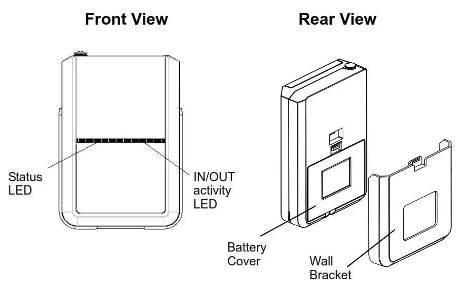
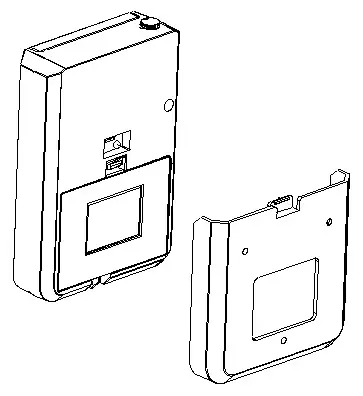
Product Overview
View with Battery Cover removed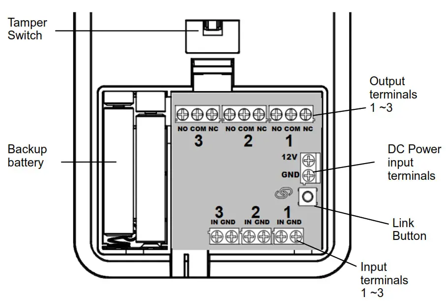
Adding to Z-Wave Network
Auto Inclusion
The Universal Module supports Auto Inclusion feature where it will automatically enter Inclusion mode when first powered up after a factory reset.
- Remove its battery cover
- Set the Z-Wave controller into Inclusion mode.
- Insert the battery into the battery compartment. Note the correct polarity of battery as indicated.
- The Status LED will start to blink. The duration of Inclusion mode is 30 seconds.
- The Inclusion process should be completed when the LED stops blinking.
Note: If you are connecting this unit to a Z-Wave Controller that utilizes the S2 security protocol, you may be asked by your controller to enter a 5-digit PIN that is unique to each unit. This can be found in one of two places:
- on the QR code label on the back of the unit
- on the insert card inside the packaging.
If Auto Inclusion fails, refer to the Troubleshooting section regarding Manual Inclusion.
Connecting wired devices
1. Connect the terminals to external devices according to input or output channels
Input channels
Channels IN1, IN2, IN3, each with its GND terminals.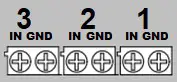
Input type specification :
- Analog : 0~12V
- Digital : 0~12V
- Dry contact output, NC (Normally Close) and NO (Normally Open) type
- Open collector transistor
Features:
- Selectable voltage level trigger threshold (see Configuration settings)
- Internal pull high voltage 3.3V enable/disable
- Input over voltage protection (works even if input voltage is over supply voltage)
- periodic report of voltage level to gateway
- Configure for alarm panels (see Parameter 18 in Configuration settings)
Output channels
Channel OUT1, OUT2, OUT3 each with NO-COM-NC terminals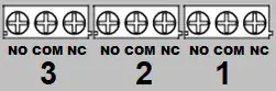 Output specification:
– SPDT type relay
– Relay current limit as follows (at 24V DC)
| Relay | NO terminal | NC terminal |
| OUT1 | 10A | 5A |
| OUT2 | 3A | 3A |
| OUT3 | 3A | 3A |
Note: not suitable for AC mains high voltage applications such as 100VAC/220VAC.
Features:
- Configurable timer to automatically turn off after preset period (default is 500msec)
- Output can be set to activate automatically when input terminals trigger (see Configurationsetting No. 1, 6, 11)
2. Power: Connect an external DC power source, 9V~12V range. Typical 12V / 1A min.
Operation
LED display
Table below describe the LED indication:
Status LED:
| LED display | Indicates |
| ON, Red | External DC power connected |
| Slow blink, Red, every 3 secs | External DC power disconnected, running on backup battery |
| Slow blink, Green, every 2 secs | Factory reset state |
| Fast blink, Green, every 1 secs | Z-Wave Inclusion/Exclusion |
3. IN/OUT Activity LED:
| LED display | Indicates |
| Blink green, twice | Input signal detected |
| Blinks red, twice | Relay output activated |
Tamper Protection:
Pressing the tamper switch over 6 secs activates the tamper detection mechanism. Once activated, releasing the switch will send a notification to the Controller, and if configured, will activate relay on OUT1~ 3. (see Configuration setting No. 17)
Mounting the Unit
The Universal Module can be used only in an indoor environment
- After wiring the terminal blocks, route the wires neatly through the slot at the bottom of the unit.
- If necessary, fit 4 AAA size 1.5 alkaline batteries to the battery compartment.
- Place the rear cover to the battery compartment.
- To mount the unit to the wall, first use the wall bracket supplied as a template to mark and drill the position of two mounting holes on the wall.
- Secure the bracket to the wall using the plastic wall plugs and fixing screws provided.
- Slide the unit down to its bracket to secure into place.
This will also activate the Tamper protection.
Programming
Z-Wave specification
- Z-Wave protocol: SDK 6.81.06
- Support SmartStart; activated when powered on.
- Supports firmware update by OTA.
Endpoint description
| Root | Endpoint 1-3 | Endpoint 4-6 | |
| Role Type | Always On Slave | ||
| Device Type | Notification Sensor | Notification Sensor | Binary Switch |
| Generic Type | Sensor Notification | Sensor Notification | Binary Switch |
| Specific Type | Notification Sensor | Notification Sensor | Not Used |
| Requested security keys | SO • S2 Un-Authenticated • S2-Authenticated | ||
| Endpoint | Basic Command | Mapped |
| 1-3 | Basic Command | no |
| 4-6 | Basic Set (value) | Binary Switch Set (Value) |
| 4-6 | Basic Report(Value) | Binary Switch Report (Value) |
Z-Wave Plus Info
| Endpoint | Role Type | Node Type | Installer Icon | User icon |
| Root | Slave Always On | Z-Wave Plus node | Notification type Home Security | Notification type Home Security |
| 1-3 | Slave Always On | Z-Wave Plus node | Notification type Home Security | Notification type Home Security |
| 4-6 | Slave Always On | Z-Wave Plus node | On/Off Power Switch Device Type | On/Off Power Switch Device Type |
AGI (Association Group Information)
| Group | Name | Max Node | Supports the following command classes |
| 1 | Lifeline | 5 | 1. Device Reset Locally 2. Notification Report 3. Switch Binary Report 4. Sensor Multilevel Report 5. Battery Report |
| 2 | Alarm IN1 | 5 | Mirror of endpoint 1, group 2 |
| 3 | Alarm IN2 | 5 | Mirror of endpoint 2, group 2 |
| 4 | Alarm IN3 | 5 | Mirror of endpoint 3, group 2 |
Association Command Class
– Multi Channel Association Command Class
| Group | Name | Max Node | Supports the following command classes |
| 1 | Lifeline | 5 | 1. Device Reset Locally 2. Notification Report 3. Switch Binary Report 4. Sensor Multilevel Report 5. Battery Report |
| 2 | Alarm IN 1 | 5 | Mirror of endpoint 1, group 2 |
| 3 | Alarm IN2 | 5 | Mirror of endpoint 2, group 2 |
| 4 | Alarm IN3 | 5 | Mirror of endpoint 3, group 2 |
| Endpoint 1 | |||
| 1 | Lifeline | 0 | Mirror of root device |
| 2 | Alarm IN 1 | 5 | Basic Set |
| Endpoint 2 | |||
| 1 | Lifeline | 0 | Mirror of root device |
| 2 | Alarm IN2 | 5 | Basic Set |
| Endpoint 3 | |||
| 1 | Lifeline | 0 | Mirror of root device |
| 2 | Alarm IN3 | 5 | Basic Set |
For Association Groups 2, 3 and 4 :
When signal input is detected in ports IN1~3, SA301 will first send a BASIC Set ON. When the
preset timer is up, it will send a BASIC Set OFF.
Multi Channel : Root map (Association Group Information)
| Sensor Multilevel Command Class | Endpoint 1 |
| Switch Binary Command Class | Endpoint 4 |
| Basic Command Class | Endpoint 4 |
Version
| Protocol Library | Slave Enhance 232 Library |
| Protocol Version | SDK 6.81.06 or later |
| Firmware 0 Version | xVy (x=1,y=0 means WO) |
| Hardware Version | 1 |
Manufacturer data
| Manufacturer ID | Product Type | Product ID |
| 0x0060 | 0x0016 | Ox0001 |
Command Classes
The module supports Command Classes including…
Non-SecureNode Info
- COMMAND_CLASS_ZWAVEPLUS_INFO_V2
- COMMAND_CLASS_ASSOCIATION_V2
- COMMAND_CLASS_MULTI_CHANNEL_ASSOCIATION_V3
- COMMAND_CLASS_ASSOCIATION_GRP_INFO_V1
- COMMAND_CLASS_MULTI_CHANNEL_V4
- COMMAND_CLASS_TRANSPORT_SERVICE_V2
- COMMAND_CLASS_VERSION_V3
- COMMAND_CLASS_MANUFACTURER_SPECIFIC_V2
- COMMAND_CLASS_DEVICE_RESET_LOCALLY_V1
- COMMAND_CLASS_POWERLEVEL_V1
- COMMAND_CLASS_SECURITY
- COMMAND_CLASS_SECURITY_2
- COMMAND_CLASS_SUPERVISION
- COMMAND_CLASS_FIRMWARE_UPDATE_MD_V4
- COMMAND_CLASS_NOTIFICATION_V8
- COMMAND_CLASS_SENSOR_MULTILEVEL_V5
- COMMAND_CLASS_SWITCH_BINARY
- COMMAND_CLASS_CONFIGURATION_V4
- COMMAND_CLASS_BATTERY
Endpoint 1~3 - COMMAND_CLASS_ZWAVEPLUS_INFO_V2,
- COMMAND_CLASS_NOTIFICATION_V8,
- COMMAND_CLASS_SENSOR_MULTILEVEL_V5,
- COMMAND_CLASS_ASSOCIATION_V2,
- COMMAND_CLASS_MULTI_CHANNEL_ASSOCIATION_V3,
- COMMAND_CLASS_ASSOCIATION_GRP_INFO,
- COMMAND_CLASS_SUPERVISION
Endpoint 4~6 - COMMAND_CLASS_ZWAVEPLUS_INFO_V2,
- COMMAND_CLASS_SWITCH_BINARY,
- COMMAND_CLASS_ASSOCIATION_V2,
- COMMAND_CLASS_MULTI_CHANNEL_ASSOCIATION_V3,
- COMMAND_CLASS_ASSOCIATION_GRP_INFO,
- COMMAND_CLASS_SUPERVISION
Z-Wave Configuration Settings
For IN-1, OUT1
| Config. No. | Name | Default Value | Description |
| 1 | IN1 Mode | Bit [7..4][3..0] 0x40 (64) | Size =1, Default Value = 0x40 Bit 7:Corresponds to values in Config 4, 5 – 0 = Trigger on when voltage under Low-threshold, Trigger off when over Hi-threshold – 1 = Trigger on when voltage over Hi-threshold, Trigger off when under Low-thresholdBit 6:IN1 3.3V pull-high On/Off , 0 = Off, 1 = On Bit 5-4 : Fixed at 0. Bit 3:1 = Activate OUT3 relay when IN1 trigger Bit 2:1 = Activate OUT2 relay when IN1 trigger Bit 1:1 = Activate OUT1 relay when IN1 trigger Bit 0:Fixed at 0. |
| 2 | OUT1 relay Trigger ON time | 0x05 (5) | Relay1 turn on period. Size =1, Default Value = 0x05 (500ms) Step of 100ms, ‘0’ = remain on |
| 3 | Group 2 turn on time when triggered by IN1 | 0xB4 (180) | Group 2 turn-on period. Size =1 Default Value = OxB4 (Off after 180 secs) Step of 1 sec, ‘if = remain on |
| 4 | IN1 Hi-threshold Voltage Trigger Level | 0x19 (25) | High threshold voltage level for trigger on (or trigger off, depending on mode). Size =1 Default Value = 0x19 (IN1 trigger off when over 2500mV). Step of 100mV. |
| 5 | IN1 Low-threshold Voltage Trigger Level | 0×0A (10) | Low threshold voltage level for trigger on (or trigger off, depending on mode). Size =1 Default Value = OxA (IN1 trigger on when under 1000mV) |
For IN-2, OUT2
| 6 | IN2 Mode | 0x40 (64) | Same as for IN1 Bit 7: Corresponds to values in Config 9, 10 |
| 7 | OUT2 relay Trigger ON time | 0x05 (5) | Same as for OUT1 relay but applies to OUT2 |
| 8 | Group 3 turn on time when triggered by IN2 | 0xB4 (180) | Same as Group 2 but applies to Group 3 with IN2 |
| 9 | IN2 Hi-threshold Voltage Trigger Level | 0x19 (25) | Same as for IN1 but applies to IN2 |
| 10 | IN2 Low-threshold Voltage Trigger Level | 0x0A (10) |
For IN-3, OUT3
| 11 | IN3 Mode | 0x40 (64) | Same as for IN1 Bit 7: Corresponds to values in Config 14, 15 |
| 12 | OUTS relay Trigger ON time | 0x05 (5) | Same as for OUT1 relay but applies to OUT3 |
| 13 | Group 4 turn on time when triggered by IN3 | 0xB4 (180) | Same as Group 2 but applies to Group 4 with IN3 |
| 14 | 1N3 Hi-threshold Voltage Trigger Level | 0x19 (25) | Same as for IN1 but applies to IN3 |
| 15 | 1N3 Low-threshold Voltage Trigger Level | 0x0A (10) |
OTHERS
| 16 | Auto Report Voltage time | 0x1E (30) | Periodic auto report for voltage input at IN1-3. =1, Default Value = Ox1 E (30mins) Step= 1 min. |
| 17 | Tamper Mode | 0x00 | Size =1, Default Value = 0x00 Bit 3 : 1 = Activate OUTS Relay when Tamper Bit 2 : 1 = Activate OUT2 Relay when Tamper Bit 1 : 1 = Activate OUT1 Relay when Tamper |
| 18 | Set ARM/DISARM DISARM Input | 0x00 | 0: No ARM/DISARM Input 1: IN 1 is ARM/DISARM Input 2: IN 2 is ARM/DISARM Input 3: IN 3 is ARM/DISARM Input |
Notification report
1. Notification report are sent during these events:
| Event | Type | Event | Length | Parameters | |
| Signal Input trigger ON | 0x07 | 0x02 | 0x00 | ||
| Signal Input trigger OFF | 0x07 | 0x00 | 0x01 | 0x02 | |
| Tamper Open | 0x07 | 0x03 | 0x00 | ||
| Tamper Close (pressed over 6 secs) | 0x07 | Ox00 | 0x01 | 0x03 | |
| If IN1-3 is set as Arm/DISARM in Config #18 above | ARM (manual Lock) | 0x06 | 0x01 | 0x00 | |
| DISARM (manual unlock) | 0x06 | 0x02 | 0x00 | ||
| Power on | 0x08 | 0x01 | 0x00 | ||
| Mains Power Disconnected | 0x08 | 0x02 | 0x00 | ||
| Mains Power Re-connected | 0x08 | 0x03 | 0x00 | ||
2. Sensor Multilevel report : Voltage level at Signal Input (periodic report)
3. Switch Binary : Reports when relays at OUT1~3 turns on/off. (For automatic turn off, there will be a
2 secs delay after the turn off is complete).
4. Backup Battery level report. Notification will be sent when battery reaches low level.
| Battery report values | Description |
| 20~100 | Battery Level % |
| 0xFF | Low Battery |
5. At reset, A “Device Reset Locally” message will be sent to Gateway when SA301 is reset.
Troubleshooting
The table below lists the several steps involved when adding or removing the voice siren from the Z-Wave network.
Action/Status | Description | Indication |
| No node ID | The Z-Wave Controller does not allocate a node ID to the unit. | Stow Blink in Green, 2-second on, 2-second off |
| Auto Inclusion | The power is applied for the first time and no node ID has been stored in the module, or after executing reset. | |
| Manual Inclusion | 1. Put the Z-Wave Controller into inclusion mode. | |
| 2. Press the Link button 3 times within 1.5 seconds to put the unit into inclusion mode. |
| Exclusion | 1. Put the Z-Wave Controller into exclusion mode. | |
| 2. Press the Link button 3 times within 1.5 seconds to put the unit into exclusion mode. | ||
| Factory Reset (This procedure should only be used when the controller is inoperable.) | 1. Press the Link button 3 times within 1.5 seconds to put the unit into exclusion mode. | |
| 2.Within 1 second of step 1, press the Link button again and hold for 5 seconds. | ||
| 3. Node ID is excluded. The unit reverts to factory default state. | 2-second on, 2-second off For 2 minutes | |
| x Failed or successful results in including/excluding the ID can be viewed on the Z-Wave Controller. | ||
Note: If you are connecting this unit to a Z-Wave Controller that utilizes the S2 security protocol, you may be asked by your controller to enter a 5 digit PIN that is unique to each unit. This can be found in one of two places:
– on the QR code label on the back of the unit
– on the insert card inside the packaging
Table below lists tvaical aroblems encountered:
| Symptom | Possible Cause | Recommendation |
| Cannot carry out inclusion and association | Device has been paired to other Z-Wave controller. | 1. Perform Exclusion from other controller first then carry out inclusion with new controller. 2. Perform Factory Reset on device and then carry out Inclusion with new controller |
| Device is out of range. | 1. Relocate the controller closer to the unit. 2. Install a Z-Wave repeater such as smart plugs or other AC devices that can operate as a Repeater. |
Specifications
| Power | 9V-12V DC, 1A min. |
| Battery | AAA battery x 4 |
| Range | Up to 100 meters line of sight |
| Frequency Range | EU: 868.42HMz, US: 908.42 MHz |
| Operating temperature | -10 – 40°C |
| Operating humidity | 0 – 80%RH |
| Dimensions | 143mm x 100mm x 32 mm |
Specifications are subject to change without notice
Federal Communication Commission Interference Statement
This device complies with Part 15 of the FCC Rules. Operation is subject to the following two conditions: (1) This device may not cause harmful interference, and (2) this device must accept any interference received, including interference that may cause undesired operation.
This equipment has been tested and found to comply with the limits for a Class B digital device, pursuant to Part 15 of the FCC Rules. These limits are designed to provide reasonable protection against harmful interference in a residential installation. This equipment generates uses and can radiate radio frequency energy and, if not installed and used in accordance with the instructions, may cause harmful interference to radio communications. However, there is no guarantee that interference will not occur in a particular installation. If this equipment does cause harmful interference to radio or television reception, which can be determined by turning the equipment off and on, the user is encouraged to try to correct the interference by one of the following measures:
- Reorient or relocate the receiving antenna.
- Increase the separation between the equipment and receiver.
- Connect the equipment into an outlet on a circuit different from that to which the receiver is connected.
- Consult the dealer or an experienced radio/TV technician for help.
FCC Caution: Any changes or modifications not expressly approved by the party responsible for compliance could void the user’s authority to operate this equipment.
This transmitter must not be co-located or operating in conjunction with any other antenna or transmitter.
Radiation Exposure Statement:
This equipment complies with FCC radiation exposure limits set forth for an uncontrolled environment. This equipment should be installed and operated with minimum distance 20cm between the radiator & your body.
Industry Canada statement:
This device complies with ISED’s license-exempt RSSs. Operation is subject to the following two conditions: (1) This device may not cause harmful interference, and (2) this device must accept any interference received, including interference that may cause undesired operation.
Radiation Exposure Statement:
This equipment complies with ISED radiation exposure limits set forth for an uncontrolled environment. This equipment should be installed and operated with minimum distance 20cm between the radiator & your body.
WARNING:
Do not dispose of electrical appliances as unsorted municipal waste, use separate collection facilities. Contact your local government for information regarding the collection systems available. If electrical appliances are disposed of in landfills or dumps, hazardous substances can leak into the groundwater and get into the food chain, damaging your health and well-being. When replacing old appliances with new ones, the retailer is legally obligated to take back your old appliance for disposal at least for free of charge.
www.everspring.com
50 Sect. 1 Zhonghua Rd Tucheng
NewTaipeiCity 236 Taiwan.


 Hs-zwpb700 Manual")


