Z-Wave AN301 Plug-in ON/OFF Module User Manual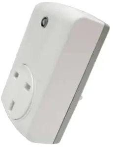
This AN301 plug-in ON/OFF Module is a transceiver which is a Z-WaveTM enabled device and is fully compatible with any Z-WaveTM enabled network. Z-WaveTM enabled devices displaying the Z-WaveTM logo can also be used with it regardless of the manufacturer, and ours can also be used in other manufacturer’s Z-WaveTM enabled networks. Remote On/Off control of the connected load is possible with other manufacturer’s Wireless Controller. Each module is designed to act as a repeater. Repeaters will re-transmit the RF signal to ensure that the signal is received by its intended destination by routing the signal around obstacles and radio dead spots.
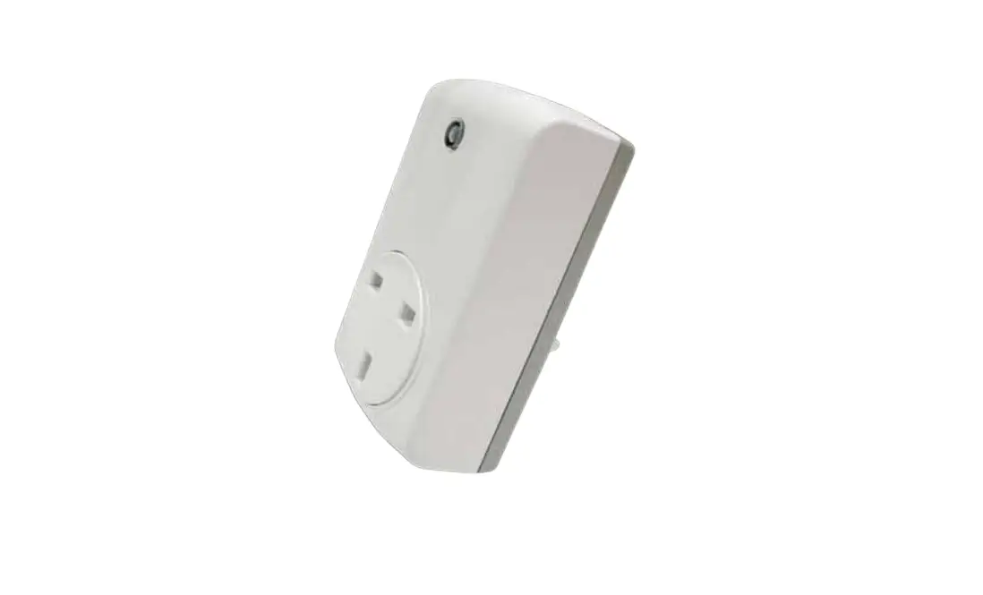
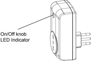
Product Overview
Adding to Z-WaveTM Network
The unit supports SmartStart function, where inclusion is initiated automatically on power-on, and repeated at dynamic intervals for as long as the device is not included into a Z-Wave network. Z-Wave SmartStart is based on the embedded SDK 6.8x and requires related gateway software components.
If the gateway does not support SmartStart function, this device can be added to the Z-Wave network using manual inclusion, or by scanning the DSK QR code or entering a 5-digit Device Specific Key (DSK) when requested by the gateway.
Installation
- Plug this On/Off Module into a wall outlet near the load to be controlled.
- Plug the load into the Module. Make sure the load to be controlled cannot exceed 2990/2200 watts.
- Press the button or switch on the load to the ON position.
- To manually turn ON the Module, press and release the On/Off button. The LED will turn ON, and the load plugged into the Module will also turn ON.
- To manually turn OFF the Module, simply press and release the On/Off button.
The LED will turn OFF and the load plugged into the Module will also turn OFF.
Programming
Z-Wave Group Support
The unit supports two association groups with 1 node support for Grouping 1 and 5 nodes support for Grouping 2. This has the effect that when the unit is operating, all devices associated with the unit will receive the relevant reports.
- When the unit is powered for the first time, the unit will send a Notification
Report to the node of Group 1. - When setting the unit or changing the unit’s status, the unit will send a Binary
Switch Report to the node of Group 1. - When performing Reset the unit will send Device Reset Locally Notification to
the node of Group1. - When the button on the unit or the wall switch is pressed, the unit will send a
Basic Set command to the nodes of Group 2. When the unit is OFF, Basic Set Value = 0x00. When the unit is ON, Basic Set Value = 0xFF.
Z-Wave Plus Info
| Role Type | Node Type | Installer Icon | User Icon |
| Slave Always On | Z-Wave Plus node | On/Off Power Switch | On/Off Power Switch |
Version
| Protocol Library | 3 (Slave_Enhance_232_Library) |
| Protocol Version | 6.07 (SDK 6.81.06) |
| Firmware 0 Version | 1V0 |
Manufacturer
| Manufacturer ID | Product Type | Product ID |
| 0x0060 | 0x0004 | 0x000F |
AGI (Association Group Information) Table
| Group | Profile | Command Class & Command (List) N bytes | Group Name(UTF-8) |
| 1 | General | Binary Switch Report, | Lifeline |
| Notification Report, Device Reset Locally Notification | |||
| 2 | Control | Basic Set | On/Off control (Button1) |
Basic commands
| Command | Description |
| Basic Get | Inquire about the status of the device |
| Basic Report | Report the status of the device. |
| Basic Set | Set the status of the device.(Value=0XFF (ON), 0x00 (OFF)) |
Notification
| Event | Type | Event | Event Parameters Length |
| Power applied for first time | 0x08 | 0x01 | 0x00 |
Configuration
The configurable values are as following:
Remember the last status:
| Parameter Number | Size | Range | Default |
| 3 | 1 | 1/0 | 1: remember (0: do not remember) |
Command Classes
The module supports Command Classes including…
- COMMAND_CLASS_ZWAVEPLUS_INFO_V2
- COMMAND_CLASS_VERSION_V2
- COMMAND_CLASS_MANUFACTURER_SPECIFIC_V2
- COMMAND_CLASS_DEVICE_RESET_LOCALLY_V1
- COMMAND_CLASS_ASSOCIATION_V2
- COMMAND_CLASS_ASSOCIATION_GRP_INFO_V1
- COMMAND_CLASS_MULTI CHANNEL ASSOCIATION V2
- COMMAND_CLASS_TRANSPORT SERVICE V2
- COMMAND_CLASS_POWERLEVEL_V1
- COMMAND_CLASS_SECURITY
- COMMAND_CLASS_SECURITY 2
- COMMAND_CLASS_SUPERVISION
- COMMAND_CLASS_NOTIFICATION_V8
- COMMAND_CLASS_CONFIGURATION_V1
- COMMAND_CLASS_SWITCH_BINARY_V1
- COMMAND_CLASS_FIRMWARE_UPDATE_MD_V4
Additional Command Classes Supported
- Power Level: For test purpose during product installation.
- Binary Switch: Refer to Basic.
- Firmware Update: For OTA function.
Troubleshooting
The table below lists the several steps involved when adding or removing the detector from the Z-Wave network.
| Action/Status | Description | LED indication |
| No node ID | The Z-Wave Controller does not allocate a node ID to the unit. | 2-second on, 2-second off |
| Auto Inclusion | The power is applied for the first time and no node ID has been stored in the module, or after executing reset. | |
| Inclusion | Put the Z-Wave Controller into inclusion mode. | |
| Press the link key three times within 1.5 seconds to put the unit into inclusion mode. | ||
| Exclusion | Put the Z-Wave Controller into exclusion mode. | |
| Press the link key three times within 1.5 seconds to put the unit into exclusion mode. | ||
| Reset (This procedure should only be used when the network primary controller is inoperable.) | Press the link key three times within 1.5 seconds to put the unit into exclusion mode. | |
| Within 1 second of step 1, press link key again and hold until LED is off (about 5 seconds). | ||
| Node ID is excluded. The device reverts to factory default state and will be in auto-inclusion mode for 4 minutes. | ||
| ※ Failed or successful results in including/excluding the ID can be viewed on the Z-Wave Controller. | ||
Note: If you are connecting this unit to a Z-Wave Controller that utilizes the S2
security protocol, you may be asked to enter a 5 digit Device Specific Key (DSK)
that is unique to each unit by your controller. This can be found in one of two
places:
- on the QR code label on the back of the unit
- on the insert card inside the packaging
| Symptom | Cause of Failure | Recommendation |
| Device not responding and LED not displaying | The device is not connected to the mains power correctly | Check if connection is correct, or voltage is too high or too low |
| Device malfunction | Send the device to be repaired | |
| LED displaying, but cannot control On/Off status of connected load | The connected load has its own on/off switch | Turn the switch of the connected load to On. |
| Can press button to control, but cannot control by RF | RF interference is occurring. Someone nearby might be emitting | Wait for a while and retry the operation |
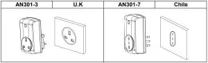
Socket Type
Refer to the outline for each socket suited for each country as follows:
Specification
Operating Voltage | 230V/50Hz |
| Maximum Load | 2990W for UK, 2200W for Chile |
Range | 70 m line of sight |
| Frequency Range | 868.42 MHz(UK)/921.42MHz(Chile) |
Specifications are subject to change and improvement without notice.
Warning
- Do not dispose of electrical appliances as unsorted municipal waste, use separate collection facilities.
- Contact your local government for information regarding the collection systems available.
- If electrical appliances are disposed of in landfills or dumps, hazardous substances can leak into the groundwater and get into the food chain, damaging your health and well-being.
- When replacing old appliances with new once, the retailer is legally obligated to take back your old appliance for disposal at least for free of charge.


 Asp-3-1-00 Manual")


 6a-pl-vab-a0 Manual")


