
SICK RMS1000 Radar Sensors

QUICK START
About this document
The purpose of this Quickstart is to allow you to commission the product quickly and easily.
Supplementary and other relevant documents:
- Safety notes, printed copy included
- RMS1000 operating instructions, available for download
- RMS1000 “Regulatory Notes” technical information, printed copy included and available for download
- RMS1000 Telegram Listing, available for download
Documents available for download and additional information, such as application examples and associated software, can be found on the SICK product page on the Internet at: www.sick.com/RMS1000
All rights reserved. Subject to change without notice.
Safety information
Intended use
The RMS1000 radar sensor is used for area monitoring. Within a defined detection area, the sensor detects static and moving objects, and triggers a switching signal upon detection of a corresponding object.
Distance zones can be defined and these zones can be assigned various functions.
The distance and speed of the objects within the detection area are determined and provided via the data telegram.
All object data can be provided via Ethernet. The ability to provide it via
CAN J1939 is under development.
The device is operated via the SOPASair software from SICK AG.
NOTE
The radar sensor is approved for operation in countries listed in the RMS1000 “Regulatory Notes” technical information (no. 8026123). This document is included with the device. The operation of the device in other countries can interfere with protected frequency ranges.
- Only use the device in countries in which it has been approved.
- When reselling the device, inform the buyer about the regional approval restrictions.
SICK AG assumes no liability for losses or damage arising from the use of the product, either directly or indirectly. This applies in particular to use of the product that does not conform to its intended purpose and is not described in this docu‐mentation.
Product description
Scope of delivery
The delivery of the device includes the following components:
| No. of units | Component | Note |
| 1 | Device in the version ordered | Without connecting cables and brackets |
| 1 | SOPASair configuration soft‐ ware | integrated into the device, access via web browser |
| 1 | Protective caps for electrical connections | Included or possibly attached to the device |
| 1 | Printed RMS1000 “Regulatory Notes” technical information (no. 8026123) | Informs about the countries for which an approval exists. Names country-specific aspects which are to be taken into account during operation of the device. Enclosed and also available at www.sick.com/ 8026123 |
| 1 | Printed safety notes, multilin‐ gual | Brief information and general safety notes |
Connections and LEDs
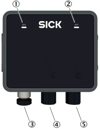
Figure 1: Connections and LEDs
- LED 1 Device (Dev)
- LED 2 Application (App)
- Connection Ethernet
- Connection CAN I/O
- Connection Power
Connections
For details, see Connection diagram, page 2.
LEDs
The LEDs indicate the following status information.
| Device status | LED 1 Device (Dev) 1 LED 2 Application (App) 1 | Description |
| Device off |  | Off Off |
| Initialization phase |  | Permanently red Permanently red |
| Parameteriza‐ tion |  | Permanently red Permanently red |
| Field clear 2 |  | Permanently green Permanently green |
| Object detec‐ tion 2 |  | Permanently green Permanently yellow |
| No field created |  | Permanently green Off |
| Error (can be remedied by the customer) |  | Slowly flashing red Slowly flashing red Synchronous |
| Serious error (contact SICK Service) |  | Quickly flashing red Quickly flashing red Synchronous |
| Standby/save electricity |  | Permanently yellow Permanently red |
| Firmware update |  | Slowly flashing red Slowly flashing green Asynchronous |
- Colors:
 Patterns:
- The LEDs indicate the status of the object detection or evaluation in a field. The LEDs do not indicate the status of the digital output. If the result of the field evaluation is inverted before being placed on the digital output, this has no effect on the LEDs.
 Patterns:
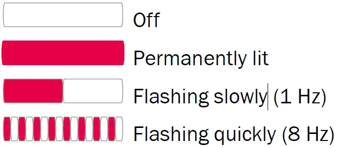
Mounting
Mounting instructions
- Observe the technical data.
- Protect the sensor from direct sunlight.
- To prevent condensation, avoid exposing the device to rapid changes in temperature.
- The mounting site has to be designed for the weight of the device.
- It should be mounted so that it is exposed to as little shock and vibration as possible. Optional mounting accessories are available, see Accessories, page 2.
- The 4 threaded mounting holes on the left and right side of the housing are used to mount the device on a bracket. Only use screws with M5 thread.
Insert the screws into the thread by a maximum of 9 mm. - Use of a weather hood and a mounting bracket is recommended for outdoor installations. Information about optional accessories, Accessories, page 2.
- Do not mount device tilted toward the ground in order to prevent ground reflections, which could be detected as objects.
- No detection is possible within the blind zone. The blind zone is specified in the technical data.
Electrical installation
Wiring instructions
NOTE
Pre-assembled cables can be found online at:
NOTICE
Faults during operation and device or system defects!
Incorrect wiring may result in operational faults and defects.
- Follow the wiring notes precisely.
The enclosure rating stated in the technical data is achieved only with screwed plug connectors or protective caps.
Isolate the wires of unused digital outputs at the control cabinet.
All circuits connected to the device must be designed as ES1 circuits. The voltage source must meet the requirements of ES1 and PS2 (EN 62368-1).
Connect the connecting cables in a de-energized state. Do not switch on the supply voltage until installation is complete and all connecting cables are connected to the device and control.
Use suitable connecting cables and connectors for the application and ambient conditions, see Accessories, page 2.
The supply voltage must be as specified in the technical data.
The voltage supply via a power supply unit must be capable of buffering a brief power failure of up to 20 ms.
Prevent product damage caused by shortcircuit: The device supply voltage input is equipped with reverse polarity protection. The internal functional earth is directly connected to the metal housing of the device. The internal functional earth also corresponds to the negative pole of the supply voltage.
Connection diagram
Ethernet
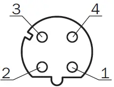
Pin assignment for Ethernet connection
| Male/female connector | Pin | Short form | Signal description |
| M12 female connector, 4-pin D-coded
| 1 | TX+ | Transmit data positive |
| 2 | RX+ | Receive data positive | |
| 3 | TX- | Transmit data negative | |
| 4 | RX- | Receive data negative |
CAN I/O
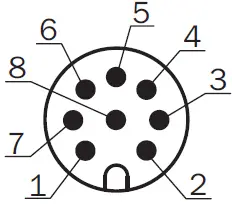
Pin assignment for CAN I/O connection
| Male/female connector | Pin | Short form | Signal description |
| M12 male connector, 8-pin A- coded
| 1 | CAN H | CAN high |
| 2 | CAN L | CAN low | |
| 3 | IN2 | Input 2 | |
| 4 | GND IN1/2 | Earth input 1/2 | |
| 5 | OUT2 | Output 2 | |
| 6 | OUT3 | Output 3 | |
| 7 | GND | Earth | |
| 8 | OUT4 | Output 4 |
Power
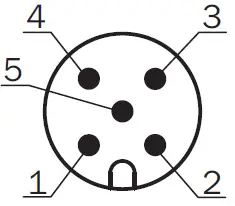
Pin assignment Power connection
| Male/female connector | Pin | Short form | Signal description |
| M12 male connector, 5-pin A- coded
| 1 | L+ | Supply voltage: +9 V DC … +32 V DC |
| 2 | IN1 | Input 1 | |
| 3 | GND | Earth | |
| 4 | OUT1 | Output 1 | |
| 5 | GND IN1/2 | Earth input 1/2 |
Connecting the device electrically
- Ensure the voltage supply is not connected.
- Connect the device according to the connection diagram, Connection diagram, page 2.
- Switch on the supply voltage.
Operation
General advice
The device works fully automatically in normal operation and requires no operator intervention.
Switching off and on
- To switch off the device, disconnect the device from the voltage supply.
The device switches off. The device configuration remains unchanged, measured values are lost. - Connect the device to the voltage supply.
The device starts with the last saved configuration data.
Configuration
Parameterize the device using the SOPASair configuration software. Opening user interface:
- Start web browser (recommendation: Google Chrome).
- Enter the device IP address into the address line. The following IP address is pre-configured by default: 192.168.0.1.
The SOPASair user interface appears.
Technical data (excerpt)
NOTE
The relevant online data sheet for your product, including technical data, dimensional drawing, and connection diagrams, can be downloaded, saved, and printed from the Internet:
Features
| Measurement principle | FMCW |
| Radio equipment appro‐ val | For country-specific restrictions see “Regulatory Compliance Information” (no. 8021596) technical information (downloads), also included with the product |
| Frequency band | RMS-A (ETSI): 61 GHz … 61.5 GHz RMS-C (Japan): 60.5 GHz … 61 GHz RMS-E (FCC): 61 GHz … 61.5 GHz |
| Transmitting power | < 20 dBm (e.i.r.p.) |
| Aperture angle | Horizontal: ± 60° Vertical: ± 4° |
| Working range | 0.4 m … 100 m |
| Blind zone | 0.00 m…. 0.4 m |
| Detection capability | At 1 m² RCS 1: 50 m At 10 m² RCS 2: 100 m |
| Distance accuracy | 1 m² RCS 1 to 20 m: 0.04 m 1 m² RCS 2 to 50 m: 0.1 m |
| Distance resolution | 0.4 m |
| Speed Range | -30 m/s … +30 m/s |
| Speed resolution | 0.625 m/s |
| Speed accuracy | 1 m² to 20 m: 0.0625 m/s 1 m² to 50 m: 0.15 m/s |
- Typical radar cross-section value for a pedestrian.
- Typical radar cross-section value for a car.
Working ranges based on distance
| Distance [m] | ||||||||
| 1 | 5 | 10 | 20 | 40 | 60 | 80 | 100 | |
| Vertical | 0.1 | 0.7 | 1.4 | 2.8 | 5.6 | 8.4 | 11.2 | 14.0 |
| Horizontal | 3.5 | 17.3 | 34.6 | 69.3 | 138.6 | 207.8 | 277.1 | 346.4 |
Mechanics/Electronics
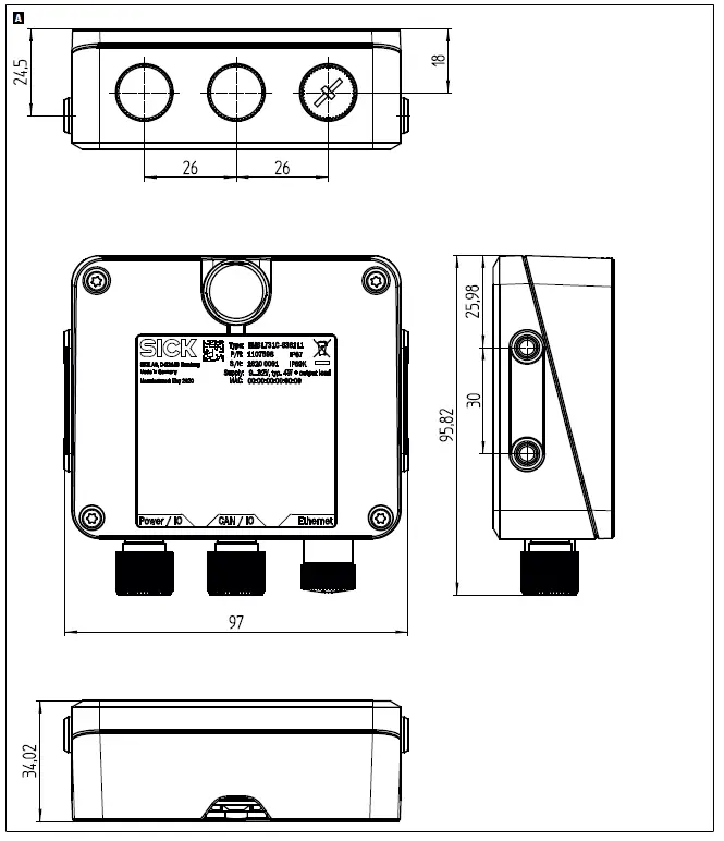
Dimensional drawing
Dimensional drawing RMS1000: A
Accessories
NOTE
Accessories and, if applicable, mounting information can be found online at:


