neptronic Compact Make-up Air Unit
Introduction
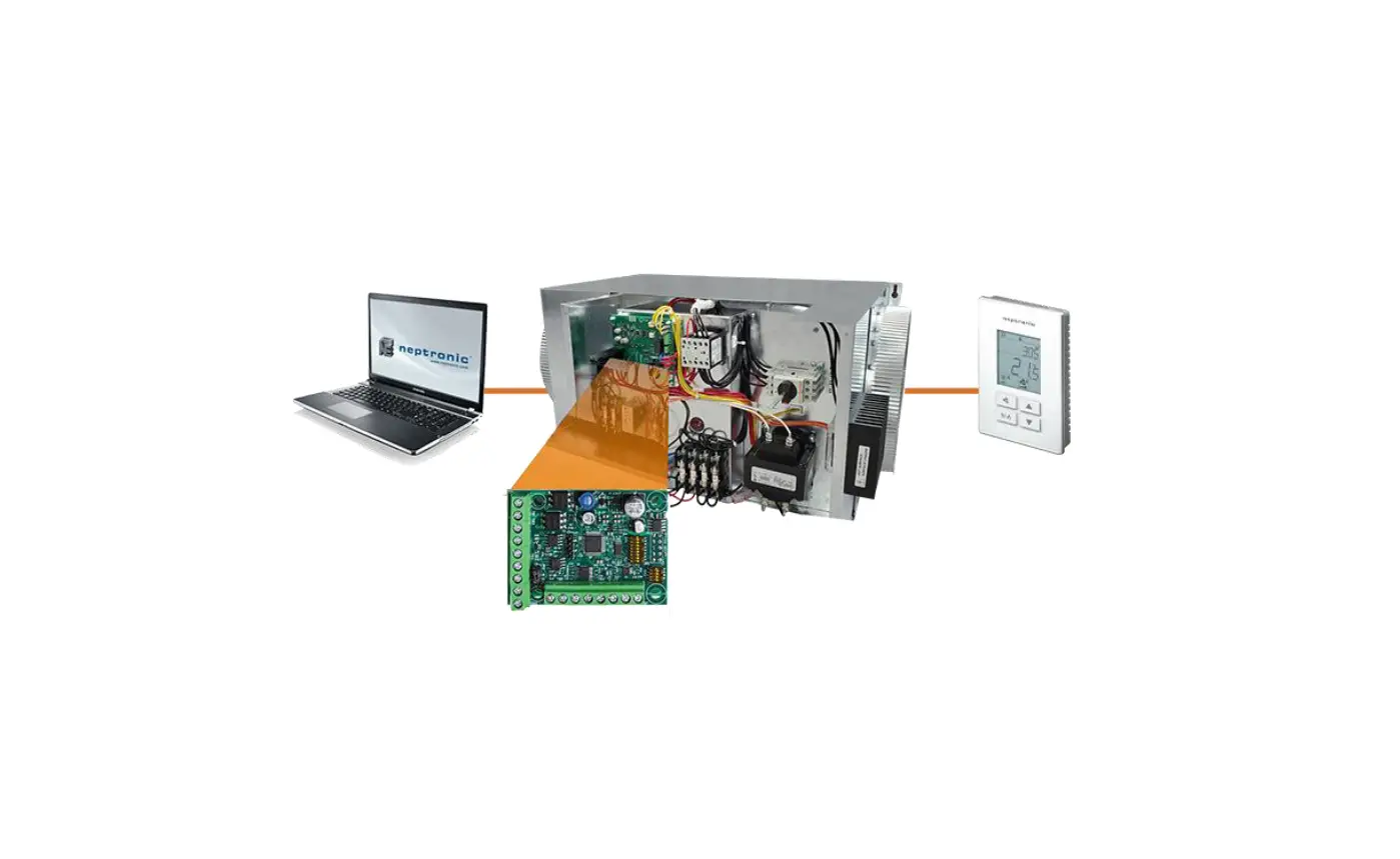
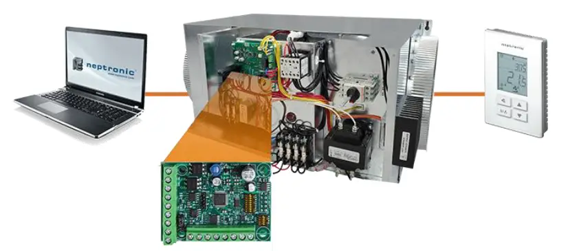
The CMU Compact Make-up Air Unit BACnet Communication Module User Guide provides information about using the CMU Compact Make-up Air Unit with BACnet communications feature. The BACnet communication protocol for building automation and control networks enables communication between client devices within a network. The controller provides a BACnet network interface between BACnet client devices and Neptronic Controller series devices. It uses the BACnet Master Slave/Token Passing (MS/TP) protocol at the BACnet MAC layer.
Pre-requisites
The BACnet communication user guide assumes that you are familiar with the concepts of BACnet and its terminology.
Advantages of BACnet
BACnet enabled controllers have the following advantages:
- Quick Message Transmission. The controller uses a synchronous implementation for BACnet messages making it quick and efficient. Each BACnet confirmed service request is answered as quickly as possible without using the Reply Postponed frame. The MS/TP implementation is performed within Tusage_delay of 15 minutes to ensure a Tusage_timeout value within 20 minutes.
- MS/TP Support. The controller supports a Full Master Node state machine for MS/TP. Max_Master and the instances are configured to the device object through BACnet WriteProperty service. The MAC address is set via the DIP switches. Programming mode determines the MS/TP baud rate setting of 9600, 19200, 38400, and 76800. In the configuration mode, the device is configured through the device’s keypad. For more information about the WriteProperty, refer to Table 3 – Object Types Supported.
- BIBB Support. The controller functions the same way as the B-ASC type profile server and supports the specific BIBB as per their relevant definitions.
- DS-RP-B
- DS-RPM-B
- DS-WP-B
- DS-WPM-B
- DM-DCC-B
- DM-DDB-B
- DM-DOB-B
- DM-RD-B
- DM-TS-B
- DM-UTC-B
- DS-COV-B
- DS-COVP-B
- SCHED-WS-I-B
- Object Support. The controller supports a fixed list of BACnet visible values, which appear as Present_Values of various BACnet standard object types in addition to a device object. For more information, refer to Table 3 – Object Types Supported.
- Alarms. The controller supports indication of various alarm conditions through value changes in properties of several objects. However, it does not generate BACnet event notifications.
BACnet Properties Configuration
To establish communication on the network and guarantee a unique ID of devices in a BACnet system, the following properties may have to be configured.
Table 1 – BACnet Properties Configuration
| Property | Default Value | Configuration |
| MAC Address | 000 | Set to a value between 000 and 127 via DIP switches. Can also be set to a value between 000 and 254 via menu. The values from 128-254 represent MS/TP non-token passing slave devices. |
|
Device Instance |
Auto | · The controller automatically configures its device instance to 153,000 + MAC address. · The value can be set manually via the menu. · The value can be set manually through the WriteProperty service to Device Object.Object_Identifier. · The device’s Object_Identifier is a combination of the Device Object_Type (8) and the Device_Instance (0-4194302), therefore its decimal or hexadecimal representation tends to be incomprehensible. · For example, the Device_Instance=1000 has an equivalent Object_Identifier of 0x020003E8 hexadecimal or 33555432 decimal. |
| Baud Rate | 0 = Auto | · The controller configures its baud rate automatically by detecting the network upon connection. · The value can be set manually from the available values of Auto, 9600, 19200, 38400, 76800. |
|
Max_Master |
127 | · Configure Max_Master value to increase network efficiency when there are less than 127 devices on the network. · The Max_Master value can be changed via menu or through the WriteProperty service to the Device Object.Max_Master. For more information, refer to the MAC Address and Max_Master section. |
| Device Object.Object_Name | Name of the device | · Configure the name of the device through WriteProperty service to the Device Object.Object_Name. For example, CMU. |
Configuration Options
The following Configuration options enable you to configure and run the BACnet features of the controllers quickly.
Quick Setup
Configure the controller’s baud rate and device instance without programming.
- Set a unique MAC address using the DIP switches located on the controller.
- Connect the controller to the network and power it up.
- The controller automatically configures the baud rate and device instance.
- Repeat the steps for each controller.
Manual Setup
To use a Device_Instance other than 153,000, and/or if your site has more than one controller network, go to the menu using the TDF digital room sensor.
- Ensure that the TDF digital room sensor jumper is in the RUN position.
- Press the
 and
and buttons simultaneously for 5 seconds. The “Enter Password” screen appears.
 - Enter the 637 password within 1 minute by using the arrow keys to increase or decrease the value and theandbuttons to toggle between the digits.
- Follow the menus to configure the Baud Rate, MAC address, Max Master, and Device Instance manually.
- Disconnect the power to the controller, connect the controller to the network, and connect the power again.
Configure the Max_Master value through WriteProperty service to the Device Object.Max_Master to increase network efficiency or if there are less than 127 devices on the network.
MAC Address and Max_Master
The MAC address must be unique on the entire MS/TP network. However, having a unique MAC address and a high baud rate does not guarantee efficient operation of the controller and other MS/TP units on the MS/TP network. Some MAC address and Max_Master combinations are more efficient than others. BACnet requires token-passing units to occasionally “poll” for other masters based on the MAC address and Max_Master.
A poor combination of MAC addresses and Max_Master can lead to a slower network due to lost time polling for masters that are not present. Unless there are 126 other units on the MS/TP network, the default Max_Master value of 127 is not the most efficient choice for the controller. The Max_Master default value of 127 was selected to ensure that any master, specifically a BACnet client can be found when the controller is initially started.
Examples of MAC Address and Max_Master Configurations
The following are some of the examples to indicate the optimum combination of Mac address and Max_Master configurations to ensure a quick and efficient output.
Example 1
- MAC=0. Max_Master=127
- MAC=1, Max_Master=127
This configuration is slow and inefficient because every time either unit is required to find another master unit, it has to poll 126 units until it finds the right one to pass the token.
Example 2
- MAC=0. Max_Master=5
- MAC=1 to MAC=4 are not used
- MAC=5, Max_Master=5
This configuration is better than Example 1 but it is still slower. The Max_Master is set to the most efficient value but the gap between the two MAC addresses is high. Therefore, each unit must poll four units until it finds the right one to pass the token.
Example 3
- MAC=0. Max_Master=1
- MAC=2, Max_Master=2
This is an incorrect configuration. The MAC=0 will never find MAC=2 because it will never poll for the master MAC address=2.
Example 4
- MAC=0. Max_Master=3
- MAC=1, Max_Master=3
- MAC=2, Max_Master=3
- MAC=3, Max_Master=3
This is an efficient configuration as the units are numbered consecutively and the Max_Master is set to the most efficient value. As a general guideline, the most efficient setup for an MS/TP network is one in which the units are consecutively numbered starting at MAC address 0 and having Max_Master=the maximum MAC address in the system. If consecutive numbering is not possible, then the next most efficient setup is one in which all units have Max_Master=the maximum MAC address in the system.
Copy Config
Copy and broadcast the entire configuration of a controller to controllers of same type using the Copy Config feature.
- Access Operation Mode (jumper set to RUN position).
- Press and hold both function buttons for 5 seconds to access the Quick Access menu.
- Enter the password, 637.
- Scroll to Copy Config programming menu and select Yes. Follow the rest of the onscreen instructions.
Note: A Copy Config can also be executed via BACnet. See AV.165, AV.166, AV.167, and BV.90 in Table 6 – Object Table Information: Analog Value (AV) and Table 9 – Object Table Information: Binary Value (BV) for details.
However, the BACnet Schedule is not copied during a Copy Config operation.
Network Reset
Reset the controller via BACnet using the Reinitialize Device service. The Reinitialize Device service can be accessed using the following password: nep.
The Reinitialize Device service has two types of reset such as:
- Warm Reset. The Warm Reset restarts the controller with actual configuration.
- Cold Reset. The Cold Reset restarts the controller with Factory configuration.
Warning: The Cold Reset erases the actual configuration when setting the MSTP address. Therefore, exercise caution while performing a Cold Reset.
Device Object Properties
The following table lists all the BACnet properties supported for the device object. The W indicates that the property is writable using the BACnet WriteProperty service.
Table 2 – Device Object Properties
| Property | Value | Writable | |
| Object_Identifier | · Programmable where the instance part of the Object_Identifier is in the range of 0-4194302 · The device instance must be unique system-wide · The default value for the device instance=153003 (Vendor_Identifier*1000) | W | |
| Object_Name | MU@irCOM, programmable up to 32 bytes | W | |
| Description | Programmable up to 32 characters | W | |
| Object_Type | Device | ||
| System_Status | Operational | ||
| Vendor_Identifier | Always 153 | ||
| Vendor_Name | Always Neptronic | ||
| Model_Name | Example, CMU-COM | Read Only | |
| Firmware_Revision | currently, 1.02 | Read Only | |
| Application_Software_Version | currently, 1.77 | Read Only | |
| Protocol_Version | Always 1 | Read Only | |
| Protocol_Revision | Always 14 | Read Only | |
| DataBase_Revision | Default: 77, incremented if Object Name and/or device ID change | Read Only | |
| Max_APDU_Length_Accepted | Always 480 | Read Only | |
| Segmentation_Supported | (3) = No Segmentation | Read Only | |
| APDU_Timeout | 6000 | W | |
| Number_of_APDU_Retries | Always 3 | Read Only | |
| Local_Time | 00:00:00 | W | |
| Local_Date | 01-Jan-2020 (Thu) | W | |
| UtC_Offset | -300 minutes | W | |
| Daylight_Savings_Status | False | W | |
| Backup_Failure_Timeout | 300 | W | |
| Configuration_Files | File-1 | ||
| Last_Restore_Time | 2020-01-01 (Thu), 00:00:00:00 | ||
| Backup_And_Restore_State | IDLE | ||
| Backup_Preparation_Time | 0 | ||
| Restore_Completion_Time | 0 | ||
| Restore_Preparation_Time | 0 | ||
|
Protocol_Services_Supported | · subscribeCOV · atomicReadFile · atomicWriteFile · readProperty · readPropertyMultiple · WriteProperty · writePropertyMultiple · deviceCommunicationControl | · reinitializeDevice · unconfirmedPrivateTransfer · timeSynchronization · who-Has · who-Is · UtcTimeSynchronization · subscribeCOVProperty | |
|
Protocol_Object_Types_Supported | · analog-input · analog-output · analog-value · binary-input · binary-output · binary-value | · device · file · program · schedule · multi-state-value | |
| Object_List | 134 | Read Only | |
| Device_Address_Binding | Always empty | ||
| Max_Master | Programmable in the range of 1-127 (default: 127) | W | |
| Max_Info_Frames | Always 1 | ||
| Proprietary property #1000 | · Represents the MS/TP MAC address in the range of 0 to 254 (default: 0) · Writable if all MAC address DIP switches are off · Values 128 to 254 represent MS/TP non-token passing slave devices | W | |
| Property | Value | Writable |
| Proprietary property #1001 | · Programmable (default: Auto) · Represents the MS/TP Baud rate (unsigned type) · Values are 0 (auto), 9600, 19200, 38400, 57600, 76800 · Reading this property always returns the actual Baud rate | W |
| Proprietary property #1002 | · Programmable (default: 15 minutes) · Represents the period of time that an object in/out of service will automatically return to normal. Range = 0-120 minutes (unsigned type) · Writing 0 means no automatic return to normal | W |
Object Types Supported
The following table lists all the BACnet properties supported for each object type. Most of the properties are locked. The exception is Present_Value, which represents the dynamic operating values of the device, and the Status_Flag, Event_State, and Reliability properties, which reflect the availability of the Present_Value. Unless otherwise specified, properties are not changeable.
Table 3 – Object Types Supported
| Object Type | Enabled | Optional Properties Supported | Writable Properties | Notes |
| Note: Writable properties are different for some objects. Refer to the respective Object Table information to know the writable property for objects. | ||||
|
Analog Input |
R |
· Reliability · Description · Min_Present_Value · Max_Present_Value · Resolution · COV-Increment |
· Out_of_Service · COV-Increment | · If “Out of Service” is true, Present_Value and Status_Flag become writable properties. · Out_of_Service property is writable for objects to which Present_Value is not writable. · Refer to Out of Service Property section on page 7 for more information. · Object will automatically return to Normal after a programmable period of time. Refer to Proprietary property #1002 of Device Object in Table 2 – Device Object Properties. |
|
Analog Value |
R |
· Reliability · Description · COV-Increment · Priority_Array · Relinquish_Default |
· Present_Value · Out_of_Service · COV-Increment | · Present_Value property is writable for every AV object unless indicated. · Out_of_Service property is writable for objects indicated in Table 6 – Object Table Information: Analog Value (AV) on page 9. · Refer to Out of Service Property section on page 7 for more information. · Object will automatically return to Normal after a programmable period of time. Refer to Proprietary property #1002 of Device Object in Table 2 – Device Object Properties. Some objects are commandable. In such case, the priority-array and relinquish-default properties are available. |
|
Analog Output |
R | · Description · Reliability · Min-Pres-Value · Max-Pres-Value · Resolution · COV-Increment | · Present_Value · COV-Increment | |
|
Binary Input |
R |
· Reliability · Active_Text · Inactive_Text · Description |
Out_of_Service | · If “Out of Service” is true, Present_Value and Status_Flag become writable properties. · Out_of_Service property is writable for objects to which Present_Value is not writable. · Refer to Out of Service Property section on page 7 for more information. · Object will automatically return to Normal after a programmable period of time. Refer to Proprietary property #1002 of Device Object in Table 2 – Device Object Properties. |
|
Binary Value |
R | · Reliability · Active_Text · Inactive_Text · Description · Priority_Array · Relinquish_Default |
Present_Value | · Present_Value property is writable for every Binary Value object. · Object automatically returns to Normal after a programmable time. Refer to Proprietary property #1002 of Device Object in Table 2 – Device Object Properties. |
| Object Type | Enabled | Optional Properties Supported | Writable Properties | Notes |
| Binary Output | R | · Description · Reliability · Inactive-text · Active-text | Present_Value | |
|
Device |
R |
· Max_Master · Max_Info_Frame · Description · Active-COV-subscriptions · #1000 (MSTP addr) · #1001 (Baud rate) · #1002 (Time out) · Local_Time · Local_Date · Uts_Offset · Daylight_Savings_Status · Apdu_Timeout · Backup_Failure_Timeout | · Object_Identifier · Object_Name · Max_Master · Description · Local_Time · Local_Date · Uts_Offset · Daylight_Savings_Status · Apdu_Timeout · Backup_Failure_Timeout · #1000 · #1001 · #1002 · Configuration_Files · Last_Restore_Time · Backup_And_Restore_State · Backup_Preparation_Time · Restore_Completion_Time · Restore_Preparation_Time | Refer to Table 2 – Device Object Properties on page 5. |
| Multi- State Value | R | · Description · Reliability · States_Text | Present_Value | · Present_Value property is writable for every Multi State Value object unless indicated. · Out_of_Service property is not writable for MSV. |
| Program | R | · Description · Reliability | Program_Change | · Only LOAD and RESTART are supported for Program Change. · Use LOAD to apply the new firmware. |
| File | R | Description | · Archive · File Size | Only 0 is the accepted value to be written to file size. |
|
Schedule |
R | · Description · Weekly Schedule | · Effective Period · Weekly Schedule · Schedule Default · Priority For Writing · Out_of_Service | If “Out of Service” is true, Present_Value becomes writable property. |
Out-of-Service Property
Neptronic controllers offer the use of the Out of Service writable property. When the value of this property is set to True, it disconnects the object from the physical input, enabling you to input other values. This is useful for special applications or while troubleshooting. For example, you can ignore the temperature read from a sensor and input the desired temperature value in order to perform specific tests.
For security reasons, a timeout will set the Out of Service property back to False after 15 minutes. This value can be modified to between 0 and 120 minutes (For more information, see proprietary property #1002 in Table 2 – Device Object Properties).
Object Table Information
The CMU uses the following BACnet object tables, categorized on the basis of their ID. The type is the BACnet Object type, the instance is the BACnet Object. Together, the type and instance form the BACnet Object_Identifier for an object according to the following C-language algorithm:
- object_identifier=(unsigned long)((unsigned long)type<<22)+instance
Analog Input (AI)
Table 4 – Object Table Information: Analog Input (AI)
| ID | Name | List | Description | W? | Notes |
| AI.1 | AI1_Voltage | Integrator | Displays the actual voltage of analog input 1 in Vdc. | Out of service COV Increment | 0 to 10V, Resolution: 0.001V |
| AI.2 | AI2_Voltage | Integrator | Displays the actual voltage of analog input 2 in Vdc. | Out of service COV Increment | 0 to 10V, Resolution: 0.001V |
| AI.3 | AI3_Temperature | Integrator | Displays the actual temperature read by the sensor on analog input 3. | Out of service COV Increment | -40°C to 85°C or -40°F to 185°F, Resolution: 0.01°C or 0.018°F |
| AI.4 | AI4_Temperature | Integrator | Displays the actual temperature read by the sensor on analog input 4. | Out of service COV Increment | -40°C to 85°C or -40°F to 185°F, Resolution: 0.01°C or 0.018°F |
| AI.5 | Room Air Temperature | Integrator | Displays the room temperature reading value. | Read only COV Increment | 0°C to 50°C or 32°F to 122°F, Resolution: 0.01°C or 0.018°F |
| AI.6 | Room Air Relative Humidity | Integrator | Displays the room relative humidity reading value. | Read only COV Increment | 0 to 100%RH, Resolution: 0.1%RH |
| AI.7 | CO2Level | Integrator | Displays the reading of the CO2 sensor. | Read only COV Increment | 0 to 2000 PPM, Resolution: 1 PPM |
| AI.8 | VOCIndex | Integrator | Displays the reading of the VOC sensor. | Read only COV Increment | 0 to 65535, Resolution: 1 |
| AI.9 | LuminousFlux | Integrator | Displays the reading of the light sensor. | Read only COV Increment | 0 to 16000 Lux, Resolution: 1 Lux |
| AI.10 | CMUOnBoardTempSetpoint | Integrator | Displays the temperature setpoint value from the CMU on-board potentiometer. Only available when MSV.17 is set to (1) OnBoard. | Read only COV Increment | 0°C to 35°C or 32°F to 95°F, Resolution: 0.01°C or 0.018°F |
| Al.11 | CMUIntake | Integrator | Displays the CMU air intake temperature. | Read only COV Increment | -40°C to 85°C or -40°F to 185°F, Resolution: 0.01°C or 0.018°F |
| AI.12 | CMUOuttake | Integrator | Displays the CMU air outtake temperature. | Read only COV Increment | -40°C to 85°C or -40°F to 185°F, Resolution: 0.01°C or 0.018°F |
| AI.13 | CMUBoardTempeature | Integrator | Displays the temperature value of the CMU main printed circuit board. | Read only COV Increment | -40°C to 85°C or -40°F to 185°F, Resolution: 0.01°C or 0.018°F |
| AI.14 | CMUSSRTemp | Integrator | Displays the temperature value measured on the solid-state relay. | Read only COV Increment | -40°C to 85°C or -40°F to 185°F, Resolution: 0.01°C or 0.018°F |
Analog Output (AO)
Table 5 – Object Table Information: Analog Output (AO)
| ID | Name | List | Description | W? | Notes |
| AO.1 | AO1_Voltage | Integrator | Commands the voltage on analog output 1 in Vdc. This object is commandable with priority array. | Present Value COV Increment | 0 to 10V, Resolution: 0.001V |
| AO.2 | AO2_Voltage | Integrator | Commands the voltage on analog output 2 in Vdc. This object is commandable with priority array. | Present Value COV Increment | 0 to 10V, Resolution: 0.001V |
Analog Value (AV)
Table 6 – Object Table Information: Analog Value (AV)
| ID | Name | List | Description | W? | Notes |
| AV.1 | SAT | Integrator | Displays the Supply Air Temperature (SAT) reading. | Read only COV Increment | 0°C to 100°C or 32°F to 212°F, Resolution: 0.01°C or 0.018°F |
| AV.2 | SARH | Integrator | Displays the Supply Air Relative Humidity (SARH) reading. | Read only COV Increment | 0 to 100%RH, Resolution: 0.01%RH |
| AV.3 | OAT | Integrator | Displays the Outside Air Temperature (OAT) reading. Available when any of the analog inputs on the add-on board are configured as an outside air temperature sensor. | Read only COV Increment | 0°C to 100°C or 32°F to 212°F, Resolution: 0.01°C or 0.018°F |
| AV.4 | OARH | Integrator | Displays the Outside Air Relative Humidity (OARH) reading. Available when any of the analog inputs on the add-on board are configured as an outside air humidity sensor. | Read only COV Increment | 0 to 100%RH, Resolution: 0.01%RH |
| AV.5 | DuctStaticPressure | Integrator | Displays the static pressure value in the duct. Available when any of the analog inputs on the add-on board are configured as a static pressure sensor and connected to the Neptronic SPD sensor. | Read only COV Increment | 0 to 1250Pa, Resolution: 0.1Pa |
| AV.6 | ModulatingDamperFeedback | Integrator | Displays the feedback value corresponding to the modulating damper position. Available when any of the analog inputs on the add-on board are configured as damper feedback. When configured as damper feedback, the CMU waits for the feedback before turning on the fan or heating, as a safety interlock. | Read only COV Increment | 0 to 100%, Resolution: 1% |
| AV.7 | CurrentAirflowSetpoint | Integrator | Configuration value of the airflow setpoint value as a percentage of the maximum capacity (fan speed setpoint). This object is commandable with priority array. | Present Value COV Increment | 0 to 100%, Resolution: 1% |
| AV.8 | CMUFanRPM | Integrator | Displays the ECM fan speed RPM value. Only available for units with an ECM fan. | Read only COV Increment | 0 to 10000 PPM, Resolution: 1 PPM |
| AV.9 | CMUHeaterStage1DutyCycle | Integrator | Displays the duty cycle of the heater vernier stage 1 when there is a demand for heating, provided there are no alarms that prevent the unit from heating or operating normally. | Read only COV Increment | 0 to 100%, Resolution: 0.1% |
| AV.10 | NetworkTempSetpoint | Integrator | Configuration value of the temperature setpoint set over the network. | Present Value COV Increment | 0°C to 35°C or 32°F to 212°F, Resolution: 0.01°C or 0.018°F |
| AV.11 | TstatTempSetpoint | Integrator | Configuration value of the temperature setpoint set using the TDF. | Present Value COV Increment | 0°C to 35°C or 32°F to 212°F, Resolution: 0.01°C or 0.018°F |
| ID | Name | List | Description | W? | Notes |
| AV.12 | Cfg_CMUAntiFreezeSetpoint | Advanced | Configuration value of the CMU anti-freeze temperature setpoint. This object is commandable with priority array. | Present Value COV Increment | 0°C to 35°C or 32°F to 212°F, Resolution: 0.01°C or 0.018°F |
| AV.13 | Cfg_OccAirflowSetpoint | Advanced | Configuration value of the airflow setpoint in percentage of the maximum capacity when in Occupied mode. | Present Value COV Increment | 0 to 100%, Resolution: 1% |
| AV.14 | Cfg_UnoccAirflowSetpoint | Advanced | Configuration value of the airflow setpoint in percentage of the maximum capacity when in Unoccupied mode. | Present Value COV Increment | 0 to 100%, Resolution: 1% |
| AV.15 | Cfg_BI3_StageWeight | Advanced | Configuration value of the signal stage weight for binary input 3 in percentage of the full range. | Present Value COV Increment | 0 to 100%, Resolution: 1% |
| AV.16 | Cfg_BI4_StageWeight | Advanced | Configuration value of the signal stage weight for binary input 4 in percentage of the full range. | Present Value COV Increment | 0 to 100%, Resolution: 1% |
| AV.17 | Cfg_ExhaustFanDelay | Advanced | Configuration value of the exhaust fan start time delay. | Present Value COV Increment | 1 to 255 seconds, Resolution: 1 second |
| AV.18 | Cfg_ExhaustFanMinRange | Advanced | Configuration of the minimum value of the exhaust fan control signal. | Present Value COV Increment | 0 to 10V, Resolution: 0.001V |
| AV.19 | Cfg_ExhaustFanMaxRange | Advanced | Configuration of the maximum value of the exhaust fan control signal. | Present Value COV Increment | 0 to 10V, Resolution: 0.001V |
| AV.20 | Cfg_DamperDelay | Advanced | Configuration value of the damper stroke time delay. | Present Value COV Increment | 0 to 255 seconds, Resolution: 1 second |
| AV.21 | Cfg_OccupanyInputMinTime | Advanced | Configuration value of the occupancy input minimum time. | Present Value COV Increment | 0 to 240 minutes, Resolution: 1 minute |
| AV.22 | Cfg_TstatTempSetpointMin | Advanced | Configuration of the minimum value of the temperature setpoint set using the TDF. | Present Value COV Increment | 0°C to 35°C or 32°F to 212°F, Resolution: 0.01°C/0.018°F |
| AV.23 | Cfg_ TstatTempSetpointMax | Advanced | Configuration of the maximum value of the temperature setpoint set using the TDF. | Present Value COV Increment | 0°C to 35°C or 32°F to 212°F, Resolution: 0.01°C/0.018°F |
| AV.24 | Cfg_DryModeSetpoint | Advanced | Configuration value of the relative humidity setpoint in dry mode. | Present Value COV Increment | 10 to 90%RH, Resolution: 0.1%RH |
| AV.25 | Cfg_DryModeDeadBand | Advanced | Configuration value of the deadband for the relative humidity setpoint in dry mode. | Present Value COV Increment | 1 to 10%RH, Resolution: 0.1%RH |
| AV.26 | Cfg_DryModeAntiCycleDelay | Advanced | Configuration value of the anti-cycle time delay in dry mode. | Present Value COV Increment | 0 to 720 minutes, Resolution: 1 minute |
| AV.27 | Cfg_DuctOccStaticPressureSe tpoint | Advanced | Configuration value of the static pressure control loop setpoint in the duct when in occupied mode. | Present Value COV Increment | 0 to 1250Pa, Resolution: 0.1Pa |
| AV.28 | Cfg_DuctUnoccStaticPressure SetPoint | Advanced | Configuration value of the static pressure control loop setpoint in the duct when in unoccupied mode. | Present Value COV Increment | 0 to 1250Pa, Resolution: 0.1Pa |
| AV.29 | Cfg_CO2Setpoint | Advanced | Configuration value of the maximum limit of CO2 concentration before the unit sends an alarm. | Present Value COV Increment | 0 to 1000 PPM, Resolution: 1 PPM |
| AV.30 | Cfg_CO2DeadBand | Advanced | Configuration value of the deadband for the maximum limit of CO2 concentration. | Present Value COV Increment | 0 to 200 PPM, Resolution: 1 PPM |
| AV.31 | Cfg_SATOffset | Advanced | Configuration value of the Supply Air Temperature offset. | Present Value COV Increment | -5°C to 5°C or -9°F to 9°F, Resolution: 0.01°C or 0.018°F |
| AV.32 | Cfg_ SARHOffset | Advanced | Configuration value of the Supply Air Relative Humidity offset. | Present Value COV Increment | -5 to 5%RH, Resolution: 0.1%RH |
| ID | Name | List | Description | W? | Notes |
| AV.33 | Cfg_OATOffset | Advanced | Configuration value of the Outside Air Temperature offset. | Present Value COV Increment | -5°C to 5°C or -9°F to 9°F, Resolution: 0.01°C or 0.018°F |
| AV.34 | Cfg_OARHOffset | Advanced | Configuration value of the Outside Air Relative Humidity offset. | Present Value COV Increment | -5 to 5%RH, Resolution: 0.1%RH |
| AV.35 | Cfg_RATOffset | Advanced | Configuration value of the Room Air Temperature offset. | Present Value COV Increment | -10°C to 10°C or -18°F to 18°F, Resolution: 0.01°C or 0.018°F |
| AV.36 | Cfg_ RARHOffset | Advanced | Configuration value of the Room Air Relative Humidity offset. | Present Value COV Increment | -5 to 5%RH, Resolution: 0.1%RH |
| AV.37 | Cfg_DuctStaticPressureOffset | Advanced | Configuration value of the duct static pressure offset. | Present Value COV Increment | -125 to 125Pa, Resolution: 0.1Pa |
| AV.38 | Cfg_FactoryMinFanSpeed | Factory | Configuration value of the minimum fan speed. | Present Value COV Increment | 0 to 100%, Resolution: 1% |
| AV.39 | Cfg_TempControlPropBand | Factory | Configuration value of the temperature control proportional band. | Present Value COV Increment | 0.5°C to 20°C or 33°F to 68°F, Resolution: 0.1°C or 0.18°F |
| AV.40 | Cfg_TempControlIntTime | Factory | Configuration value of the temperature control integral time. | Present Value COV Increment | 0 to 255 seconds, Resolution: 1 second |
| AV.41 | Cfg_TempControlDerivTime | Factory | Configuration value of the temperature control derivative time. | Present Value COV Increment | 0 to 255 seconds, Resolution: 1 second |
| AV.42 | Cfg_StaticPressurePropBand | Factory | Configuration value of the static pressure control proportional band. | Present Value COV Increment | 0 to 250Pa, Resolution: 1Pa |
| AV.43 | Cfg_StaticPressureIntTime | Factory | Configuration value of the static pressure control integral time. | Present Value COV Increment | 0 to 255 seconds, Resolution: 1 second |
| AV.44 | Cfg_StaticPressureDerivTime | Factory | Configuration value of the static pressure control derivative time. | Present Value COV Increment | 0 to 255 seconds, Resolution: 1 second |
| AV.45 | Cfg_SATControlBand | Integrator | Configuration value of the Supply Air Temperature control band. | Present Value COV Increment | 2°C to 10°C or 36°F to 50°F, Resolution: 0.01°C or 0.018°F |
| AV.46 | SynchroTimeoutCount | Factory | Configuration value of the synchronization timeout counter. | Present Value COV Increment | 0 to 65535, Resolution: 1 |
| AV.47 | NoHeatDetectionDeadband | Integrator | Configuration value of the No Heat Detection deadband. | Present Value COV Increment | 2°C to 8°C or 36°F to 46°F, Resolution: 0.01°C or 0.018°F |
| AV.48 | NoHeatDetectionDelay | Integrator | Configuration value of the No Heat Detection time delay. | Present Value COV Increment | 30 to 240 seconds, Resolution: 1 second |
Binary Input (BI)
Table 7 – Object Table Information: Binary Input (BI)
| ID | Name | List | Description | W? | Notes |
| BI.1 | BI3_State | Integrator | Contact status of analog input 3/binary input 3: (0) Open, (1) Close. | Out of service | 0 = Open, 1 = Close |
| BI.2 | BI4_State | Integrator | Contact status of analog input 4/binary input 4: (0) Open, (1) Close. | Out of service | 0 = Open, 1 = Close |
| BI.3 | OccupancySensor | Integrator | Status value on whether the occupancy sensor has detected movement. | Read only | 0 = No, 1 = Yes |
| BI.4 | CMUOnOffInput | Integrator | Status value of the state of the CMU on/off input contact. | Read only | 0 = Off, 1 = On |
Binary Output (BO)
Table 8 – Object Table Information: Binary Output (BO)
| ID | Name | List | Description | W? | Notes |
| BO.1 | BO1_State | Integrator | Contact status of binary output 1: (0) Open, (1) Close. This object is commandable with priority array. | Present Value | 0 = Open, 1 = Close |
| BO.2 | BO2_State | Integrator | Contact status of binary output 2: (0) Open, (1) Close. This object is commandable with priority array. | Present Value | 0 = Open, 1 = Close |
Binary Value (BV)
Table 9 – Object Table Information: Binary Value (BV)
| ID | Name | List | Description | W? | Notes |
| BV.1 | ExhaustFanState | Integrator | Status value for the state of the exhaust fan. | Read only | 0 = Off, 1 = On |
| BV.2 | OnOffDamperState | Integrator | Status value for the state of the on/off damper. | Read only | 0 = Closed, 1 = Open |
| BV.3 | OnOffDamperFeedback | Integrator | Status value for the state of the on/off damper feedback. | Read only | 0 = Closed, 1 = Open |
| BV.4 | CMUFanEnable | Integrator | Status value to indicate whether the CMU fan has been enabled. | Read only | 0 = No, 1 = Yes |
| BV.5 | CMUHeaterStage2State | Integrator | Status value for the state of the second heater stage. | Read only | 0 = Off, 1 = On |
| BV.6 | Cfg_BI3ContactType | Advanced | Configuration to change the contact’s normal position for binary input 3. Input can be set to (0) Normally Opened or (1) Normally Closed. | Present Value | 0 = NO, 1 = NC |
| ID | Name | List | Description | W? | Notes |
| BV.7 | Cfg_BI4ContactType | Advanced | Configuration to change the contact’s normal position for binary input 4. Input can be set to (0) Normally Opened or (1) Normally Closed. | Present Value | 0 = NO, 1 = NC |
| BV.8 | Cfg_BO1ContactType | Advanced | Configuration to change the contact’s normal position for binary output 1. Output can be set to (0) Normally Opened or (1) Normally Closed. | Present Value | 0 = NO, 1 = NC |
| BV.9 | Cfg_BO2ContactType | Advanced | Configuration to change the contact’s normal position for binary output 2. Output can be set to (0) Normally Opened or (1) Normally Closed. | Present Value | 0 = NO, 1 = NC |
| BV.10 | Cfg_TstatTempSetpointLock | Advanced | Configuration value to lock the temperature setpoint on the TDF. | Present Value | 0 = No, 1 = Yes |
| BV.11 | Cfg_ScheduleEnable | Advanced | Configuration to activate the schedule. The schedule is configurable via BACnet or Modbus. If no schedule is configured, the mode will always be occupied. The time and day will be displayed on the unit. | Present Value | 0 = No, 1 = Yes |
| BV.12 | Cfg_UnitSelection | Advanced | Configuration value to select between the metric and imperial unit system. | Present Value | 0 = Metric, 1 = Imperial |
| BV.13 | Cfg_OccupancyInputsEnable | Advanced | Configuration value to enable or disable the occupancy inputs. | Present Value | 0 = No, 1 = Yes |
| BV.14 | Cfg_DryMode | Advanced | Configuration value to enable or disable the dry mode. | Present Value | 0 = Disable, 1 = Enable |
| BV.15 | Cfg_CO2ExtractMode | Advanced | Configuration value to enable or disable the CO2 extract mode. | Present Value | 0 = Disable, 1 = Enable |
| BV.16 | Cfg_StaticPressureLoop | Advanced | Configuration value to enable or disable the static pressure loop. | Present Value | 0 = Disable, 1 = Enable |
| BV.17 | Cfg_OccupanyInputsInactiveMode | Advanced | Configuration value to set the occupancy mode when inactive to either the (0) Unoccupied or (1) Off state. | Present Value | 0 = Unoccupied, 1 = Off |
| BV.18 | SystemOnOff | Integrator | Configuration value to turn the system on or off. | Present Value | 0 = Off, 1 = On |
| BV.19 | HostThermalCutoutAlarm | Integrator | Status value to indicate whether the Thermal Cutout alarm has been triggered. | Read only | 0 = Off, 1 = On |
| BV.20 | HostCommTimeoutAlarm | Integrator | Status value to indicate whether the Communication Timeout alarm has been triggered, indicating that the CMU main board is not receiving any communication from the add-on board. | Read only | 0 = Off, 1 = On |
| BV.21 | HostSSRCutoutAlarm | Integrator | Status value to indicate whether the SSR Cutout alarm has been triggered. | Read only | 0 = Off, 1 = On |
| BV.22 | HostBoardCutoutAlarm | Integrator | Status value to indicate whether the Board Cutout alarm has been triggered. | Read only | 0 = Off, 1 = On |
| BV.23 | HostSSOR1Alarm | Integrator | Status value to indicate whether the SSOR1 Sensor alarm has been triggered. | Read only | 0 = Off, 1 = On |
| BV.24 | HostSSOR2Alarm | Integrator | Status value to indicate whether the SSOR2 Sensor alarm has been triggered. | Read only | 0 = Off, 1 = On |
| BV.25 | HostBoardTempAlarm | Integrator | Status value to indicate whether the Board Temperature Sensor alarm has been triggered. | Read only | 0 = Off, 1 = On |
| BV.26 | HostSSRTempAlarm | Integrator | Status value to indicate whether the SSR Temperature Sensor alarm has been triggered. | Read only | 0 = Off, 1 = On |
| BV.27 | HostFanTempAlarm | Integrator | Status value to indicate whether the Fan Temperature Sensor alarm has been triggered. | Read only | 0 = Off, 1 = On |
| BV.28 | HostAirFlowDetectAlarm | Integrator | Status value to indicate whether the Airflow Sensor alarm has been triggered. | Read only | 0 = Off, 1 = On |
| ID | Name | List | Description | W? | Notes |
| BV.29 | HostInvalidConfigAlarm | Integrator | Status value to indicate whether the Invalid Board Configuration alarm has been triggered. | Read only | 0 = Off, 1 = On |
| BV.30 | HostNoHeatDetectionAlarm | Integrator | Status value to indicate whether the No Heat Detection alarm has been triggered by the CMU main board, indicating that the heater is not working properly. | Read only | 0 = Off, 1 = On |
| BV.31 | HostFrequencySynchronisationError | Integrator | Status value to indicate whether there is a frequency synchronisation error, indicating that the heater is not working properly. | Read only | 0 = Off, 1 = On |
| BV.32 | DamperBlockedAlarm | Integrator | Status value to indicate whether the Damper Blocked alarm has been triggered. | Read only | 0 = Off, 1 = On |
| BV.33 | SATNotDetectedAlarm | Integrator | Status value to indicate whether the No Supply Air Temperature Input alarm has been triggered. | Read only | 0 = Off, 1 = On |
| BV.34 | RATNotDetectedAlarm | Integrator | Status value to indicate whether the No Room Air Temperature Input alarm has been triggered. | Read only | 0 = Off, 1 = On |
| BV.35 | TimeoutCommAlarm | Integrator | Status value to indicate whether the Timeout Communication alarm has been triggered, indicating that the add-on board is not receiving any communication from the CMU main board. | Read only | 0 = Off, 1 = On |
| BV.36 | AI1NotConnected | Integrator | Status value to indicate whether analog input 1 is connected or not, which would otherwise trigger an alarm. | Read only | 0 = Off, 1 = On |
| BV.37 | AI2NotConnected | Integrator | Status value to indicate whether analog input 2 is connected or not, which would otherwise trigger an alarm. | Read only | 0 = Off, 1 = On |
| BV.38 | NoHeatDetectionAlarm | Integrator | Status value to indicate whether the No Heat Detection alarm has been triggered by the CMU add-on board, indicating that the heater is not working properly. | Read only | 0 = Off, 1 = On |
| BV.39 | ECMFanFeedbackHostAlarm | Integrator | Status value to indicate whether the ECM Fan Feedback alarm has been triggered, indicating that the feedback value does not correspond to the setpoint. | Read only | 0 = Off, 1 = On |
| BV.40 | Cfg_AutoPID | Factory | Configuration value to enable or disable Auto PID. | Present Value | 0 = No, 1 = Yes |
Multi State Value (MSV)
Table 10 – Object Table Information: Multi State Value (MSV)
| ID | Name | List | Description | W? | Notes |
| MSV.1 | OccupancyState | Integrator | Status that indicates the state of actual occupancy. Occupied: Zone is occupied. Unoccupied: Zone is not occupied. Off: Occupancy mode is turned off. | Read only | Occupied Unoccupied Off |
| MSV.2 | Cfg_ObjectListMode | Integrator | Configuration value to select the category of BACnet objects to display. | Present Value | Integrator Advanced Factory |
| ID | Name | List | Description | W? | Notes |
|
MSV.3 |
Cfg_AI1_Mode |
Advanced | Configuration value for the mode of Analog Input 1. This input accepts a 0-10Vdc signal. Off: The input is not used. SAT: The input is used for the supply air temperature sensor. SARH: The input is used for the supply air relative humidity sensor. OAT: The input is used for the outside air temperature sensor. OARH: The input is used for the outside air relative humidity sensor. StaticPressure: The input is used for a static pressure sensor meant to control the unit and maintain the setpoint. FanSetpoint: The input is used as an external 0-10Vdc control setpoint for the fan speed. This option is applicable only for ECM fans. DamperFeedback: The input is used as feedback to monitor a modulating damper connected to the unit. |
Present Value |
Off SAT SARH OAT OARH StaticPressure FanSetpoint DamperFeedback |
|
MSV.4 |
Cfg_AI2_Mode |
Advanced |
Same description as MSV.3 |
Present Value | Off SAT SARH OAT OARH StaticPressure FanSetpoint DamperFeedback |
|
MSV.5 |
Cfg_AI3_BI3_Mode |
Advanced | Configuration value for the mode of Analog input 3/Binary input 3. This input accepts a 10K Type 3 or dry contact signal. Off: The input is not used. SAT: The input is used for the supply air temperature sensor. OAT: The input is used for the outside air temperature sensor. DamperFeedback: is used as feedback to monitor an on/off damper connected to the unit. Occupancy: The input is used for occupancy detection. FanSpeedStage: The input is used to change the stage of the CMU fan speed when used with multiple exhaust fans. It requires the SIH-150 to be connected with the exhaust fan and wired back to the unit. |
Present Value |
Off SAT OAT DamperFeedback Occupancy FanSpeedStage |
|
MSV.6 |
Cfg_AI4_BI4_Mode |
Advanced |
Same description as MSV.5 |
Present Value | Off SAT OAT DamperFeedback Occupancy FanSpeedStage |
|
MSV.7 |
Cfg_AO1_Mode |
Advanced | Configuration value for the mode of Analog output 1. Provides a 0-10Vdc signal. Off: The output is not used. ExhaustFan: The output is used for an exhaust fan proportional to the CMU fan speed. Damper: The output is used for modulating inlet dampers which will open or close based on the CMU run status. |
Present Value | Off ExhaustFan Damper |
| MSV.8 | Cfg_ AO2_Mode | Advanced | Same description as MSV.7 | Present Value | Off ExhaustFan Damper |
| ID | Name | List | Description | W? | Notes |
|
MSV.9 |
Cfg_BO1_Mode |
Advanced | Configuration value for the mode of Binary output 1. Provides a dry contact signal. Off: The output is not used. ExhaustFan: The output is used to initiate the exhaust fan when the CMU starts. Damper: The output is used to open or close an inlet damper based on the command to enable or turn on/off the CMU. |
Present Value | Off ExhaustFan Damper |
| MSV.10 | Cfg_ BO2_Mode | Advanced | Same description as MSV.9 | Present Value | Off ExhaustFan Damper |
| MSV.11 | Cfg_StaticPressureSensorRange | Advanced | Select the range of the static pressure sensor in Pascal. | Present Value | 250 500 1250 |
| MSV.12 | Cfg_AI1_SignalRange | Advanced | Configuration value to select the signal type range for analog input 1. | Present Value | 2-10Vdc 0-10Vdc |
| MSV.13 | Cfg_AI2_SignalRange | Advanced | Configuration value to select the signal type range for analog input 2. | Present Value | 2-10Vdc 0-10Vdc |
| MSV.14 | Cfg_AO1_SignalRange | Advanced | Configuration value to select the signal type range for analog output 1. | Present Value | 2-10Vdc 0-10Vdc |
| MSV.15 | Cfg_AO2_SignalRange | Advanced | Configuration value to select the signal type range for analog output 2. | Present Value | 2-10Vdc 0-10Vdc |
| MSV.16 | Cfg_TempControlSource | Advanced | Configuration value of the temperature control source. SAT: The source will be provided from the supply air temperature sensor connected to the AI on the add-on board. RAT: The source will be provided from the room temperature sensor (TDF). | Present Value | SAT RAT |
| MSV.17 | Cfg_TempSetpointSource | Integrator | Configuration value of the temperature setpoint source. OnBoard: The source will be provided from the on-board potentiometer. Tstat: The source will be provided from the TDF. Network: The source will be provided from the value written over the network. | Present Value | OnBoard Tstat Network |
|
MSV.18 |
Cfg_AdditionalDisplay |
Advanced | Configuration value of the second line of display on the TDF. None: No value is displayed. Time: It displays the current time in the machine. CO2: It displays the CO2 reading (only applicable if TDF with CO2 sensor is used). SARH: It displays the supply air relative humidity (if connected and configured). RAT: It displays the room temperature value. |
Present Value | None Time CO2 SARH RAT |
| ID | Name | List | Description | W? | Notes |
|
MSV.19 |
Cfg_TemperatureDisplayed |
Integrator | Configuration value of the temperature value to display. Default: Defaults to the sensor selected for control. Alternate: The value displayed alternates between the value on the TDF and the duct sensor (CMU outtake). SAT: The value displayed is the supply air temperature reading configured on the add-on board. Tstat: The value displayed is the room temperature reading measured on the TDF. |
Present Value |
Default Alternate SAT Tstat |
|
MSV.20 |
Reset_reason |
Advanced |
Displays the reason for the previous system reset. |
Read only | noReason independent watchdog window watchdog software reset power-down |
Other
Table 11 – Object Table Information: Other
| ID | Name | List | Description | W? | Notes |
| FIL.1 | CMU-COM Update | Advanced | Firmware binary file. Set the File Size to 0 to erase the previous binary file before uploading a new one. Use only the binary file provided by Neptronic. | File Size Archive | File Size is accepted for 0 value only. |
| PGM.1 | CMU-COM Process | Advanced | Program firmware. Set to LOAD to program the file in application memory. The controller will be reset and the firmware will be LOADED into the memory. Use only the binary file provided by Neptronic. | Program Change | Program Change, only LOAD (1) and RESTART (4) are supported. |
|
SCH.1 |
OccupancySchedule |
Integrator | Weekly occupancy schedule to specify which occupancy state is active during specific periods of day. | Weekly Schedule Schedule Default Priority for Writing Effective Period Out of Service |
400 Lebeau blvd, Montreal, Qc, H4N 1R6, Canada
www.neptronic.com
Toll free in North America: 1-800-361-2308 Tel.: (514) 333-1433 Fax: (514) 333-3163 Customer service fax: (514) 333-1091
Monday to Friday: 8:00am to 5:00pm (Eastern time)


