![]()
![]() Dolphin WAVE 30 Commercial Pool Cleaner Robot
Dolphin WAVE 30 Commercial Pool Cleaner Robot
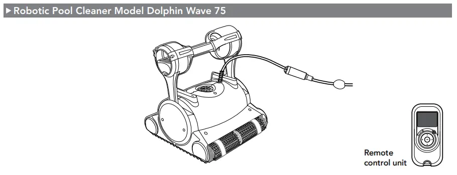
Instruction Manual Robotic Pool Cleaner Dolphin Wave 75 Operating Instructions
INTRODUCTION
Thank you for purchasing a Maytronics Robotic Pool Cleaner.
We are sure that your Maytronics Robotic Pool Cleaner will provide you with reliable, convenient and cost effective pool cleaning. Its reliable filtration in all pool conditions and all-surface climbing brush enhance maximum pool hygiene.
The Robotic Pool Cleaners by Maytronics deliver advanced cleaning technology, long lasting performance and easy maintenance.
SPECIFICATIONS
Motor protection: IP 68 Minimum depth: 0.4 m (1.33 ft) Maximum depth: 5 m (16.4 ft)
WARNINGS AND CAUTIONS
3.1 Warnings
 Use the originally supplied power supply only
- Ensure the electrical outlet is protected by a ground fault interrupter (GFI) or an earth leakage interrupter (ELI)
- Keep the power supply out of standing water
- Position the power supply at least 3.5 m (12 ft) away from the edge of the pool
- Do not enter the pool while the pool cleaner is working
- Unplug the power supply before servicing
- Keep the Robotic Pool Cleaner out of the reach of children or persons with reduced physical, sensory, or mental capabilities, or lack of experience and knowledge, unless they have been given supervision or instruction.
3.2 Cautions
When not in use store the Pool Cleaner on the Caddy in a shaded area.
Use the Pool Cleaner in the following water conditions only:
| Chlorine | 4 ppm max. |
| pH | 7.0 – 7.8 |
| Temperature | 6°C – 35°C (43°F – 95°F) |
| NaCl | 5000 ppm max. |
POOL CLEANER PARTS
USING THE POOL CLEANER
5.1 Set Up
Attach the floating cable to the power supply by inserting it with the notch on the connector (1) lined up with the groove in the socket on the power supply and turning clockwise (2).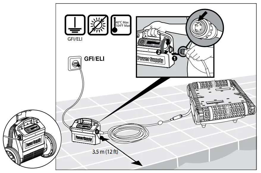
5.2 Putting the Pool Cleaner into the pool
If Wonder brush/ Wonder rings are dry, soak them in water until soft. Shake the robot from side to side or turn it upside down to release trapped air. Let it sink to the pool floor.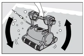 Turn the power supply ON.
The Pool Cleaner will now operate until it has reached the end of the cleaning cycle.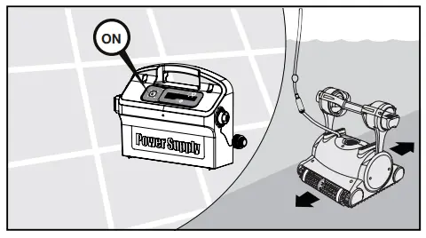 5.3 Removing the Pool Cleaner from the pool
The robot will perform automatic shut-off at the end of the cleaning cycle.

![]() Turn OFF and unplug the power supply.
Turn OFF and unplug the power supply.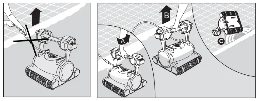
Using the floating cable, bring the Pool Cleaner to the pool’s edge.
Using the handle remove the Pool Cleaner from the pool.![]() DO NOT PULL THE POOL CLEANER FROM THE POOL USING THE CABLE.
DO NOT PULL THE POOL CLEANER FROM THE POOL USING THE CABLE.
5.4 Maintenance
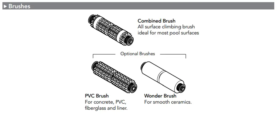
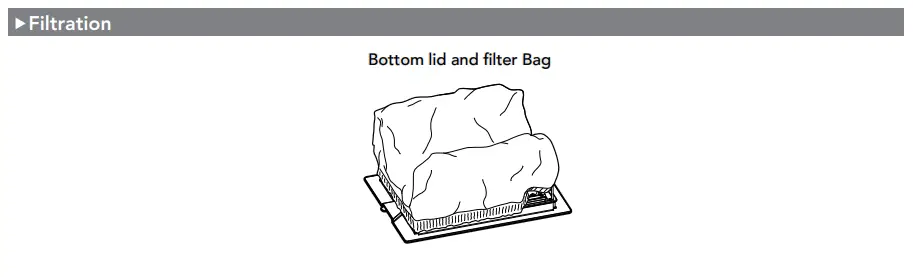
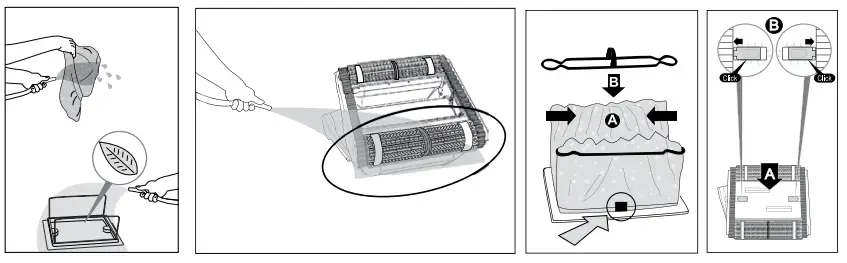
Filter bag
Clean the filter bag with a hose. Periodically clean the brushes with a hose. It is recommended to periodically wash the filter bag in a washing machine. Use gentle cycle program.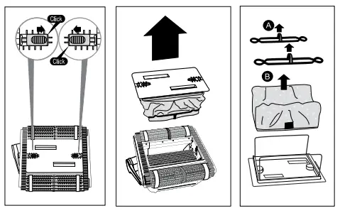
 Cleaning the impeller
![]() Unplug the power supply.
Unplug the power supply.
If you notice debris trapped in the impeller open the impeller and remove the debris. 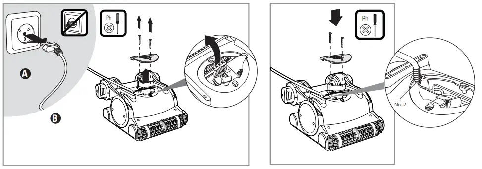 Cable
Cable
To remove the kinks, stretch the cable out completely and let it sit for at least a day in the sun.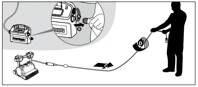 5.5 Off-season storage
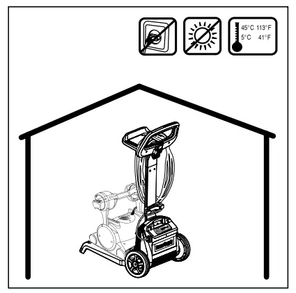
If the pool cleaner will not be in use for an extended period, perform the following storage steps:
- Make sure that no water is left in the pool cleaner.
- Thoroughly clean the filter bag and insert in place.
- Roll up the cable so that it has no kinks and place on the Caddy.
- Store the pool cleaner upright on the Caddy in a protected area out of direct sun/rain/frost at a temperature of between 5°C – 45°C (41°F – 113°F).
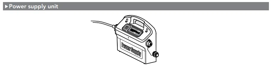
POWER SUPPLY
Digital “Switch-Mode” Power Supply with full filter bag and delay indicator.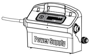
- Input – 100 VAC – 250 VAC
- 50 Hz – 60 Hz
- 180 W
- Output – <30 VDC
- IP 54
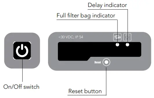
![]() Full filter bag indicator and Reset button
Full filter bag indicator and Reset button
The power supply is equipped with a filter bag status indicator.
The red LED indicates two filter conditions.
- When blinking – The filter is partially blocked.
- When lighted – The filter is blocked and must be emptied and cleaned.
If the LED does not turn off after the filter bag had been emptied and cleaned, press the RESET button while the robot is working.![]() Delay indicator
Delay indicator
The power supply is equipped with a Delay indicator that indicates if the Delay option is activated (through the remote control unit).
REMOTE CONTROL UNIT
The remote control unit offers two operation modes – Automatic mode and manual direction control mode.
In automatic mode, the cleaning parameters can be changed.
In manual direction mode, the robot’s motion can be controlled manually.
The Control Panel 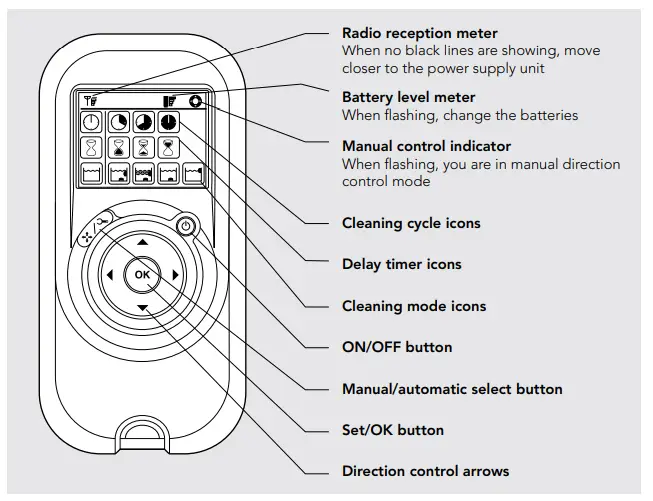 Manual Direction Control Mode
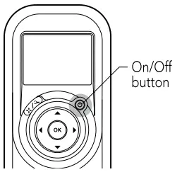 | 1. Press the On/Off button once. The remote control will start in manual direction control mode. 2. Use the direction control arrows (see right) to control the movement of the robot around the pool. | 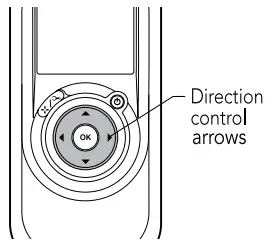 |
Exiting Manual Direction Control Mode and setting the Automatic Mode
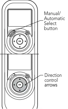 | 1. To exit the manual direction control mode, press the Manual/Automatic select button once only. 2. The digital screen will light up and three rows of function icons will be displayed in default mode. | 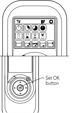 |
| 1. To change the parameters press the up or down arrows. 2. To select the parameter settings use the right or left arrows. When you reach the required function press the Set/OK button. |
Press the Manual/Automatic select button and then choose the desired parameters according to the following table:
 Cleaning cycle Cleaning cycleindicator This determines the length of the cleaning cycle. |  Fast Fast2-hour cycle |  Fast Fast2-hour cycle |  Extra Extra4-hour cycle | |
 Delay time Delay timeindicator This determines when the pool cleaner starts to work. Delaying allows the dirt to settle to the bottom of the pool. | (Default setting) |  One-hour delay One-hour delay |  Two-hour delay Two-hour delay | |
 Cleaning action Cleaning actionindicator Allowing you to choose from the following options. |  Standard StandardFloor and wall cleaning. (Default setting) |  Ultra-clean Ultra-cleanStronger suction and slower movement. (floor and wall) |  Floor only Floor onlyCleans only the floor and the area where the floor and walls meet |  Walls only Walls onlyCleans walls and waterline only |
Note:
- After 2 minute if no button is pressed, the Remote Control Unit will shut-down and the Pool cleaner will continue to work in the previous settings.
- When the “Ultra-Clean” and “Walls Only” options finish their cycles, the Pool Cleaner will return to default settings.
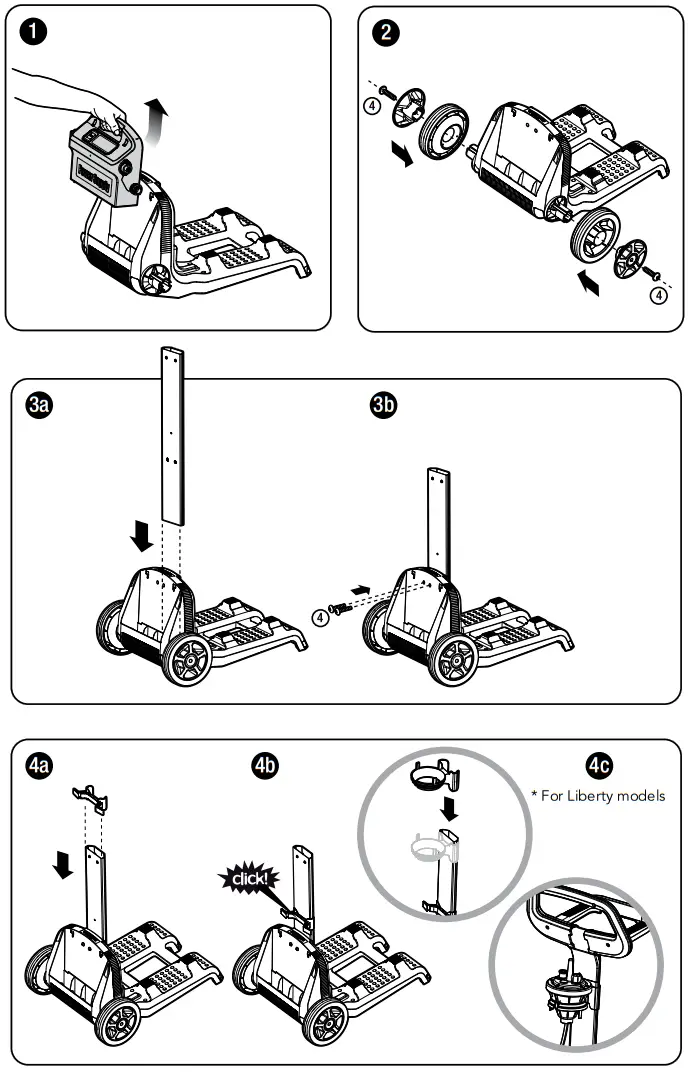
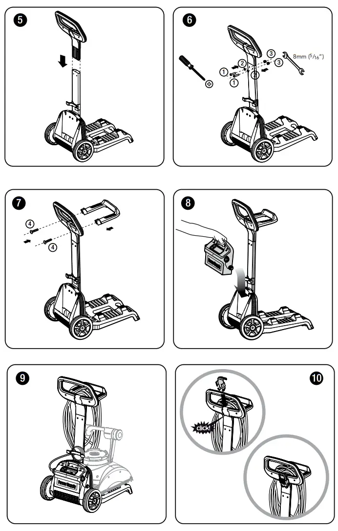
Caddy assembly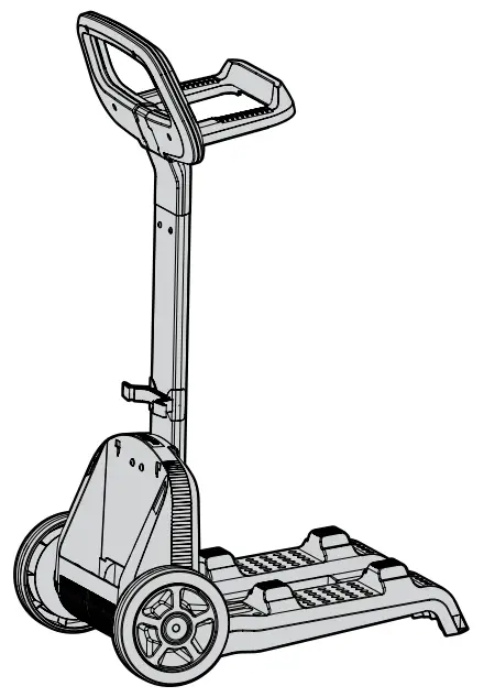
| 1 | DIN 7985 A2 M5X35 | 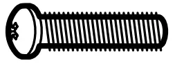 | x 2 |
| 2 | DIN 127B A2 M5 |  | x 2 |
| 3 | DIN 1587 A2 M5 |  | x 2 |
| 4 | WN 1412 A2 KA50X16 |  | x 6 |
![]()
![]() 8152240
8152240
www.maytronics.com


