![]()
EIO344 Bluetooth Mesh Adapter
Instruction Manual
Preliminary note
You will find instructions, technical data, approvals and further information using the QR code on the unit / packaging or at www.ifm.com.
1.1 Symbols used![]() Requirement
Requirement![]() Instruction
Instruction![]() Reaction, result
Reaction, result
[…] Designation of keys, buttons or indications![]() Cross-reference
Cross-reference![]() Important note
Important note
Non-compliance may result in malfunction or interference![]() Information Supplementary note
Information Supplementary note
1.2 Warnings used
| NOTE Warning of damage to property | |
| CAUTION Warning of personal injury Slight reversible injuries may result. | |
| WARNING Warning of serious personal injury Death or serious irreversible injuries may result. |
1.3 Safety symbols on the unit![]() Observe instructions in chapter ➔ Electrical connection!
Observe instructions in chapter ➔ Electrical connection!
1.4 Change history
| Version | Subject | Date |
| 0 | New creation of the document | Nov-21 |
Safety instructions
- The unit described is a subcomponent for integration into a system.
– The system architect is responsible for the safety of the system.
– The system architect undertakes to perform a risk assessment and to create documentation in accordance with legal and normative requirements to be provided to the operator and user of the system. This documentation must contain all necessary information and safety instructions for the operator, the user and, if applicable, for any service personnel authorised by the architect of the system. - Read this document before setting up the product and keep it during the entire service life.
- The product must be suitable for the corresponding applications and environmental conditions without any restrictions.
- Only use the product for its intended purpose (➔ Intended use).
- If the operating instructions or the technical data are not adhered to, personal injury and/or damage to property may occur.
- The manufacturer assumes no liability or warranty for any consequences caused by tampering with the product or incorrect use by the operator.
- Installation, electrical connection, set-up, operation and maintenance of the product must be carried out by qualified personnel authorised by the machine operator.
- Protect units and cables against damage.
- Replace damaged units, otherwise the technical data and safety will be impaired.
2.1 Cyber security
NOTE
If the unit is operated in an unprotected network environment![]() Unauthorised read or write access to data is possible.
Unauthorised read or write access to data is possible.![]() Unauthorised manipulation of the device function is possible.
Unauthorised manipulation of the device function is possible.![]() Restrict access to authorised users (e.g. password-protected access).
Restrict access to authorised users (e.g. password-protected access).![]() Assign a new password for the Bluetooth access.
Assign a new password for the Bluetooth access.
Intended use
The EIO344 communicates via IO-Link with a sensor. Using Bluetooth and an APP, the connected sensor can be read and written.
All available functions can be accessed via moneo|blue. The APP is available for Android and IOS in the App Store.
The EIO344 also features a data storage function. This allows a defective sensor to be replaced quickly.
In addition, the adapter loops through the switching or analogue output on pin 2 of the sensor; the output can still be used as a control signal.
The switching output at pin 4 of the sensor is replicated automatically or manually by the EIO344.
Several adapters can be connected to each other via the EIO404 base station. See chapter 4.3.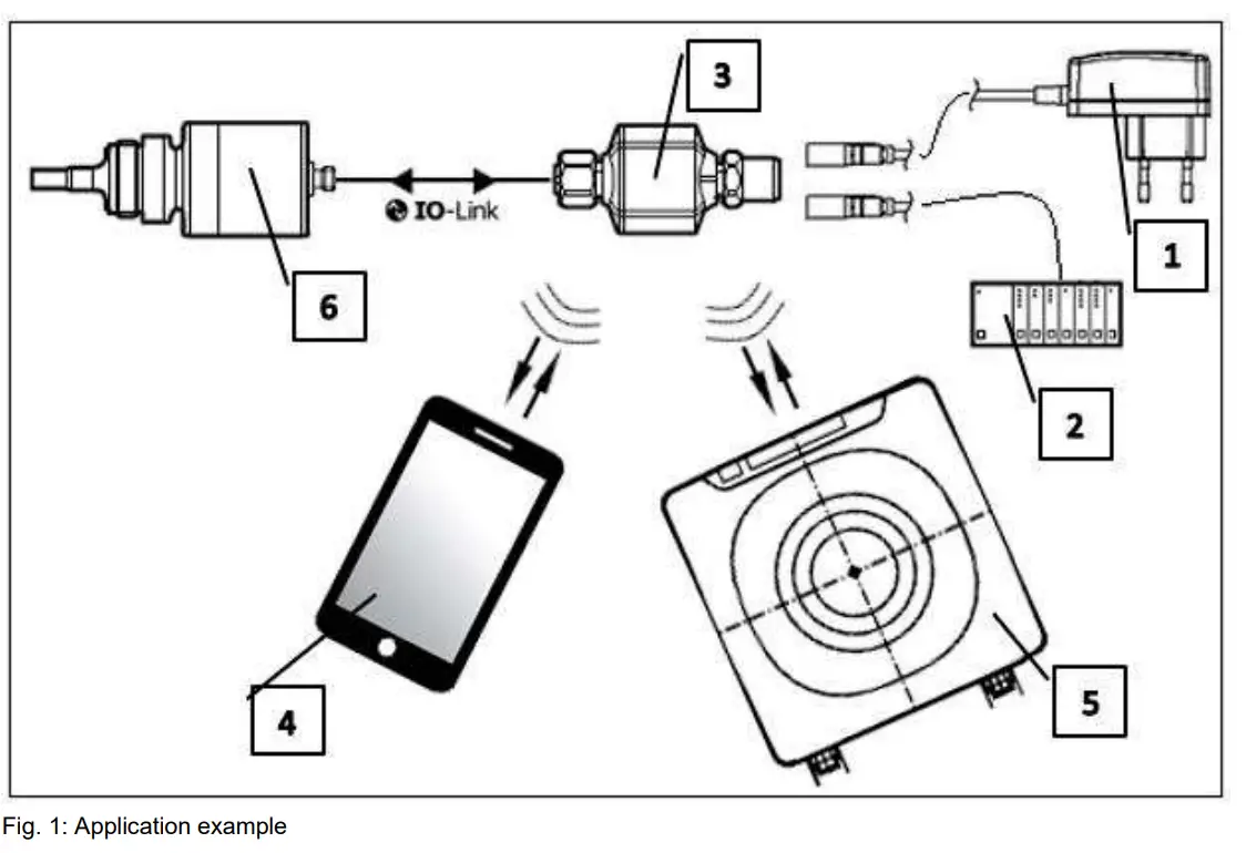
- Power supply
- PLC with voltage supply
- EIO344 adapter
- Mobile device with Bluetooth LE
- Base station EIO404 with Bluetooth Mesh
- Example sensor
![]() The unit is not suited for environments with particular requirements on mechanical stability (e.g. shock/vibration).
The unit is not suited for environments with particular requirements on mechanical stability (e.g. shock/vibration).
The unit is intended for indoor use only.
► Observe the operating conditions (➔Technical data at www.ifm.com).
The process data received via Bluetooth are used for plant monitoring
Connection possibilities
The EIO344 offers several connection options which include, among others, various functions.
4.1 IO-Link connection and outputs
This unit has two IO-Link communication interfaces.
M12 connector:
- Power supply
- Output pin 2 (looped through from sensor) and digital output pin 4
- Pin 4 for parameter setting with an IO-Link software for the device side (reset, Ou1, events, history)
M12 socket
- Input for interaction with an IO-Link device.
IO-Link is an internationally standardised IO technology (IEC 61131-9) for communicating with sensors and actuators.![]() General information about IO-Link can be found at io-link.ifm.
General information about IO-Link can be found at io-link.ifm. ![]() IO Device Description (IODD) with all parameters and process data of the unit can be found at documentation.ifm.com.
IO Device Description (IODD) with all parameters and process data of the unit can be found at documentation.ifm.com.
4.2 Bluetooth
Using a mobile device the following functions are supported:
- Parameter setting of the M12 socket to the IO-Link device
- Parameter setting of the IO-Link device
- Input for parameter setting with an IO-Link software for the device side
M12 socket:
- Input for interaction with an IO-Link device
4.3 Bluetooth Mesh
After setting up the Bluetooth Mesh, the EIO344 independently establishes the connection to a base station (EIO404). The connection can be made directly to the base station or via several EIO344 Bluetooth Mesh adapters.
Cyclical process data is transmitted to the base station at a time interval of 2-4s. With moneo on a PC or notebook, this process data can be read at the base station and the plant can be monitored.
See operating instructions EIO404 www.ifm.com.
Electrical connection
![]() The unit must be connected by a qualified electrician. Observe the national and international regulations for the installation of electrical equipment. Voltage supply according to EN 50178, SELV, PELV.
The unit must be connected by a qualified electrician. Observe the national and international regulations for the installation of electrical equipment. Voltage supply according to EN 50178, SELV, PELV.![]() CAUTION
CAUTION
Input current is not limited.![]() No fire protection.
No fire protection.![]() Protect circuits.
Protect circuits.
► Disconnect power.
► Connect the unit as follows:
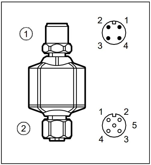 Fig. 3: Electrical connection
- 4-pole M12 connector
• Power supply
• OUT2 (white, looped through)
• OUT1 (black, replicated)
• Input for IO-Link parameter setting - 5-pole M12 socket
• Input for IO-Link signals of the sensor
| Pin | Output in operation | Input for IO-Link parameter setting |
| 1:00 | L+ -(supply voltage EIO344 + sensor) | L+ |
| 2:00 | OUT2 setting of sensor | Not used |
| 4:00 | OUT1 digital | IO-Link (parameter setting) |
| 3:00 | L- (supply voltage EIO344 + sensor) | L- |
Tab. 1: M12 connector pin assignment
| Pin | Input for IO-Link signals of the sensor |
| 1:00 | L+ (supply voltage of the sensor) |
| 2:00 | OUT2 (of the sensor) |
| 4:00 | IO-Link |
| 3:00 | L- (supply voltage of the sensor) |
| 5:00 | Not used |
Tab. 2: M12 socket pin assignment![]() The unit must not be externally supplied via the 5-pole M12 input socket (2). Pin 1, pin 2 and pin 3 are each looped through.
The unit must not be externally supplied via the 5-pole M12 input socket (2). Pin 1, pin 2 and pin 3 are each looped through.![]() Connect the sensors to the Bluetooth Mesh adapter using the connection cables provided (➔ Accessories at www.ifm.com).
Connect the sensors to the Bluetooth Mesh adapter using the connection cables provided (➔ Accessories at www.ifm.com).
5.1 Mounting the connector
To achieve the protection rating indicated in the data sheet, the following has to be observed:
► Use IO-Link cable with IP class.
► Connect the connector with the unit. The arrow indicates the position of the coding.
► Tighten the coupling nut.
- Minimum tightening torque: 0.6 Nm (tightening by hand)
- Maximum tightening torque: 1.5 Nm (using a torque wrench).
5.2 Removing the connector
► Loosen the coupling nut and simultaneously press the connector against the unit.
5.3 UL application area
For use in the USA and Canada:
► For connecting the unit and the IO-Link sensor, use UL-certified cables of category CYJV 2/7/8 having suitable ratings.
5.4 Cable length
- Maximum cable length on the input and output side (IO-Link): 20 m.
- Maximum cable length on the output side (analogue signal): no recommendation, depending on the receiver.
► Provide all input and output side cables with a strain relief approx. 200 mm behind the connectors.
Display elements, output response and troubleshooting
The indicator shows the current status of the unit with an RGB LED.
6.1 RGB indicators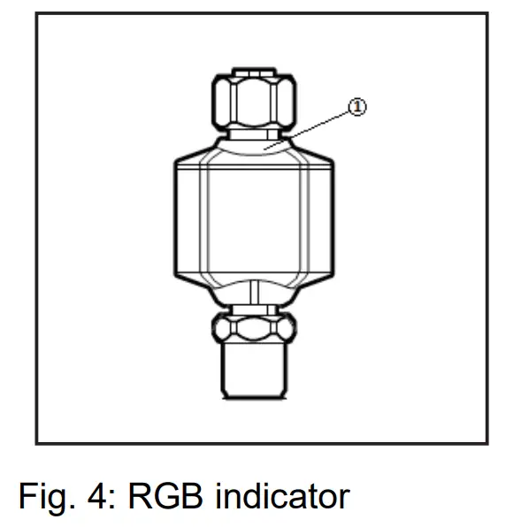
| Colour | Designation |
| Red | Interference indication |
| Green | Operation indication |
| Blue | Bluetooth |
6.2 RGB status indicator, output response and troubleshooting
The unit features self-diagnostic options. Faults are indicated by the red LED.
| Type | Description | RGB status | Output response | Troubleshooting |
| 0 | The unit works correctly | Green, on | — | — |
| 1 | 10-Link optical identification | Green, double flash | — | |
| 2 | Voltage too low | Off | Off | Check AS-i voltage supply |
| 2 | Electronics too cold | Red, 1 Hz | — | |
| 2 | Electronics too hot | Red, 1 Hz | — | |
| 2 | Faulty 10-Link device process data | Green, on | FOU | |
| 3 | Switching output short-circuited | Red, 1 Hz | Short-circuit clocking | Check wiring |
| 3 | No 10-Link device connected | Green, on | Off | Check 10-Link wiring and 10-Link sensor |
| 3 | Output configuration invalid | Red, 1 Hz | FOU | Check configuration |
| 4 | Hardware failure | Red, on | FOU | Units defective, please replace |
| — | No connection BT Mesh | Red, 1 Hz | Check the distance to the next receiver | |
| — | Bluetooth is active | Blue, on | — | |
| — | Bluetooth Mesh is active | Green, on | — | — |
| — | Device update | Green, flashing (200ms on, 800ms off) | — | Wait until the update is complete |
Tab. 4: Troubleshooting; 1: Warning, 2: Fault, 3: Note
Parameter setting
The parameters of this unit can be set via 2 interfaces. You can use IO-Link or Bluetooth to read information and make changes. Assigned information and changes are possible for each interface.
For IO-Link, connect the M12 connector to a hardware for parameter setting. The connection is established via Bluetooth with an app.![]() The parameter setting can be carried out with or without a sensor connected. Information on suitable parameter setting software at www.ifm.com.
The parameter setting can be carried out with or without a sensor connected. Information on suitable parameter setting software at www.ifm.com.
7.1 Parameter setting via IO-Link using a PC:
► Connect the Bluetooth Mesh adapter to the PC via the USB interface using the M12 connector: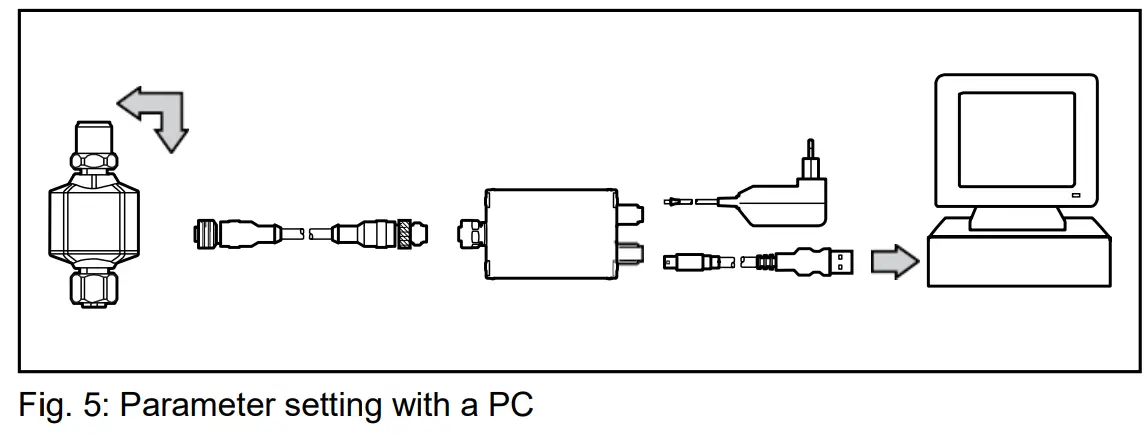 ►If the device is not detected, update the device catalogue for the parameter setting software via the internet.
► Change the parameter settings in the software.
► Transfer the parameter settings to the device.
7.2 Parameter setting by means of a mobile device via Bluetooth
► Power the Bluetooth Mesh adapter
► The Bluetooth Mesh adapter is searched for and connected via an app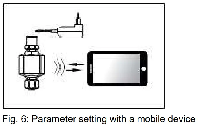
► If the device is not detected, update the device catalogue for the parameter setting software via the internet.
► Change the parameter settings in the software.
► Transfer the parameter settings to the device.
► If a sensor is connected, it can also be reached via Bluetooth.
7.3 Data storage on sensor side via M12 socket with moneo|blue
The IO-Link port offers the following optional functions:
- Storage of the IO-Link device configuration for automatic recovery (data storage)
- Device validation for connected IO-Link devices (validation ID)
- Vendor and device identification for active device validation (Vendor ID / Device ID)
Set the following parameters as requested:
| Parameter | Description | Possible values | |
| [Validation / Data Storage] | Supported 10-Link standard and behaviour of the 10-Link master when a new 10-Link device is connected to the port | No check and clear | Note: Device validation and data storage (Chapter 7.3.1) |
| Type compatible V1.0 device | |||
| Type compatible V1.1 device | |||
| Type compatible V1.1 device with Backup + Restore | |||
| Type compatible V1.1 device with Restore | |||
| [Vendor ID] | ID of the manufacturer that is to be validated | 0…65535 | Factory setting: 0 |
| [Device ID] | ID of the 10-Link device that is to be validated | 0…16777215 | Factory setting: 0 |
If the parameter values [Vendor ID] or [Device ID] are changed in the online mode, the data memory will be deleted and a new backup of the parameter values of the connected IO-Link device will be created in the IO-Link master.
► Save changed values on the device.
7.3.1 Note: Device validation and data storage
The user can choose how the IO-Link ports are to behave with regard to the device validation and the storage / recovery of parameter data of the connected IO-Link device.
The following options are available:
| Option | Validation of the 10- Link device | Storage of the parameter values | Recovery of the parameter values |
| [No check and clear] | no | no | no |
| [Type compatible V1.0 device] | yes, check the compatibility with 10-Link standard V1.0 | no | no |
| [Type compatible V1.1 device] | yes, check the compatibility with 10-Link standard V1.1 | no | no |
| [Type compatible V1.1 device with Backup + Restore] | yes, check the compatibility with 10-Link standard V1.1 and uniformity of construction (vendor ID and device ID) | yes, automatic storage of the parameter values; changes of the current parameter values will be stored | yes, recovery of the parameter values when connecting an identical 10-Link device with factory settings |
| [Type compatible V1.1 device with Restore] | yes, check the compatibility with 10-Link standard V1.1 and uniformity of construction (vendor ID and device ID) | no, there is no automatic storage; changes of the current parameter values will not be stored | yes, recovery of the parameter values when connecting an identical 10-Link device with factory settings |
8 Parameters and commands
8.1 Parameters and commands via IO-Link
| Parameter | Function |
| Application-specific identifier | Possibility to identify a device with user or application-specific information |
| Plant identification identifier | Possibility to identify a device with function-specific information |
| Location identifier | Possibility to identify a device with location-specific information |
| Event counter | The event counter increments when the assigned event has occurred |
| Event history | Displays a list of the last occurred events |
| Operating hours | Operating hours counter since delivery |
| Internal temperature | Current internal temperature |
| Active events | Current upcoming events |
| Parameter configuration faults | Shows the parameter incorrectly set at the time of the download |
| FOU | Behaviour of output 2 in case of an internal fault |
| Output configuration | Setting the output behaviour |
| Switching bit | Bit in the 10-Link process data stream that is to be output as switch point 1 |
Tab. 3: IO-Link parameters
| Commands | Function |
| Reset application | Resets settings (except: application-specific identifier, plant identifier, location identifier, Bluetooth password, Bluetooth Mesh network) |
| Back to box | All settings are set to the factory setting and communication is blocked until the next switch-off and switch-on |
| Reset event history | Resets the event history |
| Reset event counter | Resets the event counter |
| Reset Bluetooth password | Resets the Bluetooth password |
| Flash on | Activating the command makes the responding unit flash |
| Flash off | Deactivates the flashing of the LED of the previously addressed unit |
| System test command 240 | Test event 1 8DFE is activated |
| System test command 241 | Test event 1 8DFE is deactivated |
| System test command 242 | Test event 2 8DFF is activated |
| System test command 243 | Test event 2 8DFF is deactivated |
8.2 Bluetooth parameters and commands
| Parameter | Function |
| Name of the manufacturer | Manufacturer name assigned a manufacturer ID |
| Manufacturer text | Additional information about the manufacturer |
| Product name | Full product name |
| Product ID | Manufacturer-specific product or type identification (e.g. article or order number) |
| Product text | Additional product information about the device |
| Serial number | Unique, manufacturer-specific identification of the individual unit |
| Hardware version | Unique, manufacturer-specific identification of the hardware version of the individual device |
| Firmware version | Unique, manufacturer-specific identification of the firmware version of the individual device |
| Bootloader version | Unique, manufacturer-specific identification of the bootloader version of the individual device |
| EEPROM version | Manufacturer-specific EEPROM version |
| Bluetooth MAC address | MAC address of the Bluetooth interface |
| Bluetooth software version | Unique, manufacturer-specific identification of the Bluetooth software version of the individual device |
| Bluetooth bootloader version | Unique, manufacturer-specific identification of the Bluetooth bootloader version of the individual device |
| Operating hours | Operating hours counter since delivery |
| Internal temperature | Current internal temperature |
| Active events | Current upcoming events |
| Device status | Display of the current device and diagnostic status |
| Application number | Unique ID of the adapter in the mesh network |
| FOU | Behaviour of output 2 in case of an internal fault |
| Output configuration | Setting the output behaviour |
| Switching bit | Bit in the IO-Link process data stream that is to be output as switch point 1 |
| P-n | Transistor function, switching logic of the outputs (pnp/npn) |
| Security mode | Activate or deactivate Bluetooth security |
| Bluetooth password | Code for write protection |
| Device name | Designation of the adapter |
| Base station name | Name of the connected base station |
| Transmission interval | Transmission interval of process data via mesh |
| Signal strength | Signal strength of the mesh network |
| BT mesh transmission | BT password function |
| BT Mesh ID | Assigned Bluetooth Mesh ID |
| BT Mesh address | Bluetooth Mesh address |
| BT Mesh node | Bluetooth Mesh support |
| BT firmware version | Version of the installed Bluetooth firmware |
| BT firmware type | Type of Bluetooth software |
| BT firmware data block | Bluetooth packet size of the update data block |
| BT firmware maximum size | Bluetooth maximum packet size |
| Master cycle time | Current cycle time to the connected IO-Link device |
| Set master cycle time | Pre-configuration of the IO-Link master cycle time |
| Event of the master port | Event of the IO-Link master port |
| Settings of the master port | Settings of the IO-Link master |
| Com speed of the master port | IO-Link Com rate of the connected IO-Link sensor |
| Validation and data storage mode of the master port | Configuration of the data storage mode |
| Manufacturer ID of the master port | Manufacturer ID of the pre-configured data storage device |
| Device ID of the master port | Device ID of the pre-configured data storage device |
| Manufacturer ID of the IO-Link device | Manufacturer ID of the connected IO-Link device |
| Device ID of the IO-Link device | Device ID of the connected IO-Link device |
| Application-specific identifier of the IO- Link device | Possibility to identify a device with user or application specific information |
| PDin IO-Link device | Process data input of the connected device |
| Product name IO-Link device | Product name of the connected device |
| Serial number IO-Link device | Serial number of the connected device |
| PDout IO-Link device | Process data output of the connected device |
| IO-Link device status | Device status of the connected device |
| Event IO-Link device | Event of the connected device |
Tab. 5: Bluetooth parameters
| Commands | Function |
| Reset application | Resets settings (except: application-specific identifier, plant identifier, location identifier, Bluetooth password, Bluetooth Mesh network) |
| Back to box | All settings are set to the factory setting and communication is blocked until the next switch-off and switch-on |
| Reboot | Reboots the device |
| Signal | Flashing on and off, makes an LED flash on the device |
| Stream set | Reading the Bluetooth firmware |
| Start stream set | Start reading the Bluetooth firmware |
| Getcrc | Bluetooth firmware update |
| Install | Installs the downloaded file |
| Preinstall | Prepares the device for the update |
| Data storage | Triggers the data storage of the connected IO-Link device |
| Read request | Read request of the acyclic data |
| Write request | Write request of the acyclic data |
Tab. 6: Bluetooth commands
Set-up of the moneo configure application
9.1 Function moneo configure
With moneo configure, the adapter can be accessed via the IO-Link interface. This interface allows few functions.
9.2 System requirements
moneo configure is installed on a Windows operating system.
- Windows 7/10/11
- USB interface
A ready-made system for this purpose is also offered by ifm.
9.3 Installation of moneo configure
► Open the installation file
► Follow the installation instructions![]() Update the IODD catalogue when using the moneo configure for the first time.
Update the IODD catalogue when using the moneo configure for the first time.
9.4 Connection with a PC
► Connect PC/laptop with a USB interface
► Connect the EIO344 to the USB interface
► Start the moneo software
► Search for participant and connect![]() Information on moneo configure can be found in the software or in the manual.
Information on moneo configure can be found in the software or in the manual.
Set-up of the moneo|blue application
10.1 moneo|blue’s functions
With moneo|blue, the EIO344 transmits live data, which is displayed and allows the parameters to be set. Saved data can be read via a data file.
Acyclic parameters and cyclic process data can be read and written.
10.2 System requirements
To install moneo|blue on a mobile device such as smartphone or tablet an internet connection is recommended. moneo|blue can be downloaded from the “Apple APP Store” or “Google Play Store”. The mobile device must meet the following system requirements:
- Bluetooth 4.0
- iOS operating system version 8.0 or higher
- Android operating system version 4.3 or higher
10.3 Installation of moneo|blue
► Open the Apple APP Store or the Google Play Store
► Search for moneo|blue
► Follow the installation instructions![]() Update the IODD catalogue when using the moneo|blue App for the first time.
Update the IODD catalogue when using the moneo|blue App for the first time.![]()


10.4 Connect a mobile device
► Activate Bluetooth data transmission on the mobile device
► Position the mobile device within the range of EIO344
► Select the requested EIO344
► Enter the access password 0000![]() You can find information about moneo|blue in the App description.
You can find information about moneo|blue in the App description.
11 Copyright and trademarks
All trademarks and company names used are subject to the copyright of the respective companies
Apple® is a registered trademark of Apple Inc.
Google® is a registered trademark of Google LLC.
Bluetooth® is a registered trademark of Bluetooth SIG Inc.
iOS® operating system is a registered trademark of Apple Inc. Android® operating system is a registered trademark of Google LLC.
Approvals and certificates
The EU declaration of conformity, approvals and country-specific certificates are available at: www.ifm.com
Approval-related notes: → Packing slip
Maintenance, repair and disposal
The unit is maintenance-free.
► After use dispose of the device in an environmentally friendly way in accordance with the applicable national regulations. Cleaning the device:
► Disconnect the device from the voltage supply.
► Clean the device from dirt using a soft, chemically untreated and dry micro-fibre cloth.

Bluetooth Zulassung
El0344
El0404
Great Britain
Read the operating instructions before set-up and keep them for the duration of use.
- urn electronic gmbh hereby declares that the devices E10344 and E10404 are in compliance with the relevant statutory requirements.
- The full text of the Declaration of Conformity, technical data,instructions, approvals, contacts and further information is available at: documentationifm.com.
WARNING! The operation of this device can cause radio interference in residential areas.
- The device has the following operating frequencies and transmitter powers:
| Radio technology | Frequency bands | Max. transmitter po-wer |
| Bluetooth | 2.4 GHz | 10 dBm |
- Due to radio frequency exposure limits this device should be installed and operated with a minimum distance of 20 cm between the device and the body of the user or nearby persons.
- The device emits radio waves that may interfere with the operation of electronic devices in the vicinity, including pacemakers, hearing aids and defibrillators. If you have a pacemaker or other implanted medical device, do not use the sensor without first consulting your doctor or the manufacturer of your medical device. Keep a safe distance between the device and your medical products and refrain from further use of the device if you observe permanent impairment of your medical devices.
USA
Only valid for: E10344, E10404
FCC information:
Suppliers Declaration of Conformity
Models: E10344, E10404
U.S. Responsible Party ifm elector inc.
1100 Atwater Drive / Malvem, PA 19355. Phone: +1 800 441 8246 This device complies with Part 15 of the FCC Rules. Operation is subject to the following two conditions:
- This device must not cause harmful interference, and
- This device must accept any interference received, including interference that may cause undesired operation.
Changes or modifications to this device that have not been expressly approved by ifm could void the user’s authority to operate the equipment.
Note: This equipment has been tested and found to comply with the limits for a Class B digital device. pursuant to part 15 of the FCC Rules. These limits are designed to provide reasonable protection against harmful interference in a residential installation. This equipment generates. uses and can radiate radio frequency energy and, if not installed and used in accordance with the instructions. may cause harmful interference to radio communications. However. there is no guarantee that interference will not occur in a particular installation. If this equipment does cause harmful interference to radio or television reception, which can be determined by turning the equipment off and on. the user is encouraged to try to correct the interference by one or more of the following measures:
- Reorient or relocate the receiving antenna.
- Increase the separation between the equipment and receiver.
- Connect the equipment into an outlet on a circuit different from that to which the receiver is connected.
- Consult the dealer or an experienced radio/TV technician for help.
RF Exposure Info
Due to radio frequency exposure limits this device should be installed and operated with a minimum distance of 20 cm between the device and the body of the user or nearby persons. The measurement results comply with the FCC limit per 47 CFR §2.1091 for the uncontrolled RF Exposure of mobile devices.
Canada
Only valid for: E10344, E10404
ISED note: This device contains licence-exempt transmitters/receivers that comply with Innovation. Science and Economic Development Canada’s licence-exempt RSSs. Operation is subject to the following two conditions:
- This device may not cause interference.
- This device must accept any interference, including interference that may cause undesired operation of the device.
This device complies with ISED RSS-102 radiation exposure limits set forth for an uncontrolled environment when the device is installed and operated with a minimum separation distance of 20 cm between the device and any human body.![]()


