![]()
WiFi 5in 1 Smart LED Controller Instruction Manual
GL-W-CM-1-002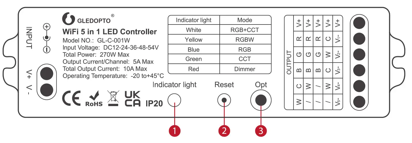
GL-W-CM-I-002 WiFi 5in 1 Smart LED Controller
- LED indicator Different color indicators correspond to different functions.
- Reset Short press once to switch frequency; Long press 2s for system reset.
- OPT Short press to switch modes; Long press to memorize if the light is under OFF status or not.
Note: Short press the “OPT” key once (when switching the functions), the device will be disconnected to the network, and you will need to search lights again.
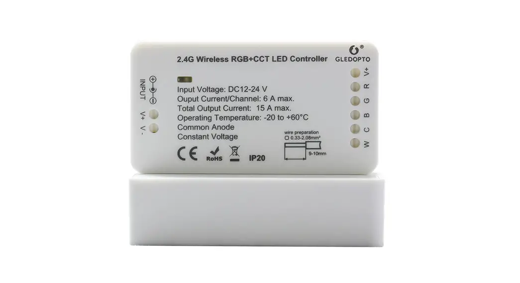
SPECIFICATION
| Product Name | WiFi 5 in 1 LED Controller |
| Model NO. | GL-C-001W |
| Size | 125x37x24mm |
| Input Voltage | DC12-24-36-48-54V |
| Protection Rate | IP20 |
| Total Power | 270W |
| Output Current/Channel | 5A Max |
| Total Output Current | 10A Max |
| Operating Temperature | -20- 45°C |
| Common Anode | |
| Constant Voltage | |
FUNCTIONS OF DIFFERENT INDICATOR COLORS SHOWN AS FOLLOWING TABLE:
| RGBCCT | RGBW | RGB | CCT | Dimmer | |
| Indicator Color |
NETWORK PAIRING:
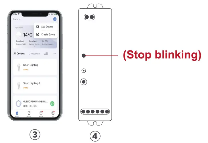
1. Pairing with your phone Add the device to the WiFi network
- Please ensure the device wasn’t be paired. Otherwise, please “RESET” the device according to the part II “RESET”.
- After STEP 1, there will be a pairing process about 90s. The indicator light will blink slowly
- Open the tuya APP add the device.
- If the pairing done successfully after the above steps, the indicator light stops flashing and the strip turns green (cool white).

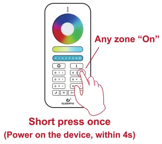
2. Pairing with 2.4GHz RF Remote Control / Touch Panel
- The pairing will be timeout after 4 seconds when the device powered on.
- The pairing will be done successfully by pressing any zone “On” key of the 2.4G RF Remote or touch panel.
- The light strip will blink 3 times.
RESET:
1. RESET the WiFi Network O Methodl : Delete the device on the APP, after a period of time(a few seconds to a dozen seconds, depending on the network status), the indicator starts flashing.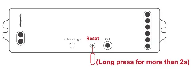
- Method2: Long press for more than 2s to reset to unpair the network.
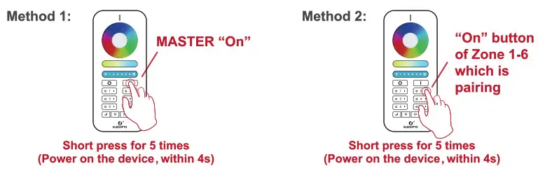
RESET the 2.4GHz RF Network 0 Method 1: Short press the Master “On” key 5 times within 4 seconds after the device powered on, the device will blink 6 times. - Method 2: Short press continuously 5 times the Zone “On” key the device being paired within 4 seconds after the device powered on, the device will blink 6 times.
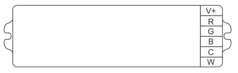
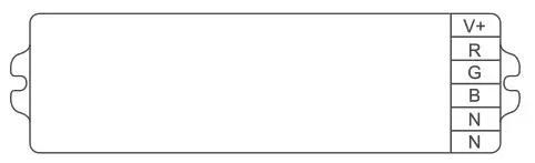
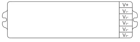
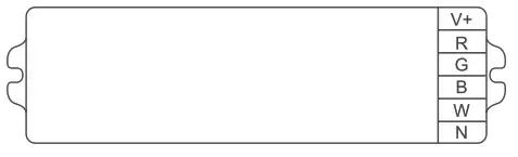
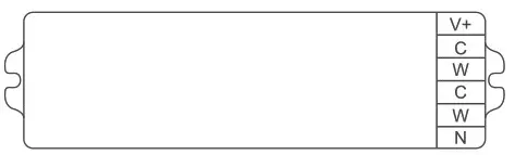
WIRING DIAGRAM:
- RGBCCT: Under RGBCCT function, the RGBCCT strip can be connected to the device.

- RGBW: Under RGBW function, the RGBW strip can be connected, without any connection to “N” terminal.

- RGB: Under RGB function, the RGB strip can be connected, without any connection to “N” terminal.

- CCT: Under CCT function, two pieces of CCT strips can be connected, without any connection to “N” terminal.

- DIMMER: Under dimmer function, five pieces of single color strips can be connected.

2. Frequency Settings In order to be applicable to different power supplies, the frequency of device is selectable as 600Hz. 800Hz, 1000Hz. 2000Hz. 4000Hz. 8000Hz with default frequency 1000HZ. Once short pressing “Reset” key, the frequency will switch into the next one. The indicator will flash in Pink color and resume to previous color. The rule of indicator flashing times for different frequency please refer to table.
POWER-ON STATUS & FREQUENCY SETTINGS
1. Power-on Status Settings Long press the ‘opt’ key for 2S , the light strip flashes for 2 times , the device will remember the on-off state before the last power failure and return to the previous state when powered on . Repeat the operation again to cancel this function , the device will be on by default when powered on.
1000Hz -> 2000Hz -> 4000Hz -> 8000Hz -> 600Hz ->800Hz -> 1000Hz
| 600Hz | 800Hz | 1000Hz | 2000Hz | 4000Hz | 8000Hz | |
| Flashing times | 1 | 2 | 3 | 4 | 5 | 6 |
![]() Attention
Attention
- Please check whether the input voltage of the constant voltage power supply is in accordance with the controller, and please check the connection of both the cathode andanode.
- The working Voltage is DC12-24-36-48-54V, the controller will be broken if the voltage Is higher than 54V.
- Non-professional user cannot dismantle the controller directly, otherwise, it may cause fire and electric shock.
- The working temperature is -20-45°C; Do not use the device to direct sunlight, moist and other high temperature area.
- Please do not use controller around the mental area and high magnetic field, otherwise, It will badly affect the control distance.
DISCLAIMERS
- This manual may contain inaccuracies or discrepancies of the product operations, or typographical errors. Our company will update the contents of this manual according to the improvements and changes of product functions, and regularly improve and update the software and hardware of products described in this manual. The updates will be shown in the latest edition of this manual without further notice.
- Due to the continuous adoption of new technologies by our company, the product parameters will be changed without any notice in prior.
- This manual is only for reference and guidance for customers. It does not guarantee that it is completely consistent with the actual product. The actual application is subject to the actual product.
- The parts, components and accessories mentioned in this manual do not represent the standard configuration of the product. The detailed configu-ration is subject to the packing list.
- All texts, tables and pictures in this manual are protected by the relevant national laws, and may not be used without permission by supplier.
- The copyright and right of the final interpretation of this manual are reserved by our company.
WiFi Smart LED Controller User instruction
![]()
LED-Trading Tobias Ebert Schoeneicher Str. 42, Schoeneiche b. Berlin, Germany, 15566 0049 30 641 689 17 [email protected]


