MarCom GW-IMP-WEB-4 Web Counter Datalogger
Revision Table
| Release No. | Date | Revision Description |
| Rev. 1 | 11/04/19 | Nuovo formato guida |
| Rev. 1.1 | 28/06/19 | Modificata sezione FTP setup. Aggiunta sezione guida download file FTP. |
| Rev. 1.2 | 13/01/2020 | From GW-IMP-WEB-4 v1.8 |
Manual downloadable at:
https://shop.marcomweb.it/en/shop-online/remote-control/datalogger/gw-imp-web-4-pulse-counter-web-datalogger-18-di-eth-l-dettagli.html
GENERAL INFORMATION
System
The web pulse counter datalogger is able to count pulses on the digital inputs (2 expandable by default). Via the web interface it is possible to display counting values, change pulse weight and enter an offset in case of misalignment or post installation of the counter. All data can be displayed via the web interface or accessed via MODBUS TCP connection (on request also via MODBUS RTU). As an optional feature, the data logger can be ordered with time-based saving of the counters to a csv file in the internal memory or to an SD card. The files can be downloaded via ftp server functionality.
This version of the datalogger has a maximum of 18 countable inputs and provides the values on:
- RS232 MODBUS RTU slave port;
- RS485 MODBUS RTU slave port;
- Ethernet MODBUS TCP Server port (max 3 client connection);
Features
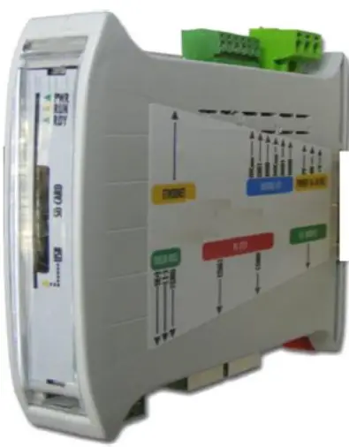
Connections
The gateway has:
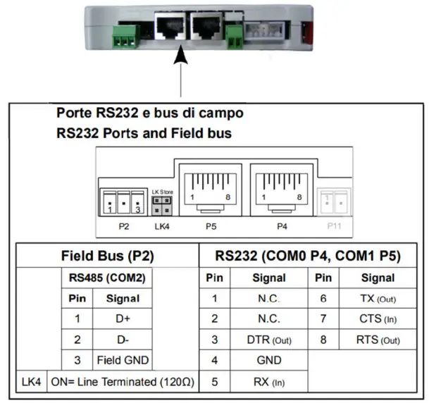
- -2 x RS232 serial port for reading data from a Modbus RTU master
- 1 x RS485 serial port for reading data from a Modbus RTU master, identified by the word FIELDBUS
- 1 x Ethernet port for reading data from a Modbus TCP master
- SD card slot for saving data
- 1 x screw connector for power supply 10-30 VDC (min. 2 W)
- LED indicators on the front for communication diagnostics
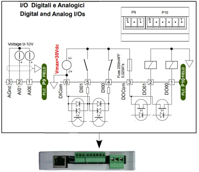
- 2+16 x Digital Input (*)
- 2+8 x Digital Output (*)
(*) Their status is mapped in Modbus registers.
I/O Connections
Serial connections
RS232 and RS485 serial connection (FIELD BUS):
CONFIGURATION AND MODBUS MAP
TCP Connection
In order to view the web pages containing the data, it is necessary to connect the datalogger to the Ethernet network via the RJ45 port available. Using a web browser, simply type in the default address: 192.168.0.122; if there is no connection, check that your network card has an address on the 192.168.0.X subnet.
This will take you to the main datalogger screen with the counter values..
Web Pages
Home datalogger
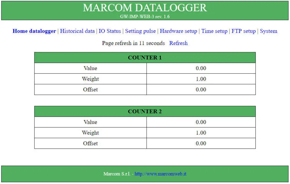
From this page, through the links at the top of the page, the following pages can be accessed:
- Historical data; Page containing the last 5 datalogger values and setting the save time.
- IO Status; Page to check the status of the inputs and to set the outputs available to the datalogger.
- Setting pulse; Page for setting pulse counter parameters such as pulse weight and count offset.
- Hardware setup; Page to change the hardware parameters of the pulse counter such as IP address and Modbus communication parameters.
- Time setup; Page to change the time or activate the NTP protocol.
- FTP Setup; Page to configure the automatic sending of files to an FTP server.
- System; Page for logging in to enable changes and to reboot the system.
Historical data
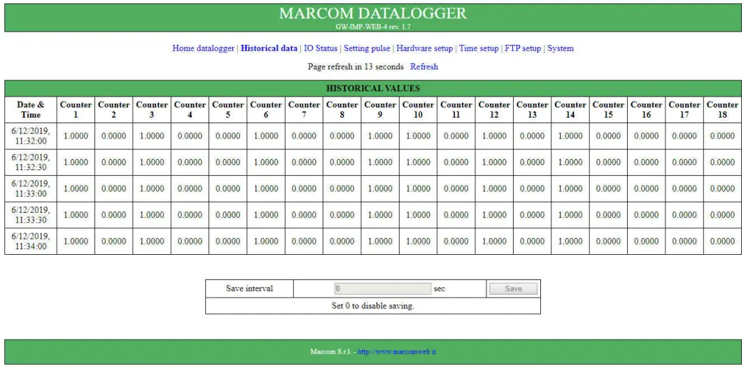
Data is stored at fixed intervals, set in the Save interval field. This value must be between 30 seconds and 86400 seconds (corresponding to one day) and indicates every how many seconds the data is stored starting at 00:00 on the first day of the month. If the Save interval value is set to 0, saving is disabled.
IO Status
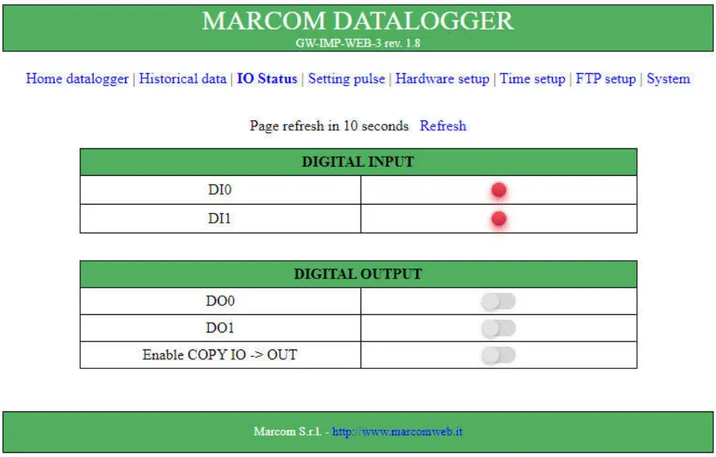
On the IO Status page you can check the status of the digital inputs, view and set (after login) the status of the digital outputs and the percentage value of the analogue inputs..
Setting pulse
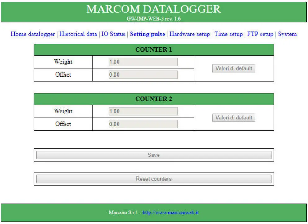
On the Setting datalogger page, it is possible to reset counter values, change pulse weights and offsets.
Hardware setup
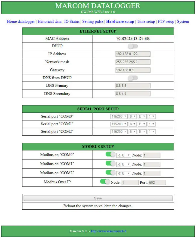
- The parameters that can be changed in the Hardware Setup page depend on the version of the counter.
- The RS232 serial port corresponds to COM0, while the RS485 serial port corresponds to COM2.
- After changing and saving the parameters, the device must be restarted.
- This can also be done from the System page.
Time setup
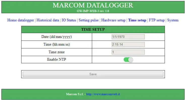
In the Time setup page it is possible to change the device time and enable the update from NTP server.
The device does not have a realtime clock, so if the NTP update is not enabled, each time the device is restarted it resets to zero time (1/1/1970 00:00:00).
FTP setup
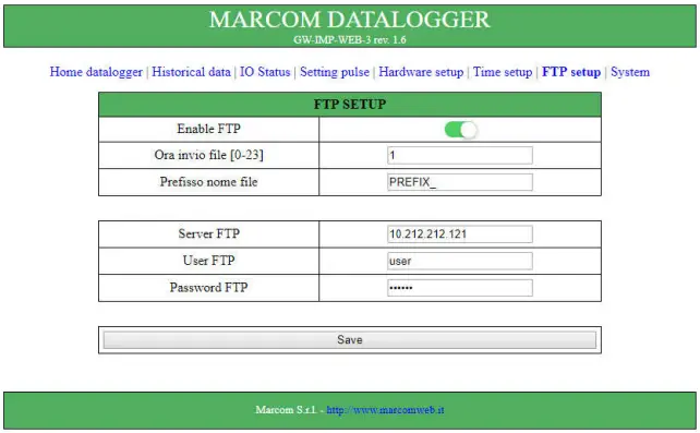
The fields User FTP and Password FTP must be filled in, otherwise the file will not be sent successfully.
If the FTP server sending is enabled, a new file is created every day at the indicated time, with the saves of the last 24 hours. This file is saved in the SD memory. Every day at the indicated time the datalogger tries to send the file to the FTP server adding to the name the prefix set, if the sending is not successful the datalogger tries again the next day.
System
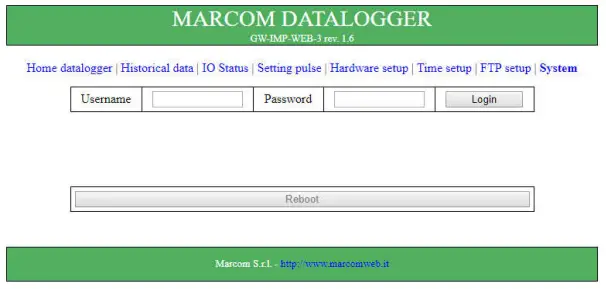
On this page it is possible to login (Username = Admin, Password = Admin), which is necessary to modify the parameters, and to force a restart of the device..
Modbus area map
The data read from the counter are placed in the Holding Register memory area. A copy of the values in the following table is present from register 4×20000.
Modbus addresses are base 1 and double word values may need to be swapped.
| Variabile Name | Type | MODBUS Address | Note |
| DIGITAL INPUT 1 | UINT | 4×40001 | Digital Input (0= contact opened, 1=contact closed ) |
| DIGITAL INPUT 2 | UINT | 4×40002 | |
| DIGITAL INPUT 3 | UINT | 4×40003 | |
| DIGITAL INPUT 4 | UINT | 4×40004 | |
| DIGITAL INPUT 5 | UINT | 4×40005 | |
| DIGITAL INPUT 6 | UINT | 4×40006 | |
| DIGITAL INPUT 7 | UINT | 4×40007 | |
| DIGITAL INPUT 8 | UINT | 4×40008 | |
| DIGITAL INPUT 9 | UINT | 4×40009 | |
| DIGITAL INPUT 10 | UINT | 4×40010 | |
| DIGITAL INPUT 11 | UINT | 4×40011 | |
| DIGITAL INPUT 12 | UINT | 4×40012 | |
| DIGITAL INPUT 13 | UINT | 4×40013 | |
| DIGITAL INPUT 14 | UINT | 4×40014 | |
| DIGITAL INPUT 15 | UINT | 4×40015 | |
| DIGITAL INPUT 16 | UINT | 4×40016 | |
| DIGITAL INPUT 17 | UINT | 4×40017 | |
| DIGITAL INPUT 18 | UINT | 4×40018 | |
| DIGITAL OUTPUT 1 | UINT | 4×41500 | Digital Output (0= contact opened, 1=contact closed ) |
| DIGITAL OUTPUT 2 | UINT | 4×41501 | |
| DIGITAL OUTPUT 3 | UINT | 4×41502 | |
| DIGITAL OUTPUT 4 | UINT | 4×41503 | |
| DIGITAL OUTPUT 5 | UINT | 4×41504 | |
| DIGITAL OUTPUT 6 | UINT | 4×41505 | |
| DIGITAL OUTPUT 7 | UINT | 4×41506 | |
| DIGITAL OUTPUT 8 | UINT | 4×41507 | |
| DIGITAL OUTPUT 9 | UINT | 4×41508 | |
| DIGITAL OUTPUT 10 | UINT | 4×41509 | |
| RESET | UINT | 4×40000 | Reset of actual counters |
| CONTATORE 1 | REAL | 4×41024 | Counter total |
| CONTATORE 2 | REAL | 4×41026 |
| CONTATORE 3 | REAL | 4×41028 | |
| CONTATORE 4 | REAL | 4×41030 | |
| CONTATORE 5 | REAL | 4×41032 | |
| CONTATORE 6 | REAL | 4×41034 | |
| CONTATORE 7 | REAL | 4×41036 | |
| CONTATORE 8 | REAL | 4×41038 | |
| CONTATORE 9 | REAL | 4×41040 | |
| CONTATORE 10 | REAL | 4×41042 | |
| CONTATORE 11 | REAL | 4×41044 | |
| CONTATORE 12 | REAL | 4×41046 | |
| CONTATORE 13 | REAL | 4×41048 | |
| CONTATORE 14 | REAL | 4×41050 | |
| CONTATORE 15 | REAL | 4×41052 | |
| CONTATORE 16 | REAL | 4×41054 | |
| CONTATORE 17 | REAL | 4×41056 | |
| CONTATORE 18 | REAL | 4×41058 | |
| PESO_IMP_1 | REAL | 4×41074 | Weight assigned for pulses on the respective counter 1 |
| PESO_IMP_2 | REAL | 4×41076 | |
| PESO_IMP_3 | REAL | 4×41078 | |
| PESO_IMP_4 | REAL | 4×41080 | |
| PESO_IMP_5 | REAL | 4×41082 | |
| PESO_IMP_6 | REAL | 4×41084 | |
| PESO_IMP_7 | REAL | 4×41086 | |
| PESO_IMP_8 | REAL | 4×41088 | |
| PESO_IMP_9 | REAL | 4×41090 | |
| PESO_IMP_10 | REAL | 4×41092 | |
| PESO_IMP_11 | REAL | 4×41094 | |
| PESO_IMP_12 | REAL | 4×41096 | |
| PESO_IMP_13 | REAL | 4×41098 | |
| PESO_IMP_14 | REAL | 4×41100 | |
| PESO_IMP_15 | REAL | 4×41102 | |
| PESO_IMP_16 | REAL | 4×41104 | |
| PESO_IMP_17 | REAL | 4×41106 | |
| PESO_IMP_18 | REAL | 4×41108 | |
| OFFSET_1 | REAL | 4×41124 | Offset added to total |
| OFFSET_2 | REAL | 4×41126 | |
| OFFSET_3 | REAL | 4×41128 | |
| OFFSET_4 | REAL | 4×41130 | |
| OFFSET_5 | REAL | 4×41132 | |
| OFFSET_6 | REAL | 4×41134 | |
| OFFSET_7 | REAL | 4×41136 |
| OFFSET_8 | REAL | 4×41138 | |
| OFFSET_9 | REAL | 4×41140 | |
| OFFSET_10 | REAL | 4×41142 | |
| OFFSET_11 | REAL | 4×41144 | |
| OFFSET_12 | REAL | 4×41146 | |
| OFFSET_13 | REAL | 4×41148 | |
| OFFSET_14 | REAL | 4×41150 | |
| OFFSET_15 | REAL | 4×41152 | |
| OFFSET_16 | REAL | 4×41154 | |
| OFFSET_17 | REAL | 4×41156 | |
| OFFSET_18 | REAL | 4×41158 | |
| NUMERO IMPULSI 1 | UDINT | 4×41174 | Total number of pulses |
| NUMERO IMPULSI 2 | UDINT | 4×41176 | |
| NUMERO IMPULSI 3 | UDINT | 4×41178 | |
| NUMERO IMPULSI 4 | UDINT | 4×41180 | |
| NUMERO IMPULSI 5 | UDINT | 4×41182 | |
| NUMERO IMPULSI 6 | UDINT | 4×41184 | |
| NUMERO IMPULSI 7 | UDINT | 4×41186 | |
| NUMERO IMPULSI 8 | UDINT | 4×41188 | |
| NUMERO IMPULSI 9 | UDINT | 4×41190 | |
| NUMERO IMPULSI 10 | UDINT | 4×41182 | |
| NUMERO IMPULSI 11 | UDINT | 4×41194 | |
| NUMERO IMPULSI 12 | UDINT | 4×41196 | |
| NUMERO IMPULSI 13 | UDINT | 4×41198 | |
| NUMERO IMPULSI 14 | UDINT | 4×41200 | |
| NUMERO IMPULSI 15 | UDINT | 4×41202 | |
| NUMERO IMPULSI 16 | UDINT | 4×41204 | |
| NUMERO IMPULSI 17 | UDINT | 4×41206 | |
| NUMERO IMPULSI 18 | UDINT | 4×41208 |
GUIDE TO DOWNLOADING FILES FROM SD
The following section contains instructions for FTP connection to the datalogger to download files or delete older files already transferred to the FTP server..
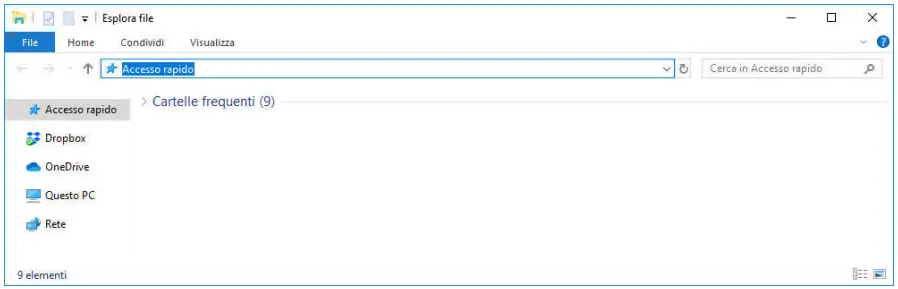
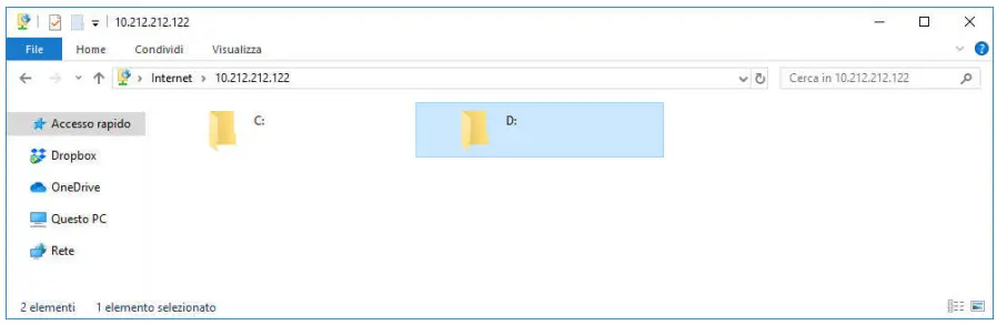
File Explorer
- Open a new File Explorer window

- In the address bar, type ftp://Admin:[email protected] and pusch Enter

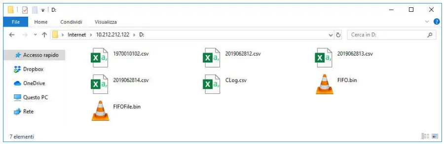
- Access the D folder

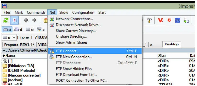
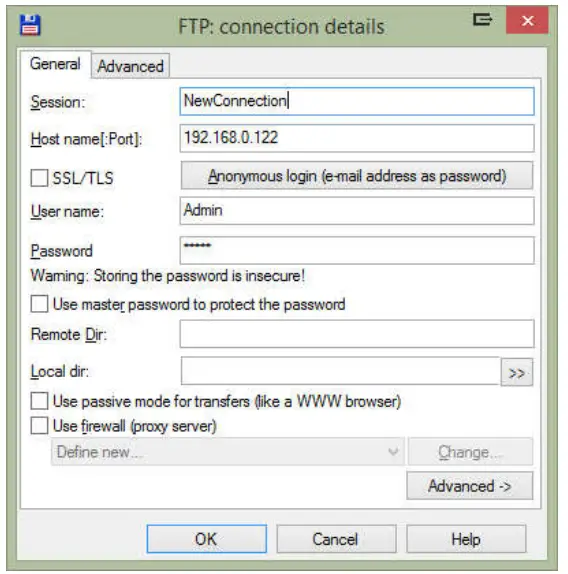
Total Commander
- Open FTP Connect…

- Create a new connection; Username = Admin, Password = Admin

- In the “Connect to ftp server” window, click on Connect and after connecting, access the folder [D:].
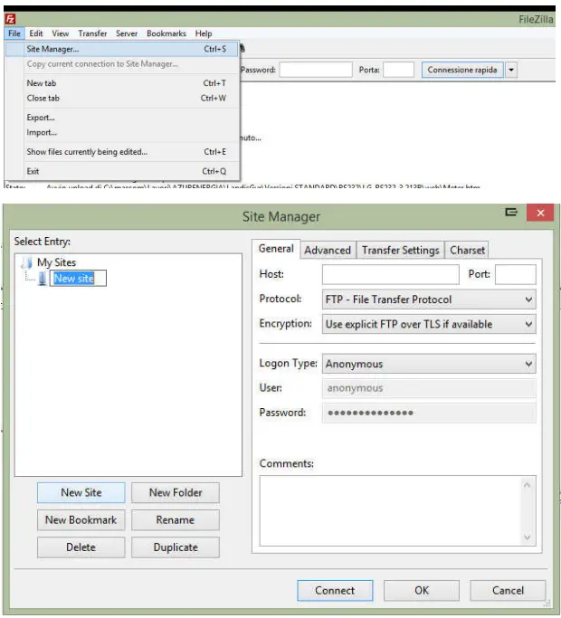
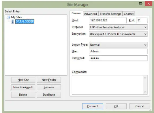
FileZilla
- Open Site Manager and create a new site.

- Enter the IP address (Default 192.168.0.122) in the Host field, the connection port (Default 21) in the Port field, set Logon Type to Normal, User is Admin and Password is Admin

- Connect the server and access the D:
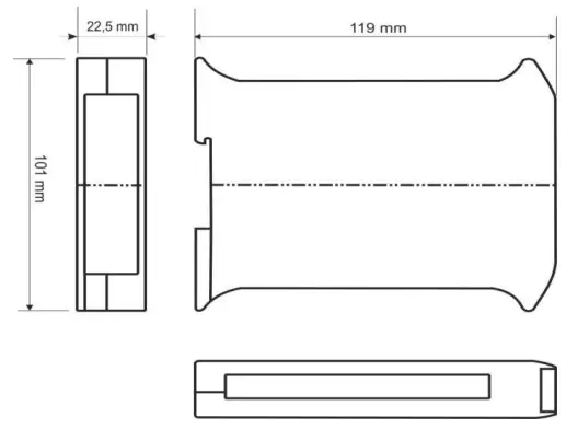
PHYSICAL CHARACTERISTICS
The gateway’s dimensions are: