![]() TA506 PicoBNC+ 10:1 Attenuating Lead
TA506 PicoBNC+ 10:1 Attenuating Lead
User Guide 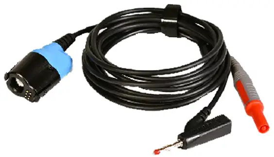
Introduction
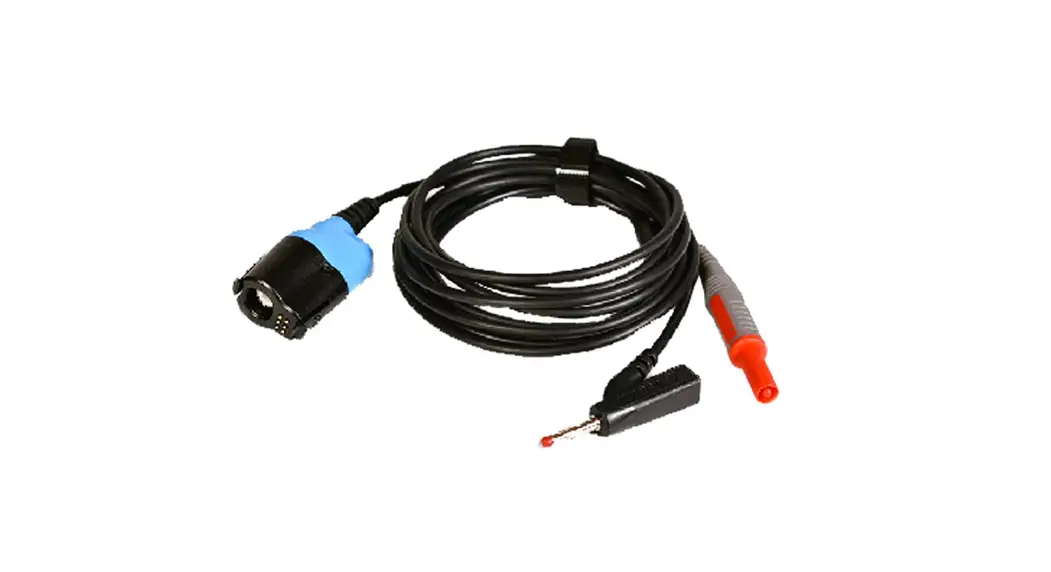
This passive high-impedance attenuating lead is designed for use with Pico Technology PicoBNC+ automotive oscilloscopes. It can be used to measure electrical signals up to the limits specified in this guide.
Warranty
Pico Technology warrants this oscilloscope accessory for normal use and operation within specifications for a period of one year from date of shipment and will repair or replace any defective product which was not damaged by negligence, misuse, improper installation, accident or unauthorized repair or modification by the buyer. This warranty is applicable only to defects due to material or workmanship. Pico disclaims any other implied warranties of merchantability or fitness for a particular purpose. Pico will not be liable for any indirect, special, incidental, or consequential damages (including damages for loss of profits, loss of business, loss of use or data, interruption of business and the like), even if Pico has been advised of the possibility of such damages arising from any defect or error in this manual or product.
Disposal![]() Your cooperation is required to help protect our environment. Therefore either return this product at the end of life to the manufacturer or ensure WEEE-compliant collection and treatment yourself. Do not dispose of as unsorted municipal waste.
Your cooperation is required to help protect our environment. Therefore either return this product at the end of life to the manufacturer or ensure WEEE-compliant collection and treatment yourself. Do not dispose of as unsorted municipal waste.
Safety information
To prevent possible electrical shock, fire, personal injury, or damage to the product, carefully read this safety information before attempting to install or use the product. In addition, follow all generally accepted safety practices and procedures for working with and near electricity.
The product has been designed and tested in accordance with the European standard publication EN 61010-031 (Hand-held probe assemblies) and left the factory in a safe condition.
The following safety descriptions are found throughout this guide:
A WARNING identifies conditions or practices that could result in injury or death.
A CAUTION identifies conditions or practices that could result in damage to the product or equipment to which it is connected.
Symbols
These safety and electrical symbols may appear on the product or in this guide:
| Symbol | Description |
| Direct current | |
| Earth (ground) terminal | |
| Terminal can be used to make a measurement ground connection. The terminal is NOT a safety or protective earth. | |
| Possibility of electric shock | |
| Caution | |
| Appearance on the product indicates a need to read these safety and operation instructions. | |
| Do not dispose of this product as unsorted municipal waste. | |
![]() WARNING
WARNING
To prevent injury or death, use the product only as instructed and use only accessories that have been supplied or recommended. Protection provided by the product may be impaired if used in a manner not specified by the manufacturer.
Maximum input ratings
The table and frequency derating plot below indicate the full-scale measurement range and overvoltage protection range for these probes. The full-scale measurement ranges are the maximum voltages that can be accurately measured by the probe. The overvoltage protection ranges are the maximum voltages that will not damage the lead.![]() WARNING
WARNING
To prevent electric shock, do not attempt to measure voltages outside of the specified full-scale measurement range.
| Attenuation | Full-scale measurement range | Overvoltage protection range |
| 10:01 | 400 V (DC + peak AC) | 400 V (DC + peak AC) |
![]() WARNING
WARNING
Signals exceeding the voltage limits in the table below are defined as “hazardous live“ by EN 61010.
| Signal voltage limits of EN 61010-031 | ||
| ±60 V DC | 30 V AC RMS | ± 42.4 V pk max. |
To prevent electric shock, take all necessary safety precautions when working on equipment where hazardous live voltages may be present.![]() WARNING
WARNING
These leads do not carry a measurement category rating. To prevent electric shock, do not connect to a utility power (line) voltage or a derived voltage that can carry the overvoltage transients that may be present. Measurement categories are defined in EN 61010-031 as follows:
| No measurement category (not in CAT II, CAT III, or CAT IV) | |
| Definition | For measurements performed on circuits not directly connected to a utility power supply. |
![]() WARNING
WARNING
To avoid overloading the lead, note that its maximum input voltage rating decreases as the frequency of the applied signal increases.
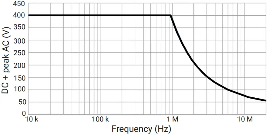 Voltage rating (V peak max.) v frequency curve
![]() CAUTION
CAUTION
Do not exceed the voltage rating marked on any accessory. If an accessory is not marked with a voltage rating on either the connector, cable or body, or if a protective finger guard is removed, do not exceed the EN 61010 “hazardous live” limits above.![]() WARNING
WARNING
To prevent injury or death, do not use the lead or an accessory if it appears to be damaged in any way, and stop use immediately if you are concerned by any abnormal operations.![]() CAUTION
CAUTION
Exceeding the voltage rating of any cable, connector or accessory can cause permanent damage to the lead and other connected equipment.![]() WARNING
WARNING
When connecting one or multiple accessories and a probe assembly together, the lowest voltage rating in the interconnected set applies.
Grounding
![]() WARNING
WARNING
The lead‘s ground connection through the oscilloscope is for measurement purposes only. The lead does not have a protective safety ground.
Never connect the ground input to any electrical power source. To prevent personal injury or death, use a voltmeter to check that there is no significant AC or DC voltage between the lead ground and the point to which you intend to connect it.![]() CAUTION
CAUTION
Applying a voltage to the ground input is likely to cause permanent damage to the lead and other connected equipment. It is good practice to connect the lead output to the measurement instrument and the ground lead to earth ground before connecting the lead to the circuit under test. Disconnect the lead input and the ground lead from the circuit under test before disconnecting the lead from the measurement instrument.
External connections![]() CAUTION
CAUTION
Take care to avoid mechanical stress or tight bend radii for all connected leads, including all coaxial leads and connectors. Mishandling will cause deformation and will degrade performance and measurement accuracy.
Environment
![]() WARNING
WARNING
To prevent injury or death, do not use in wet or damp conditions or near explosive gas or vapor.![]() CAUTION
CAUTION
To prevent damage, always store the device in appropriate environments.
| Storage | Operating | |
| Temperature | –20 to 80 °C | 0 to 80 °C |
| Humidity | 5 %RH to 95 %RH noncondensing | 5 %RH to 80 %RH noncondensing |
| Altitude range | Up to 2 000 m | |
| Pollution degree | 2. As defined in EN 61010-031. Only non-conductive pollution. Occasionally, however, a temporary conductivity caused by condensation must be accepted. | |
Care of the product
The lead contains no user-serviceable parts. Repair, servicing and calibration require specialized test equipment and must only be performed by Pico or an approved service provider. There may be a charge for these services unless covered by the Pico one-year warranty.
Inspect the lead and all connectors, cables and accessories before use for signs of damage.![]() WARNING
WARNING
To prevent electric shock do not tamper with or disassemble the probe, case parts, connectors or accessories.![]() CAUTION
CAUTION
When cleaning the product, use a soft cloth and a solution of mild soap or detergent in water. To prevent electric shock, do not allow liquids to enter the probe casing, as this will compromise the electronics or insulation inside.
Avoid mechanical shock to the probe in general to guarantee accurate performance and protection.
Specifications
| Probe characteristics | TA506 |
| Attenuation ratio | 10:01 |
| Bandwidth | 20 MHz |
| Rise time (calculated) | 17.5 ns |
| Input resistance | 10 MΩ ±2% |
| Input capacitance | 33 pF ±1 pF |
| Max. working voltage | 400 V pk |
| Total length | 2.85 m nominal |
| Weight | 100 g |
| United Kingdom headquarters Pico Technology James House Marlborough Road Colm worth Business Park Eaton Socony St. Neots PE19 8YP United Kingdom Tel: +44 (0)1480 396395 [email protected] [email protected] | North America regional office Pico Technology North America 320 N Glenwood Blvd. Tyler TX 75702 United States Tel: +1 800 591 2796 (toll free) [email protected] [email protected] | Germany regional office and EU authorized representative Pico Technology GmbH Im Rehwinkel 6 30827 Garbsen Germany Tel: +49 (0) 5131 907 6290 [email protected] |
![]() www.picotech.com
www.picotech.com![]() DO368-4 Copyright © 2022
DO368-4 Copyright © 2022
Pico Technology Ltd. All rights reserved.


