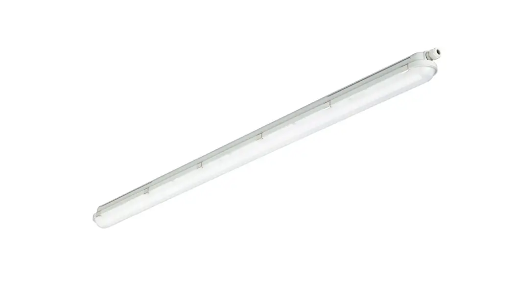
![]() CoreLine Waterproof
CoreLine Waterproof
WT120C G2 EL
User Guide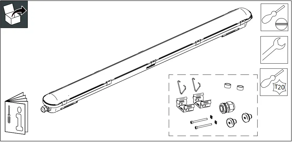 Please refer to the InterAct commissioning guide to enable wireless InterAct Ready functionality

WT120C G2 EL CoreLine Waterproof
| System light output (Lm) | System light output Emergency mode (Lm) |  | |
| WT120C G2 LED27S/840 PSU ELB3 L1200 | 2700 | 500 | 1,4 |
| WT120C G2 LED40S/840 PSU ELB3 L1200 | 4000 | 500 | 1,4 |
| WT120C G2 LED34S/840 PSU ELB3 L1500 | 3400 | 500 | 1,8 |
| WT120C G2 LED60S/840 PSU ELB3 L1500 | 6000 | 500 | 1,8 |
| WT120C G2 LED80S/840 PSU ELB3 L1500 | 8000 | 500 | 1,8 |
| WT120C G2 LED27S/840 PSD ELB3 L1500 | 2700 | 500 | 1,5 |
| WT120C G2 LED40S/840 PSD ELB3 L1500 | 4000 | 500 | 1,5 |
| WT120C G2 LED34S/840 PSD ELB3 L1500 | 3400 | 500 | 1,9 |
| WT120C G2 LED60S/840 PSD ELB3 L1500 | 6000 | 500 | 1,9 |
| WT120C G2 LED40S/840 IA1 ELB3 L1200 | 4000 | 500 | 1,5 |
| WT120C G2 LED60S/840 IA1 ELB3 L1500 | 6000 | 500 | 1,8 |
| WT120C G2 LED40S/840 WIA ELB3 L1200 | 4000 | 500 | 1,5 |
| WT120C G2 LED65S/840 WIA ELB3 L1500 | 6500 | 500 | 1,8 |
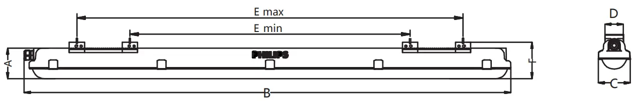
Dimension(mm) | Nr. of clips | |||||||
| A | B | C | D | E | Emin | Fmax | ||
| WT120C G2 LED27S L1200 | 76 | 1215 | 80 | 38 | 538 | 1062 | 85 | 10 |
| WT120C G2 LED40S L1200 | ||||||||
| WT120C G2 LED34S L1500 | 1515 | 838 | 1362 | 12 | ||||
| WT120C G2 LED60S L1500 | ||||||||
| WT120C G2 LED80S L1500 | ||||||||
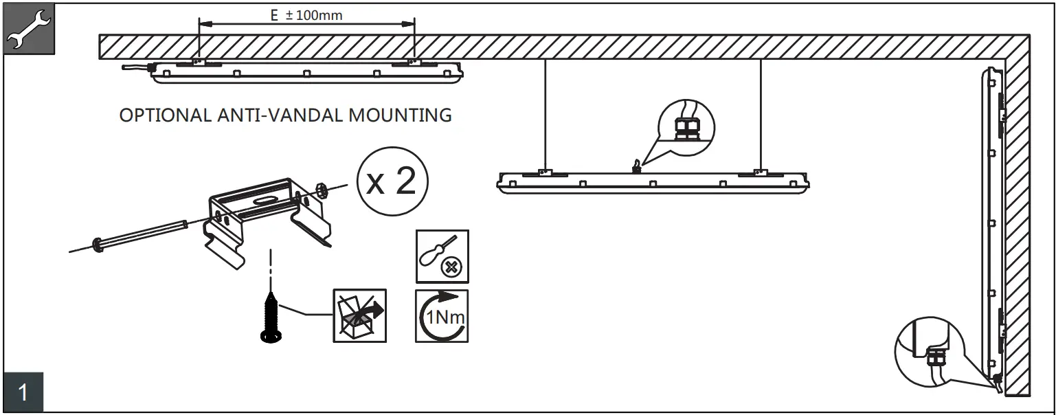
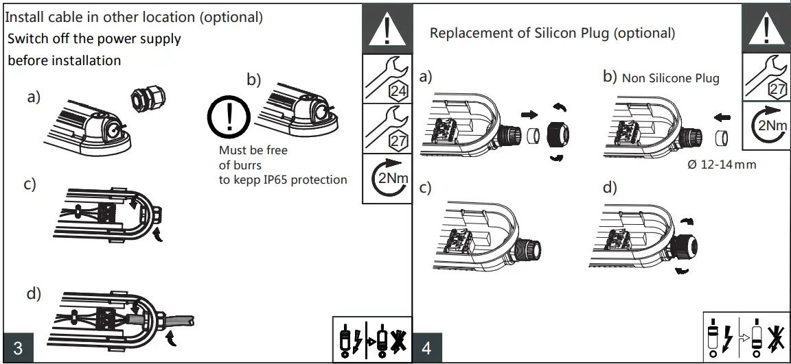
 Switch off the power supply before installation
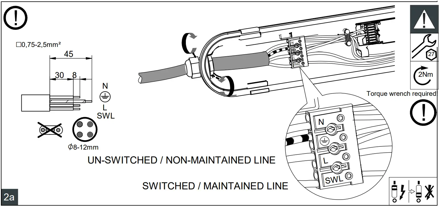
PSU & IA1 & WIA versions
![]() Switch off the power supply before installation
Switch off the power supply before installation
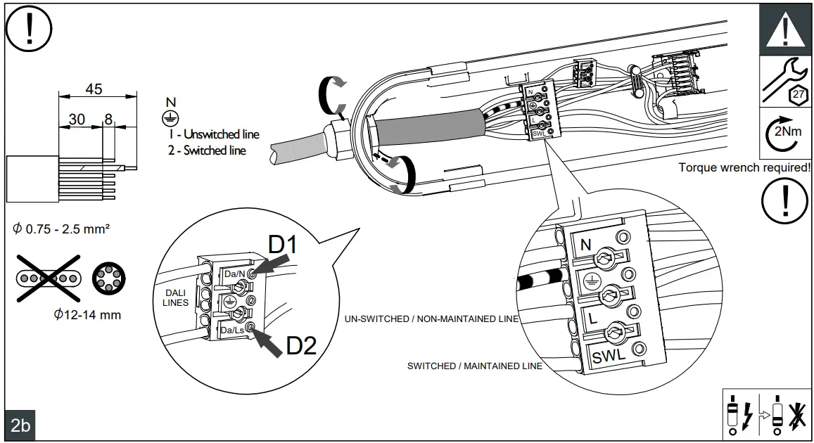
PSD versions
Through wiring
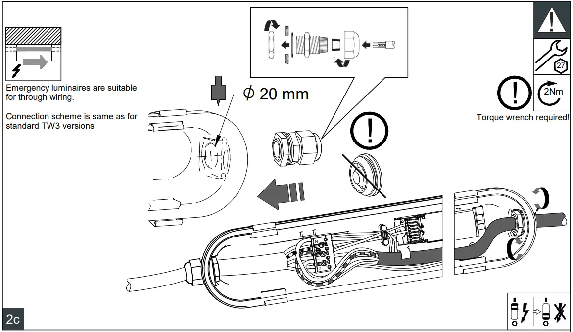
Use only optical sub-assembly that is delivered with housing in one box!
SERVICE
Light source (LED) is non-user replaceable. The light source contained in this luminaire shall only be replaced by the manufacturer or his agent or a similarly qualified person.
Do not touch electronic components!
Electronic components may be under high voltage. Caution, risk of electric shock
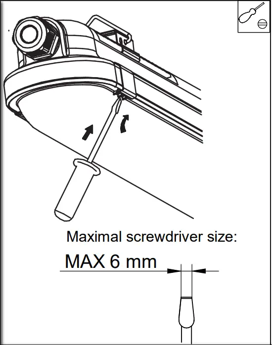
9a
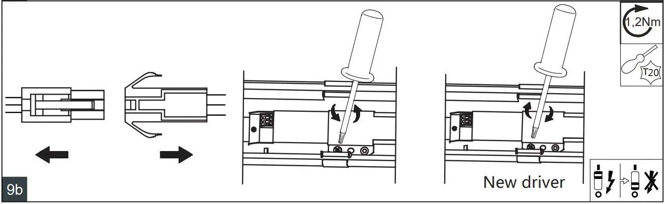 10
10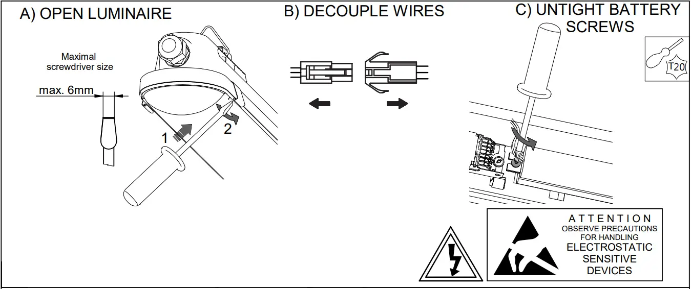
The batteries have a life expectancy of 4 years. Do not touch electronic components!
Electronic components may be under high voltage.
| LED27S | LED34S | LED40S | LED60S/65S | LED80S | |||||||||
| Driver type | PSU | PSD | PSU | PSD | PSU | PSD | IA1 | PSU | PSD | IA1 | WIA | PSU | PSD |
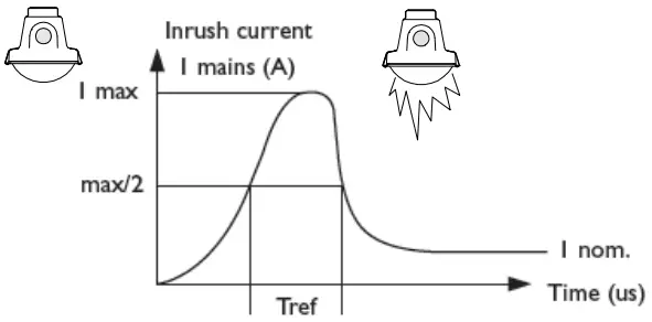
| Speak [A] | 3.58 | 19.4 | 5.16 | 19.4 | 5.16 | 19.4 | 22 | 5.56 | 20.9 | 22 | 19 | 6.9 | 20.9 |
| Tref [µs] | 40 | 200 | 47 | 200 | 47 | 200 | 270 | 47 | 192 | 270 | 230 | 58 | 192 |
| Max. Nr of products | |||||||||||||
| Drivers / MCB 16A type B [max.] | 80 | 30 | 60 | 30 | 60 | 30 | 22 | 45 | 29 | 22 | 24 | 30 | 29 |
| Drivers / MCB 10A type B [max.] | 50 | 18 | 37 | 18 | 37 | 18 | 13 | 28 | 18 | 13 | 15 | 18 | 18 |
| Drivers / MCB 16A type C [max.] | 136 | 51 | 102 | 51 | 102 | 51 | 37 | 76 | 49 | 37 | 40 | 51 | 49 |
| Drivers / MCB 10A type C [max.] | 80 | 31 | 62 | 31 | 62 | 31 | 22 | 46 | 30 | 22 | 24 | 31 | 30 |
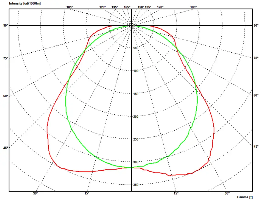
Light intensity distribution curves
Emergency mode
| Battery Unit | |
| Manufacturer: | Philips |
| Unit: | TrustSight 6.4V 4cell |
| 3000mAh battery LFP | |
| Technology: | Lithium-ion |
| Luminous flux: | 500 lm |
| Capacity: | 3000 mAh |
| Power: | 3 W |
| Duration: | 3 h |
| Nominal voltage: | 6,4 V |
Maintenance instructions
To assure the lighting quality of this unique LED lighting concept there are only a few instructions regarding the maintenance of this LED luminaire:
- Do not stare into the LED light beam.
- The luminaire shall be installed by a qualified electrician and wired in accordance with the latest IEE electrical regulations or national requirements.
- Above an average concentration of sulfur affects the useful lifetime of the product.
E.g: Light color changes from white to blue. Typically in chicken & pig farms.
Functional Notice for Emergency Lighting
Automatic emergency time selection
After installation and power up the driver will detect the battery and start the automatic detection process.
- During automatic detection, the indicator LED will light up with short green
- Between a minimum of 6 and a maximum of 30 seconds, the TrustSight driver will set the battery type (number of cells) and will set the emergency output power accordingly.
After that, the system is defined and fully operational. The battery type definition has an influence on the performance during the self-test and on the battery charge method. When the automatic battery detection process is disrupted, e.g. by switching off the permanent mains, the detection process is stopped and the TrustSight emergency driver will go into the emergency mode with the lowest output power. At the next power-up, the automatic detection process will start again.
Periodic testing
Periodic tests of emergency lighting luminaires must be performed according to EN50172 clauses 7.2.3 and 7.2.4. Switch on in the emergency mode each month by simulation of a failure of the supply to the normal lighting for a period sufficient to ensure that each lamp is illuminated. Twice per year, each luminaire shall be tested for its full rated duration (at least 3hrs).
For more information please consult the TrustSight Gen 3 Design guide. The latest version is available online.
| LED indicator (color/ flashing) | Error condition | Cause | Solution |
| Green / no flashing | System OK battery fully charged | ||
| Off | Mains off EM mode, Rest mode, test in progress | ||
| Green / slow (0.25s on, 1.25s off) | System OK battery is charging | ||
| Green / fast (0.25s on, 0.25s oft) | System OK recently tested (< 5 days, Australia mode only) | ||
| Red / no flashing | Battery voltage too high or too low | No battery connected | Connect battery |
| Wrong or bad battery connected | Replace battery | ||
| Red / fast (0.25s on, 0.25s off) | Output voltage too low or too high | Wrong LED load connected | Connect the right load and perform a functional test |
| No load connected or output shorted | Wrong connection | Connect the right load and perform a functional test | |
| Red /slow (0.25s on, 1.25s off) | Failed test due to battery | Battery end-of-life Charger failure | Replace the battery and perform a duration test. Replace driver |
| Red-green / fast Fast flashing: (on-time = 025s, off-time = 025s) Slow flashing: (on-time = 0.25s, off-time = 1.25s) | DALI device identification | ||
| Green/short on-time = 50ms, off-time = 095s) | Battery detection | ||
![]() Disconnect before servicing
Disconnect before servicing
Luminaire has basic insulation between Low Voltage supply and control conductors
GB The light source and/or control gear and/or the external flexible cable contained in this luminaire shall only be replaced by the manufacturer or his service agent or a similarly qualified person.
Storage, installation, use, operation, and maintenance of the products need to be performed exactly according to the instructions in this manual and/or other instructions as may be provided by us to guarantee the safe use of the product over its entire lifetime. Failure to adhere to these instructions will invalidate your entitlement to a warranty. Bolts with an indication of torque strength on the drawing need to be tightened using a calibrated torque wrench. Pre-assembled bolts need to be retightened again to the required torque specification to assure maximum strength over a lifetime
This product contains a light source of energy efficiency class: see table or label.
Zhaga-D4i and SR-certified compatibility – For Zhaga-D4i/SR-Certified based luminaires only Zhaga-D4i/SR-Certified components/sensors are to be used (see also:https://www.lighting.philips.co.uk/oem-emea/products/driving-connected-lighting / https://www.lighting.philips.co.uk/oem-emea/products/driving-connected-lighting). The functional compatibility of two SR-certified and/or Zhaga-D4i controllers/sensors to be used in combination, as well as the override possibility of any line-switch function used in an SR-based/Zhaga-D4i luminaire, is to be released by the master controller/sensor supplier. If using a NEMA 7-pin socket on an SR-based luminaire, a full system verification is required. Not following this advice can/will cause a risk of damage and non-compliance for which Signify cannot take any responsibility.
![]()
© 2021 Signify Holding
All rights reserved. Reproduction in whole or in part is prohibited without the prior written consent of the copyright owner. The information presented in this document does not form part of any quotation or contract, is believed to be accurate and reliable, and may be changed without notice. No liability will be accepted by the publisher for any consequence of its use. Publication thereof does not convey nor imply any license under patent- or other industrial or intellectual property rights.
Signify Holding The Netherlands


