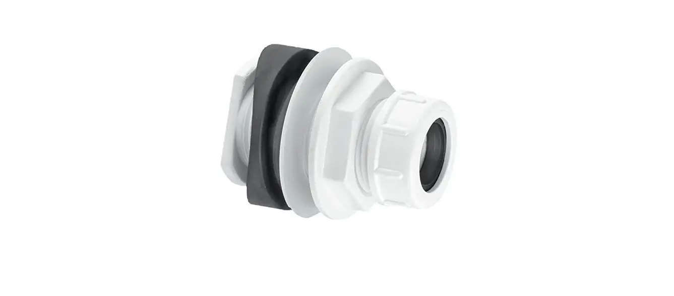
McALPINE BOSSCONN-1.25 Mechanical Boss Connector
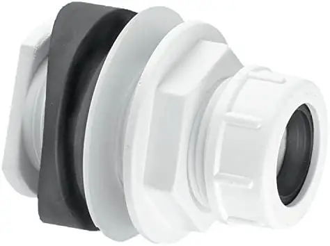
OVERVIEW
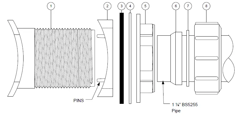
- Threaded Flange
- Rubber Seal for 110mm Soil Pipe
- Rubber seal for Square Section
- Rainwater Pipe
- Polythene Washer
- Backnut
- Rubber Compression Seal for 1 ¼” BS 5255 Pipe
- Plastic Washer for 1 ¼” BS 5255 Pipe
- Compression Nut for 1 ¼” BS 5255 Pipe
DIMENSION
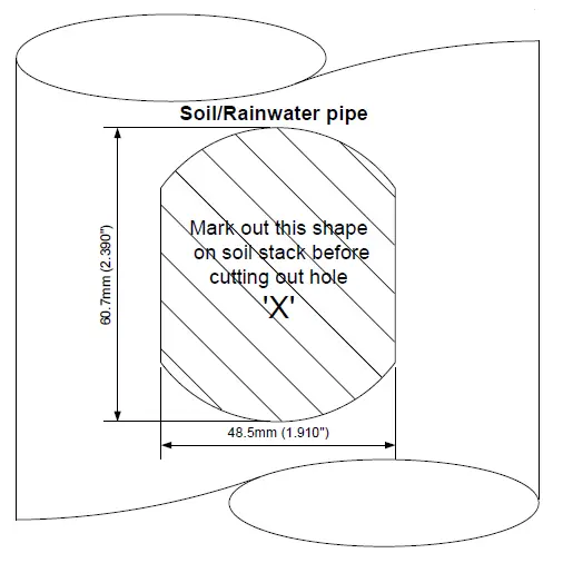
- Locate exact position where 1 ¼” pipe is required to connect and create hole in the soil/rainwater pipe to the dimensions of ‘X’. Use the template if required.
- Select the required rubber seal ‘2’ or ‘3’ and along with the polythene washer ‘4’ plus backnut ‘5’ fit to the threaded flange ‘1’
- Insert the threaded flange into the hole at a slight angle and twist through 90°.
- Push rubber seal and polythene washer along the threaded flange ensuring they are tight to the soil/rainwater pipe. In the case of the rubber seal ‘2’ , ensure the two small round pins are locked inside the soil pipe.
- Check that the threaded flange is at 90° and fully tighten the back nut making sure that the rubber seal and washer do not move out of position.
- Fit 1 ¼” pipe to the boss connector by placing ‘6’, ‘7’ and ‘8’ over the pipe, inserting the pipe into the connector and tightening the compression nut.
All water from sanitary pipework must be discharged via soil pipe
McALPINE
23/08/2021
L-BOSSCONN-1.25


