![]() MD1 Chem-Feed Multi-Diaphragm Metering Pump
MD1 Chem-Feed Multi-Diaphragm Metering Pump
Instruction Manual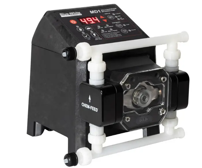
![]()
INTRODUCTION
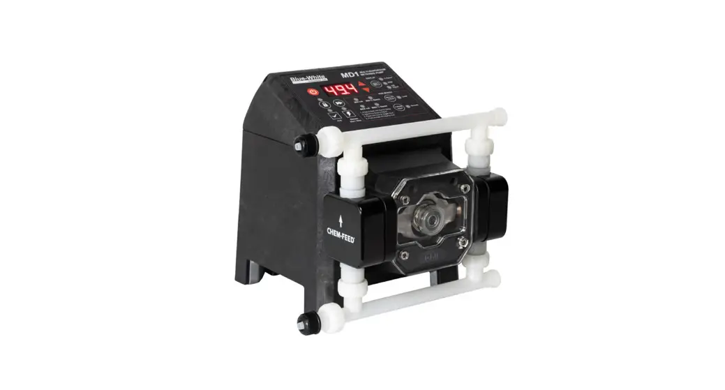
Congratulations on purchasing the 1 variable speed Multi-Diaphragm Metering Pump.
Please Note: Your new pump has been pressure tested at the factory with clean water before shipping.
This is part of our stringent quality assurance program at Blue-White Industries.
1.1 Available Models
Chem-Feed® MD1 Multi Diaphragm Metering Pump
| Feed Rate | Maximum Pressure PSI (bar) 3 | Maximum Temperature °F (°C)3 | Model Numbers | |
| GPH | LPH | |||
| 0.0007 – 7.70 | 0.0029 – 29.2 | 150 (10.3) | 185 (85) | 185 (85) |
ENGINEERING SPECIFICATIONS
| Maximum Working Pressure (Excluding pump tubes) | 150 PSI (10.3 bar) |
| Maximum Fluid Temperature | 185 F (85 C) |
| Maximum Viscosity | 1000 centipoise |
| Maximum Suction Lift | 20 ft. at 0 PSI |
| Ambient Operating Temperature | 14 F to 115 F (-10 C to 42 C) |
| Ambient Storage Temperature | -40 F to 158 F (-40 C to 70 C) |
| Operating Voltage | 115V60Hz 1 PH (0.6A max.) 220V50Hz 1 PH (0.3A max.) 230V60Hz 1 PH (0.3A max.) 230V50Hz 1 PH (0.3A max.) 240V50Hz 1 PH (0.3A max.) |
| Power Cord Options | 115V50/60Hz = NEMA 5/15 (USA) 230V50/60Hz = NEMA 6/15 (USA) 220V50/60Hz = CEE 7/VII (EU) 240V50/60Hz = AS 3112 (Australia/New Zealand) 230V50/60Hz = BS 1363/A (UK) |
| Motor | Brushless DC, 50W |
| Duty Cycle | Continuous |
| Motor SPeed Adjustment Range | 10,000:1 (0.01% – 100%) |
| Enclosure | NEMA 4X (IP66), Valox (PBT) & PA12 |
| Maximum Overall Dimensions | 7.25” W x 9” H x 10” D (18.5 W x 22.9 H x 25.2 D cm) |
| Product Weight | 8.5 lb. (3.8 Kg) |
| Approximate Shipping Weight | 15.5 lb. (5.9 Kg) |
| Approximate Shipping Dimensions | 10.5” W x 13.75” H x 11” D (26.7 W x 35 H x 28 D cm) |
CONSTRUCTION MATERIALS
3.1 Wetted Components
Pump Head Assembly
| Pump Head | PVDF |
| Adapter Connections | PVDF |
| Valve Cartridge | PVDF |
| Valve Balls | Ceramic |
| O-Ring Seals | TFE/P (optional EP) |
| Diaphragm | DiaFlex (optional Flex-A-Prene ) |
Injection/Back-Flow Check Valve
| Body & Insert | PVDF |
| Check Ball | Ceramic |
| Spring | Hastelloy C-276 |
| Ball Seat & Static Seal O-Ring | TFE/P (optional EP) |
Foot Valve/Strainer
| Body & Adapter | PVDF |
| Check Ball | Ceramic |
| Spring | Hastelloy C-276 |
| O-Ring Seal | TFE/P (optional EP) |
| Filter Screen | PVDF |
3.2 Non-wetted Components
| Enclosure | Valox (PBT) & PA12 |
| Drive Enclosure | PA12 |
| Pump Head Cover | Polycarbonate |
| Cover Screws | Stainless steel, polypropylene cap |
| DFD System Sensor Pins | Hastelloy C-276 |
| Power Cord | 3 conductor, SJTW-A water-resistant |
| Mounting Brackets and Hardware | 3/16” stainless steel screws GF nylon bracket |
Features
- Smooth chemical dosing, no pulsation dampener needed
- Diaphragm Failure Detection (DFD) system which senses diaphragm failure
- Rated for continuous duty
- Compatible with Blue-White Industries Flow Verification Sensor (FVS) system
- Remote Start/Stop
- Relay outputs include a single 250V/3A and a single solid state
- Multi-diaphragm metering with a turndown ratio of 10,000:1
- Built for long life at high pressures up to 150 PSI (10.3 bar)
- Output rates up to 7.70 GPH (29.2 LPH)
Agency Listings
| This pump is ETL listed to conform to the following: UL Standard 778 as a motor-operated water pump. CSA Standard C22.2 as process control equipment | |
| This pump complies with the Machinery Directive 98/37/EC, BS, EN 60204-1, Low Voltage Directive 73/23/EC BS EN 61010-1, EMC Directive 89/336/EC, BS EN 50081-1/BS EN 50082-1. | |
 | This pump is certified to NSF/ANSI Standard 61- Drinking Water System Components – Health Effects |
| Warning (Risk of electric shock) | |
| Caution (Refer to the user’s guide) | |
| Ground, Protective Conductor Terminal |
ENCLOSURE RATING
NEMA 4X is Constructed for either indoor or outdoor use to provide a degree of protection to personnel against incidental contact with the enclosed equipment; to provide a degree of protection against falling dirt, rain, sleet, snow, windblown dust, splashing water, and hose-directed water; and that will be undamaged by the external formation of ice on the enclosure.
IP66 No ingress of dust; complete protection against contact. Water projected in powerful jets against the enclosure from any direction shall have no harmful effects.
INSTALLATION
| The pump should be serviced by qualified persons only. If equipment is used in a manner not specified in this manual, the protection provided by the equipment may be impaired. | |
| Risk of chemical overdose. Be certain the pump does not overdose chemicals during backwash and periods of no flow in the circulation system. | |
| Always wear protective clothing, face shield, safety glasses, and gloves when working on or near your metering pump. Additional precautions should be taken depending on the solution being pumped. Refer to MSDS precautions from your solution supplier. | |
| All diagrams are strictly for guideline purposes only. Always consult an expert before installing a metering pump on specialized systems. The metering pump should be serviced by qualified persons only. | |
| Be sure that installation does not constitute a cross-connection with the drinking water supply. Check your local plumbing codes. | |
| The pump should be supplied by an isolating transformer or RCD (operating current less or equal 30 mA). |
Mounting Location
- Choose an area located near the chemical supply tank, chemical injection point, and electrical supply. Also, choose an area where the pump can be easily serviced.
- Finding a secure surface and using the provided mounting hardware, mount the pump close to the injection point. Keep the inlet (suction) and outlet (discharge) tubing as short as possible. Longer discharge tubing increases back pressure at pump head.
NOTE: Mounting the pump lower than the chemical container will gravity-feed chemicals into it. This “flooded suction” installation will reduce output error due to increased suction lift. A shut-off valve, pinch-clamp, or other means to halt gravity feed to the pump must be installed during servicing.
NOTE: Install a backflow prevention check valve at the discharge side of the pump to prevent the system fluid from flowing back through the pump during pump maintenance.
NOTE: It is recommended to have a pressure relief valve at the discharge side of the of the pump.
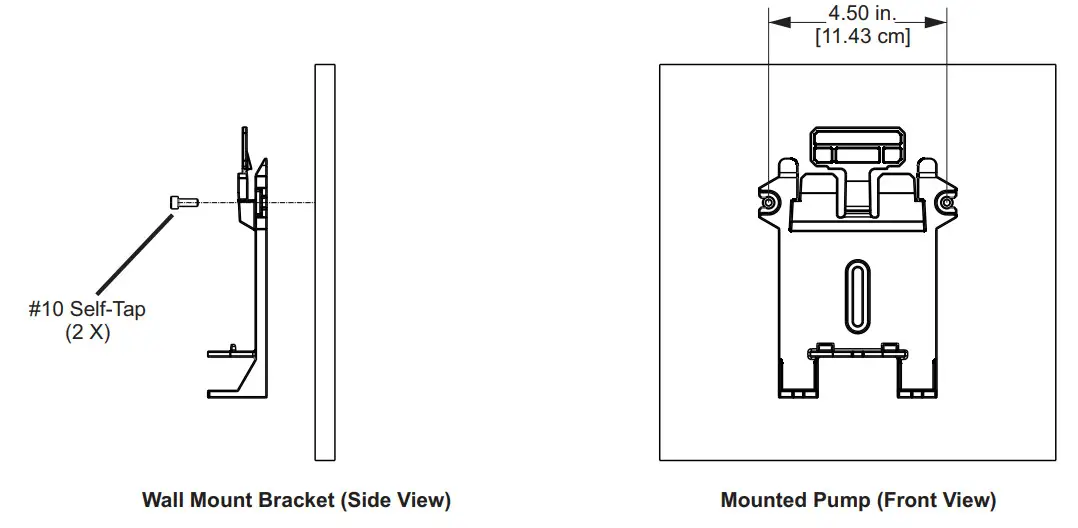
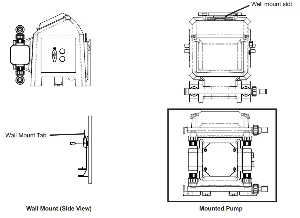
5.2 Wall Mounting
- Using the provided #10 self-tapping screws, mount the bracket to a secure wall that is located where it can be easily serviced.

- Lower the pump so that the tab on the wall mount is inserted into the slot located on the back of the pump. The pump will now be secured to the wall mount bracket.

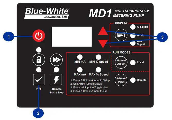
TOUCHPAD LAYOUT
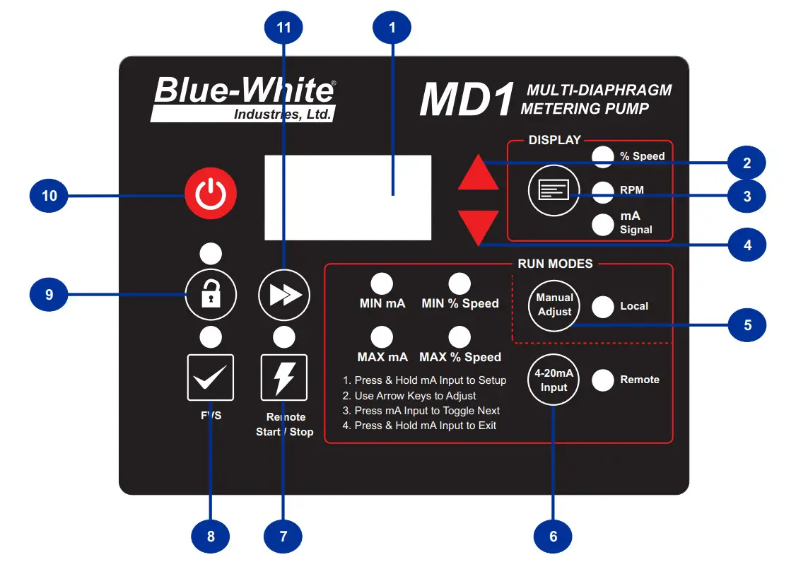
| Item Number | Item |
| 1 | LED/LCD Readout |
| 2 | Up Key |
| 3 | Rate Display Key |
| 4 | Down Key |
| 5 | Manual Adjust Control |
| 6 | 4-20mA Input Control |
| 7 | Remote Start/Stop Key |
| 8 | Flow Verification Sensor (FVS) Key |
| 9 | Lock-Out Key |
| 10 | Start & Stop Key |
| 11 | Prime Key |
6.1 IO Connection
![]() WARNING
WARNING
Risk of electric shock – All wiring must be insulated and rated 60V minimum.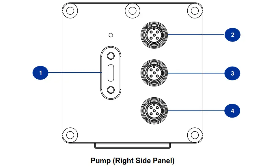
| Item Number | Item |
| 1 | USB-C Connector |
| 2 | M12 Input Connector 1 |
| 3 | M12 Input Connector 2 |
| 4 | M12 Output Connector |
M12 connectors are not included with the product.
Blue-White Industries requires any A-Type M12 connector with 5 position female sockets
M12 Connector

M12 Input Connector 1
| PIN | Function | Specifications | Reference |
| P1 | 4-20mA Input (+) | 120 Ohm Impedance, Non powered loop | (+) Positive |
| P2 | 4-20mA Input (-) | 120 Ohm Impedance, Non powered loop | (-) Negative |
| P3 | Not Used | ||
| P4 | Not Used | ||
| P5 | Not Used |
M12 Input Connector 2
| PIN | Function | Specifications | Reference |
| P1 | Remote Start / Stop | N.O. Dry Contact Closure | Open = Stop Gnd = Run |
| P2 | Ground | DC Ground | 0 VDC |
| P3 | FVS (+) | 15 VDC @ 60 mA | To power FVS sensor |
| P4 | FVS (-) | DC Ground (0 VDC) | FVS Ground Input |
| P5 | FVS (Signal) | Input Signal | Input for FVS Signal |
M12 Output Connector
| PIN | Function | Specifications |
| P1 | Remote Start / Stop | N.O. Dry Contact Closure |
| P2 | Ground | DC Ground |
| P3 | FVS (+) | 15 VDC @ 60 mA |
| P4 | FVS (-) | DC Ground (0 VDC) |
| P5 | FVS (Signal) | Input Signal |
4-20mA Input
![]() CAUTION
CAUTION
Proper eye and skin protection must be worn when installing and servicing the pump.
7.1 Selecting 4-20mA input mode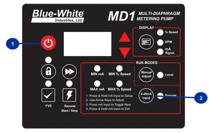
Directions
- Confirm that the pump is in the OFF position
- Press the 4-20mA Input button
7.2 Programming 4-20mA input mode
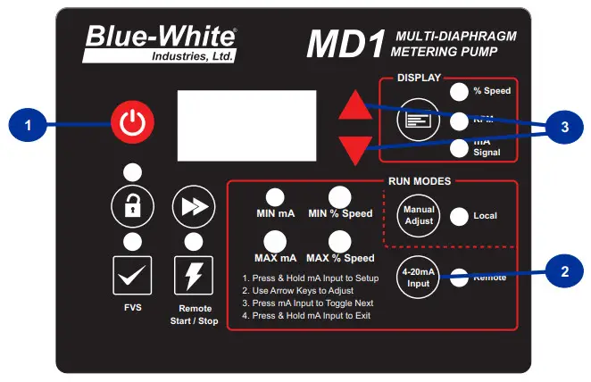
Directions
- Confirm that pump is in the OFF position.
- Press and hold the 4-20mA Input button.
- MIN mA light will illuminate. Use arrow keys to toggle it mA value for the pump to operate at
- Press the 4-20mA Input button for MIN % Speed light to illuminate
- Use arrow keys to toggle the MIN % Speed value for the pump to operate.
- Press the 4-20mA Input button for the MAX mA light to illuminate.
- Use arrow keys to toggle the MAX mA value for the pump to operate.
- Press the 4-20mA Input button for the MAX % Speed light to illuminate.
- Use arrow keys to toggle the MAX % Speed value for the pump to operate.
- Press and hold the 4-20mA Input button to exit programming mode.
Programming FVS (Flow Verification Sensor)
Directions
- Confirm that the pump is in the OFF position
- Press and hold the FVS button
- Toggle the up/down arrow until desired trigger time is shown (seconds)
- Press and hold the FVS button to set
NOTE: Alarm Delay Time range is 1-20 seconds
POWER CONNECTIONS
| Risk of electric shock – cord-connected models are supplied with a grounding conductor and grounding-type attachment plug. To reduce the risk of electric shock, be certain that it is connected only to a properly grounded, grounding-type receptacle. | |
| Electrical connections and grounding (earthing) must conform to local wiring codes. | |
| Ensure to connect the pump to the proper supply voltage. Using the incorrect voltage will damage the pump and may result in injury. The voltage requirements are printed on the pump serial label. |
- Use the voltage for which the power cord is rated.
- Do not strap together control (input/output) cables and power cables.
- When there is a power interruption, the pump, which has an auto-restart feature, will restore the pump to the operating state it was in when the power was lost.
- POWER: 115V60Hz (0.6A max.), 220V50Hz (0.3A max.), 230V60Hz (0.3A max.), 230V50Hz (0.3A max.), 240V50Hz (0.3A max.)
NOTE: Contact a licensed electrician when there is doubt regarding the electrical installation.
OUTPUT ADJUSTMENT
The speed of the pumping mechanism is adjustable from 0.01 to 100 % motor speed (0.01 RPM to 100 RPM).
DFD (Diaphragm Failure Detection)
The MD1 is equipped with a Diaphragm Failure Detection System which is designed to stop the pump and provide an output alarm in the event the diaphragm should rupture and chemical enters the pump head.
This system is capable of detecting the presence of a large number of chemicals including Sodium Hypochlorite (Chlorine), Hydrochloric (muriatic) Acid, Sodium Hydroxide, and many others. The system will not be triggered by water (rain, condensation, etc.) or lubricants.
If the system has detected chemicals, the pump diaphragm must be replaced and the pump head must be thoroughly cleaned.
Failure to clean the pump head will void the warranty.
If a DFD alarm occurs, the pump will stop, close an alarm output, and the screen will flash DFD with an alarm icon.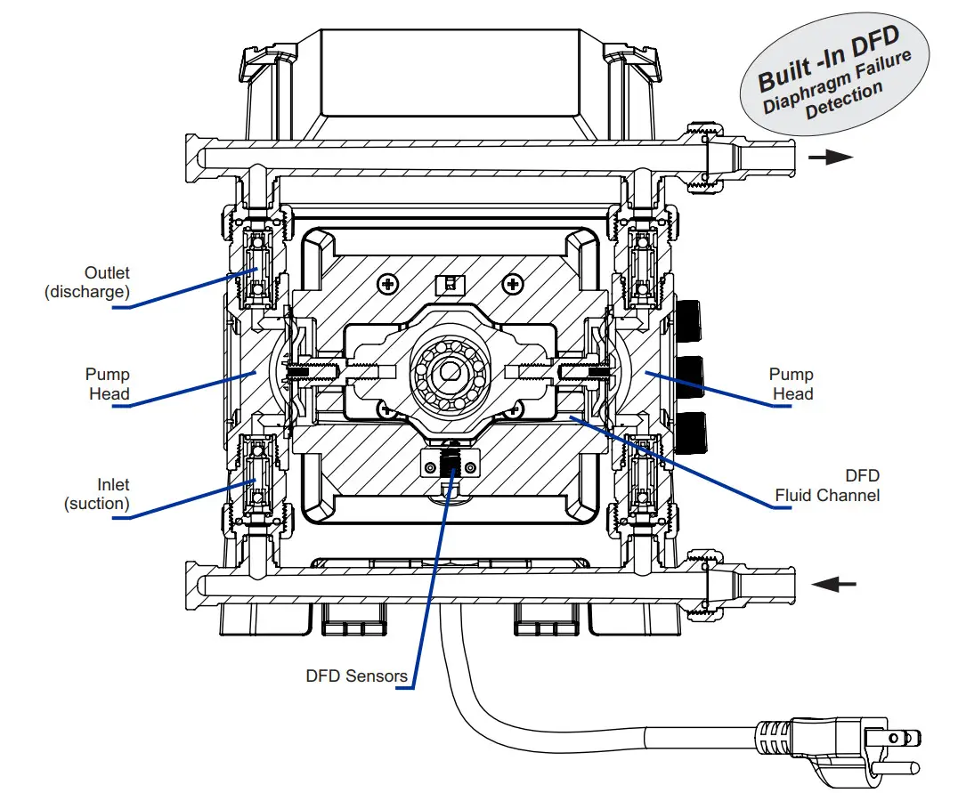
Pump Maintenance
| Prior to service, pump clean water through the pump and suction/discharge line to remove chemicals. | |
| Always wear protective clothing, face shield, safety glasses, and gloves when working on or near your metering pump. Additional precautions should be taken depending on the solution being pumped. Refer to MSDS precautions from your solution supplier. |
12.1 Routine Inspection and Maintenance
The pump requires very little maintenance. However, the pump and all accessories should be checked weekly. This is especially important when pumping chemicals. Inspect all components for signs of leaking, swelling, cracking, discoloration or corrosion. Replace worn or damaged components immediately.
Cracking, crazing, and discoloration during the first week of operation are signs of a severe chemical attack. If this occurs, immediately remove the chemical from the pump. Determine which parts are being attacked and replace them with parts that have been manufactured using more suitable materials. The manufacturer does not assume responsibility for damage to the pump that has been caused by a chemical attack.
12.2 Cleaning Pump
The pump will require occasional cleaning, especially Injection fitting, Foot Valve / Strainer, and pump head valves.
The frequency will depend on the type and severity of the service.
Inspect and replace pump head valves as required.
Periodically clean injection/check valve assembly, especially when injecting fluids that calcify such as sodium hypochlorite. These lime deposits and other build-ups can clog fitting, increase back pressure and interfere with check valve operation.
Periodically clean suction strainer.
Periodically inspect pump housing (enclosure) for the chemical attack. Protect pump housing from continuous exposure to chemicals, such as drips or fumes from surrounding equipment and plumbing.
12.3 Replacing the Pump Diaphragm
When changing the diaphragm, the pump head chamber and pump head cover should be wiped free of any dirt and debris. The pump stroke must be FORWARD when installing the diaphragm, and BACK when installing and tightening the pump head.
When replacing the pump diaphragm, note the order of parts per the illustration below: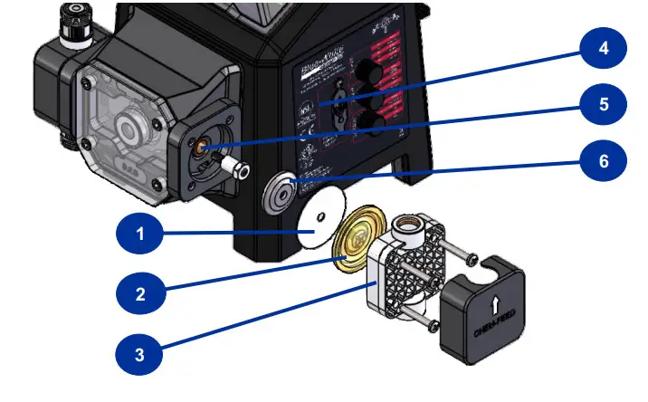
| Item | Item |
| 1 | PTFE Ring |
| 2 | Diaphragm |
| 3 | Pump Head |
| 4 | Pump |
| 5 | Piston |
| 6 | Backup Washer |
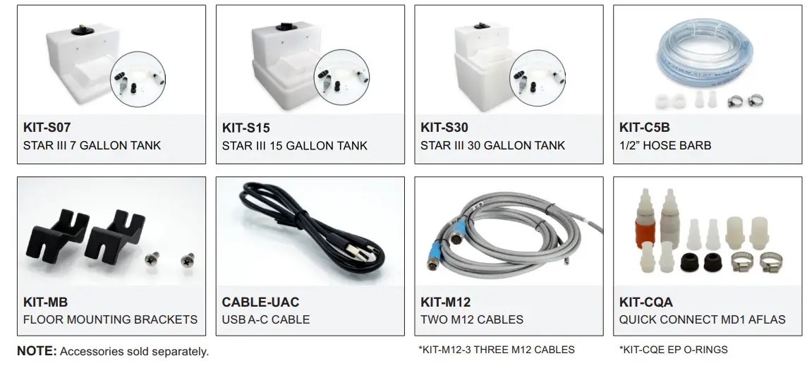
ACCESSORIES
The following accessories are available for the MD1 Multi-Diaphragm Metering Pump. Please visit Blue-white.com for more information. All accessories are sold separately.
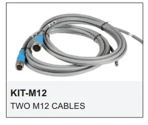
KIT-M12
Kit contains Two M12 cables.
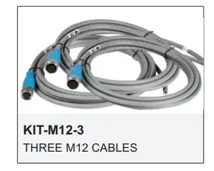
KIT-M12-3
Kit contains Three M12 cables.
CABLE-UAC
Kit contains One 3’ USB-A to USB-C cable.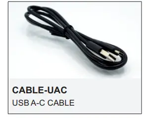
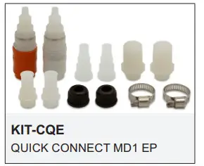
KIT-CQE
Kit contains: One discharge fitting with EP o-rings installed (red),One suction fitting with EP o-rings installed (white), Two tube nuts, Two 1/2” hose barb quick connect adapters, Two 1/2” M/NPT quick connect adapters, Two quick disconnect adapters and Two #5 hose clamps.
KIT-CQA
Kit contains: One discharge fitting with Aflas o-rings installed (red),One suction fitting with Aflas o-rings installed (white), Two tube nuts, Two 1/2” hose barb quick connect adapters, Two 1/2” M/NPT quick connect adapters, Two quick disconnect adapters and Two #5 hose clamps.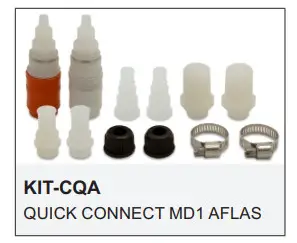
KIT-C5B
Kit contains: Two union nuts, Two 1/2” hose barb adapters, Two #5 hose clamps, One 2 1/2’ clear reinforced PVC tube and One 5’ 5/8” suction tube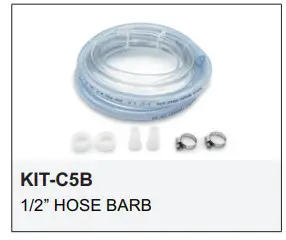
KIT-S7
Kit contains One 7 gallon tank, One 3/8” suction tube, One 3/8” discharge tube, One-foot valve and strainer, and One mounting bracket with screws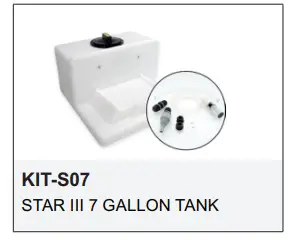
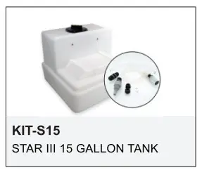
KIT-S15
Kit contains 15-gallon tank, One 3/8” suction tube, One 3/8” discharge tube, One-foot valve and strainer, and One mounting bracket with screws
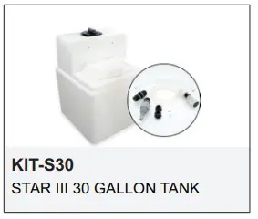
KIT-S30
Kit contains: One 30-gallon tank, One 3/8” suction tube, One 3/8” discharge tube, One-foot valve and strainer, and One mounting bracket with screws
KIT-MB
Kit contains: Two-floor mounting brackets and Two screws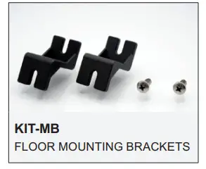
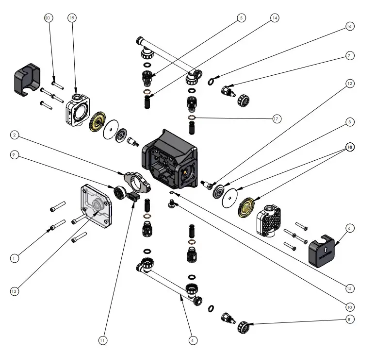
REPLACEMENT PARTS LIST
| ITEM NO. | PART NUMBER | DESCRIPTION | QTY. |
| 1 | 90011-264 | SCREW 10-32 X .375 SOC CAP SS | 4 |
| 2 | 76001-945 | HYPER-DRIVE MD1 MACHINED | 1 |
| 3 | 90006-600 | BACK-UP WASHER HD .100″ THICK | 2 |
| 4 | 71010-730 | MANIFOLD NUT UNION AND FLANGE SPIN WELD MD1 | 2 |
| 5 | 90002-707 | ADAPTER CART MD1 | 4 |
| 6 | 70004-539 | P/HEAD COVER CHEM-FEED MD1 | 2 |
| 7 | 90002-708 | .37T ADAPTER | 2 |
| 8 | 90002-712 | NUT UNION MD-1 MOLDED PVDF | 2 |
| 9 | 70000-131 | CAM C-1500 S/A .125″ COMPLETE | 1 |
| 10 | 90011-261 | SCREW 5/16-18 X .50″L PHIL NYLON BLK MD1 | 1 |
| 11 | 76002-034 | CAP DFD MD1 | 1 |
| 12 | 76001-966 | STANDOFF HEX MALE-FEMALE THREADED MD1 MACH. | 2 |
| 13 | 71010-745 | COVER PUMPHEAD MOUNT ASSY MD1 | 1 |
| 14 | 71000-392 | CART BULLET DOUBLE AFLAS PVDF | 4 |
| 15 | 90003-003 | 0-RING 010 EP | 1 |
| 90003-004 | 0-RING 010 VITON | ||
| 16 | 90003-581 | 0-RING 2-112 AFLAS | 6 |
| 90003-208 | 0-RING 2-112 EP | ||
| 17 | 90003-125 | 0-RING 015 AFLAS | 4 |
| 90003-015 | 0-RING 015 EP | ||
| 18 | KIT-CDV | DIAPHRAGM MD1 PVDF | 2 |
| KIT-CDE | DIAPHRAGM MD1 FLEX-A-PRENE | ||
| 19 | 70004-096 | PUMP/HD HDN LG PVDF V STAMP | 2 |
| 70004-097 | PUMP/HD HDN LG PVDF E STAMP | ||
| 20 | 90011-141 | SCREW 10-32 X1.25 PAN PHIL SS | 8 |
14.1 EXPLODED VIEW
| Error Code E01 | Explanation Motor Over Current | Troubleshooting Ensure that diaphragm is installed properly |
| 0.00E+00 | Over Voltage | Check power supply output voltage |
| 0.00E+00 | Under Voltage | Check power supply output voltage |
| 0.00E+00 | Temperature exceeds 75°C at the control | Check ambient conditions, and restart the pump once cooled to ambient temperature |
| 0.00E+00 | Inverter Error | Contact Blue-White Industries at (714) 893-8529 [email protected] |
| 0.00E+00 | No Motor Connection | Contact Blue-White Industries (714) 893-8529 [email protected] |
| 0.00E+00 | Motor Stall | Ensure that diaphragm is installed properly |
| 0.00E+00 | Capacitor bank charging error | Contact Blue-White Industries (714) 893-8529 [email protected] |
| 0.00E+00 | Communication error at display | Contact Blue-White Industries (714) 893-8529 [email protected] |
WARRANTY
16.1 Limited Warranty
The pump is a quality product and is warranted for 36 months from date of purchase (proof of purchase is required). The pump will be repaired or replaced at our discretion. The pump head and roller assembly are warranted against damage from a chemical attack when the proper Diaphragm Failure Detection(DFD) system instructions and maintenance procedures are followed.
16.2 What is not Covered
- Pump diaphragm and rubber components – They are perishable and require periodic replacement
- Pump removal, or re-installation, and any related labor charge.
- Freight to the factory.
- Pumps that have been tampered with, or in pieces.
- Damage to the pump that results from misuse, carelessness (such as chemical spills) on the enclosure, abuse, lack of maintenance, or alteration that is out of Blue-White Industries, Ltd.’s control.
- Pumps are damaged by faulty wiring, power surges, or acts of nature.
Blue-White Industries, Ltd. does not assume responsibility for any loss, damage, or expense directly or indirectly related to or arising out of the use of its products. Failure must have occurred due to a defect in material or workmanship and not as a result of the operation of the product other than in normal operation as defined in the pump operation manual.
The warranty status is determined by the pump’s serial label and the sales invoice or receipt. The serial label must be on the pump and be legible. The warranty status of the pump will be verified by Blue-White Industries, Ltd. or a factory-authorized service center.
16.3 Obtaining In-Warranty Repair
Contact the factory to obtain an RMA (Return Material Authorization) number. Carefully pack the pump to be repaired. It is recommended to include foot strainer and injection/check valve fitting since these devices may be clogged and part of the problem. Please enclose a brief description of the problem as well as the original invoice or sales receipt, or copy showing the date of purchase. Prepay all shipping costs. COD shipments will not be accepted. Warranty service must be performed by the factory or an authorized ProSeries service center. Damage caused by improper packaging is the responsibility of the sender. When In-Warranty repair or replacement is completed, the factory pays for return shipping to the dealer or customer.
16.4 Product Use Warning
Blue-White products are manufactured to meet the highest quality standards in the industry. Each product instruction manual includes a description of the associated product warranty and provides the user with important safety information.
Purchasers, installers, and operators of Blue-White products should take the time to inform themselves about the safe operation of these products. In addition, Customers are expected to do their own due diligence regarding which products and materials are best suited for their intended applications. Blue-White is pleased to assist in this effort but does not guarantee the suitability of any particular product for any specific application as Blue-White does not have the same degree of familiarity with the application that the customer/end-user has. While Blue-White will honor all of its product warranties according to their terms and conditions, Blue-White shall only be obligated to repair or replace its defective parts or products in accordance with the associated product warranties. BLUE-WHITE SHALL NOT BE LIABLE EITHER IN TORT OR IN CONTRACT FOR ANY LOSS OR DAMAGE WHETHER DIRECT, INDIRECT, INCIDENTAL, OR ONSEQUENTIAL, ARISING OUT OF OR RELATED TO THE FAILURE OF ANY OF ITS PARTS OR PRODUCTS OR OF THEIR NONSUITABILITY FOR A GIVEN PURPOSE OR APPLICATION.
16.5 Chemical Resistance Warning
Blue-White offers a wide variety of wetted parts. Purchasers, installers, and operators of Blue-White products must be well informed and aware of the precautions to be taken when injecting or measuring various chemicals, especially those considered to be irritants, contaminants or hazardous. Customers are expected to do their own due diligence regarding which products and materials are best suited for their applications, particularly as it may relate to the potential effects of certain chemicals on Blue-White products and the potential for adverse chemical interactions.
Blue-White tests its products with water only. The chemical resistance information included in this instruction manual was supplied to Blue-White by reputable sources, but Blue-White is not able to vouch for the accuracy or completeness thereof.
While Blue-White will honor all of its product warranties according to their terms and conditions, Blue-White shall only be obligated to repair or replace its defective parts or products in accordance with the associated product warranties.
BLUE-WHITE SHALL NOT BE LIABLE EITHER IN TORT OR IN CONTRACT FOR ANY LOSS OR DAMAGE, WHETHER DIRECT, INDIRECT, INCIDENTAL, OR CONSEQUENTIAL, ARISING OUT OF OR RELATED TO THE USE OF CHEMICALS IN CONNECTION WITH ANY BLUE-WHITE PRODUCTS.
ACRONYMS
| °C | Celsius |
| °F | Fahrenheit |
| AC | Alternating current |
| bar | Unit of pressure |
| CIP | Clean-in-place |
| cm | Centimeters |
| COD | Cash on Delivery |
| D | Depth |
| DC | Direct current |
| DFD | Diaphragm Failure Detection |
| EEE | Electrical and electronic equipment |
| EP | Ethylene propylene |
| ETL | Electrical Testing Labs/Intertek |
| EU | European Union |
| FDA | Food and Drug Administration |
| FKM | Fluoroelastomer |
| FVS | Flow Verification Sensor |
| GF | Glass fiber |
| GPD | Gallons per day |
| GPH | Gallons per hour |
| H | Height |
| Hz | Inside diameter |
| 10 | Input/Output |
| Kg | Kilogram |
| lb. | Pound |
| LLDPE | Linear low-density polyethylene |
| LPH | Liters per hour |
| mA | Milliampere |
| min | Minute |
| mL | Milliliters |
| MSDS | Material Safety Data Sheet |
| N.C. | Normally Close |
| N.O. | Normally Open |
| NPT | National Pipe Thread |
| NSF | National Sanitation Foundation |
| OD | Outside diameter |
| P.N. | Part Number |
| PBT | Polybutylene Terephthalate |
| PE | Polyethylene |
| PSI | Pounds per Square Inch |
| PVC | Polyvinyl chloride |
| PVDF | Polyvinylidene fluoride |
| RCD | Residual-current device |
| Rev. | Revision |
| RMA | Return Material Authorization |
| RPM | Revolutions per minute |
| SIP | Steam-in-place |
| SS | Solid state |
| TFD | Tube Failure Detection |
| TFE/P | Tetrafluoroethylene propylene |
| UL | Underwriters Laboratories |
| US | United States |
| V | Volt |
| W | Watt |
| W | Width |
| WEEE | Waste Electrical and Electronic Equipment |
Model Number Matrix
CHEM-FEED® Model Number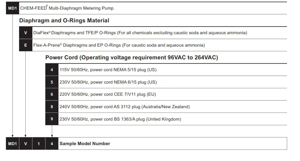
Accessories
![]() Users of electrical and electronic equipment (EEE) with the WEEE marking per Annex IV of the WEEE Directive must not dispose of end-of-life EEE as unsorted municipal waste, but use the collection framework available to them for the return, recycle, recovery of WEEE and minimize any potential effects of EEE on the environment and human health due to the presence of hazardous substances.
Users of electrical and electronic equipment (EEE) with the WEEE marking per Annex IV of the WEEE Directive must not dispose of end-of-life EEE as unsorted municipal waste, but use the collection framework available to them for the return, recycle, recovery of WEEE and minimize any potential effects of EEE on the environment and human health due to the presence of hazardous substances.
The WEEE marking applies only to countries within the European Union (EU) and Norway. Appliances are labeled in accordance with European Directive 2002/96/EC.
Contact your local waste recovery agency for a Designated Collection Facility in your area.
![]() 5300 Business Drive Huntington Beach, CA 92649 USA
5300 Business Drive Huntington Beach, CA 92649 USA
TEL: 714-893-8529 FAX: 714-894-9492
www.blue-white.com
[email protected]
[email protected]


