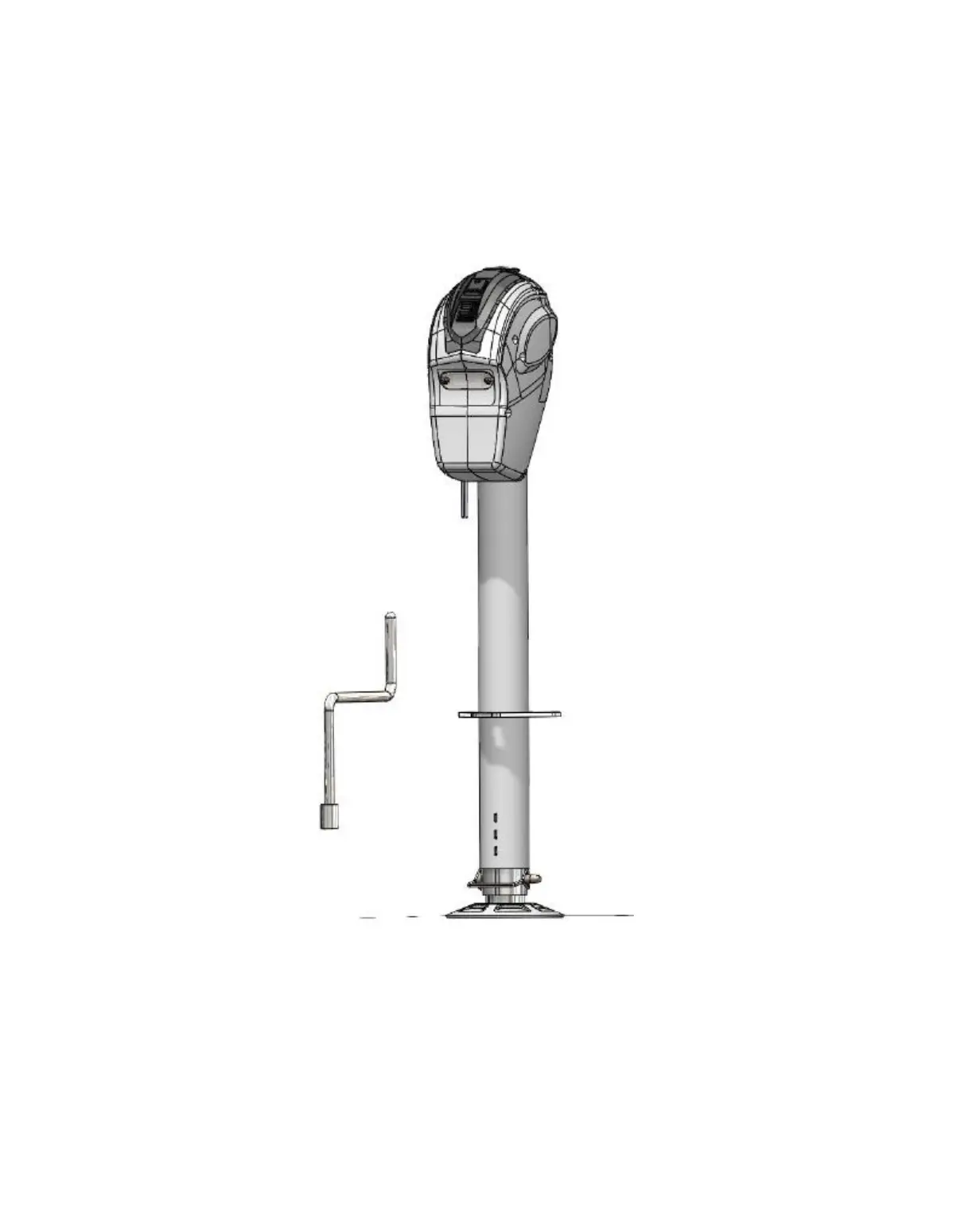
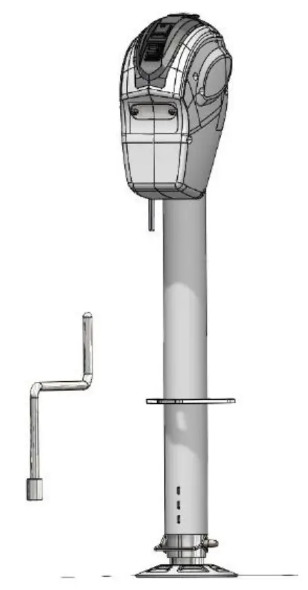
URIAH PRODUCTS #10201091P 5000lbs.12V DC Electric Trailer Jack
 WARNING:
Read, Understand, Follow and Save These Instructions.
Failure to follow all warnings and instructions may result in product failure, property damage, serious personal injury.
The warnings, cautions, and instructions discussed in this instruction manual cannot cover all possible conditions or situations that could occur. It must be understood by the operator that common sense and caution are factors which cannot be built into this product, but must be supplied by the operator.
INTENDED USE
This electric trailer tongue jack is a 12V motor-driven jack that makes coupling and uncoupling from
the hitch on travel trailers and boat trailers an easier operation. New industrial design cover is extremely waterproof. Improved LEDs shine down onto your ball and coupler where light is needed the most.
TECHNICAL SPECIFICATIONS
SPECIFICATIONS
- Model no.: 10201091P
- Maximum Lift Capacity: 5000 lb
- Travel: Full 22-1/2” stroke (18” power plus 4-1/2” manual drop leg extension)
- Height Range: 9″ to 31-1/2″
- Type: 12V DC A-Frame
- Outer Tube Diameter: 2-1/4”
- Foot Pad: Removable 4-1/2 in. Drop Leg
Components of Kit and Tools Required
- Three Grade 5, 1in. Long, 3/8in.-16 UNC Bolts and Lock nuts (included)
- Three 3/8in. Flat Washers (included)
- 7/16 in. Wrench (owner supplied, not included)
- Torque Wrench (owner supplied, not included)
- Wire Cutters (owner supplied, not included)
- Wire Strippers (owner supplied, not included)
- Crimpers or Soldering Iron (owner supplied, not included)
SAVE THESE INSTRUCTIONS
IMPORTANT SAFETY CONSIDERATIONS
JACK USE AND CARE
- Do not modify the jack in any way. Unauthorized modification may impair the function and/or safety and could affect the life of the equipment. There are specific applications for which the jack was designed.
- Always check for damaged or worn out parts before using the jack. Broken parts will affect the jack operation. Replace or repair damaged or worn parts immediately.
- Do not force the trailer jack. Do not attempt to lift more than the maximum lifting capacity of 5000-lb.
- Never attempt to adjust the drop leg when there is any load on the jack. When using the drop foot or drop leg, make certain the supplied pin is fully inserted through both sides of the inner tube and the drop tube before using the jack.
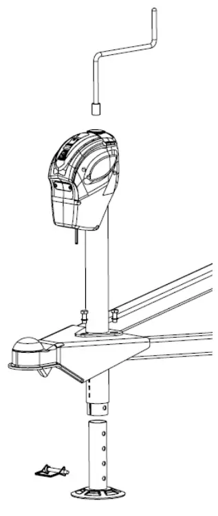
INSTALLATION INSTRUCTIONS
Before installation, compare the lift capacity of the electrical jack with your trailer to ensure safe operation of the jack.
- Park the trailer on a level surface and block the wheels.
- This trailer jack has been designed to attach to the top surface of the A-frame coupler.
- Disconnect the trailer battery.
- Detach the drop leg (#23) of the jack by removing the lock pin (#22) and sliding it out.
- Position the drop leg (#23) in line with the mounting hole with the foot of the drop leg on the ground.
- Support the trailer tongue by the frame with jack stands (not included).
- If replacing an old jack, remove the old jack from the coupler, saving the washers and bolts.
- Insert the electric jack through the A-frame coupler hole and align the bolt holes so the motor housing is facing forward towards the tow vehicle.
- Secure the jack with three Grade 5, 3/8in.-16UNC bolts and washers. Remove paint from around one bolt hole on the jack, and from around the matching bolt hole on the trailer tongue. If the paint layer is thick, add a flat washer between the jack and the trailer to provide good contact. Exposed metal can be painted after assembly to prohibit corrosion. Bolts should be tightened to 15-20 ft.-lbs
Tip: The salvaged bolts from the old jack are acceptable for reuse if they are Grade 5 and in good condition. - Connect the BLACK wire lead from the jack directly to the positive (+) terminal of the battery or junction box. This unit has a built-in circuit breaker which automatically trips and resets if the amperage is too high. Now connect the WHITE ground wire to the negative (-) battery terminal or to the trailer frame.
- Check for proper installation by pressing the up/down switch for extending/retracting the jack. Also check that the light switch turns on the LED light.
- After checking for proper operation, be sure to reattach the drop leg to the inner tube of the jack using the lock pin.
- Retract the jack completely.

OPERATION
- Park the trailer on a level surface and block the wheels.
Tip: For nighttime hookups, turn the light switch (#29) ON to illuminate your work area. - Before operating the jack, extend the drop leg foot (#23) to the appropriate length and secure in place with the 3/8” safety lock pin (#22) provided.
 WARNING: Do not stack blocks under the jack’s foot to increase the height. Stacked blocks may become unstable and fall.
 - Extend the jack by pushing the operating switch (#30) UP.
Note: Under heavy use, the internal circuit breaker may open, causing the motor to switch off. In this case, release the operating switch, and wait 15 seconds for the breaker to reset before resuming operation. - Retract the jack by pushing the operating switch (#30) DOWN.
Note: If you attempt to extend or retract the jack and it does not respond, it may be at the end of the stroke. If the jack fails to respond, try operating it in the opposite direction. If it will not operate in either direction refer to the troubleshooting guide. - After hitching the trailer to a tow vehicle, slide the drop leg (#23) fully into the jack tube, secure it with the safety lock pin (#22) and retract the jack tube. You may have to raise the jack tube slightly to release pressure on the safety lock pin.
- Always check ground clearance before driving off.
MANUAL OPERATION INSTRUCTIONS
- If for any reason electric power is lost, disconnect the jack from the power source.
- Remove the rubber access cover on the top of the jack.
- Insert the manual crank handle into the access hole on the top of the jack, engaging the drive screw.
- Rotate the manual crank handle counter-clockwise to extend the jack, and clockwise to retract it.
MAINTENANCE
- The Electric A-frame jack motor is sealed and maintenance-free. It is important to maintain the electrical system including the battery and charger (not included).
- Ensure all connections are tight and free of corrosion and that the jack is properly grounded .
- Make sure the battery is fully charged prior to use.
TROUBLESHOOTING
Refer to below troubleshooting guide if the device does not function properly or parts are missing. If unable to do so, have a qualified technician service the device.
| Failure | Possible Cause | Corrective Action |
| Motor will not operate | No or Low Voltage | Check battery & electrical connections. Must have minimum of 10 VDC. If the battery is low, plug the trailer cable into the tow vehicle, and start the tow vehicle to provide power to the jack. |
| Poor Ground | Make sure the jack is properly grounded. Check electrical connections | |
| Open Internal Circuit Breaker | Wait 15 seconds for breaker to close | |
| Loose Wires on ON/OFF Switch | Secure wire connections | |
| ON/OFF Switch Faulty | Replace switch | |
| Motor Faulty | Replace motor | |
| Light doesn’t work | Bad light bulb and/or switch | Replace light and/or switch |
| Motor Clutch Engages | Jack leg is at fully retracted or | None, but let go of switch when you hear the |
| extended position | clutch | |
| Worn gear | Replace gear | |
| Dirty Inner Tube | Clean inner tube | |
| Bent Inner Tube | Replace inner tube | |
| Clutch Faulty | Replace motor | |
| Excessive tongue weights | Determine if jack is adequate for tongue weight |
EXPLODED VIEW
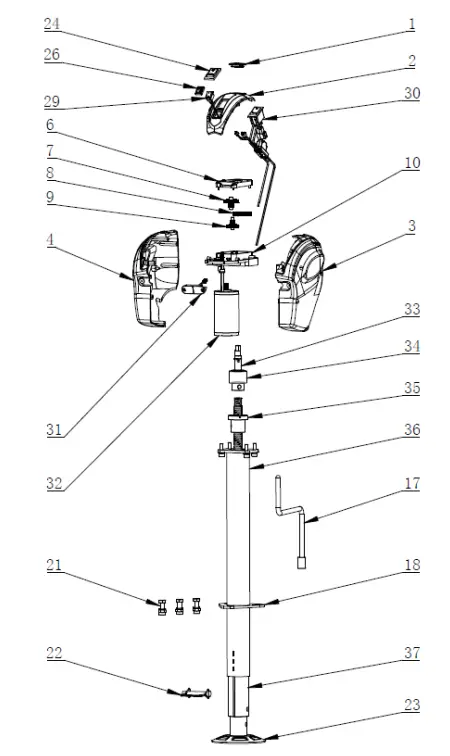
PARTS LIST
| Parts No. | Description | Qty |
| 1 | Override Protection Cover | 1 |
| 2 | Switch Cover | 1 |
| 3 | Plastic cover(right) | 1 |
| 4 | Plastic cover(left) | 1 |
| 6-10 | Gear Assembly | 1 |
| 17 | Crank | 1 |
| 18 | Mounting Plate | 1 |
| 21 | Hardware Kit | 3 |
| 22 | Lock Pin | 1 |
| 23 | Drop Leg | 1 |
| 24 | Up/Down Switch Cover | 1 |
| 26 | LED Switch Cover | 1 |
| 29 | LED Light Switch | 1 |
| 30 | Integrated Circuit Board with Up/Down Switch and Positive Wire in Black and Negative Wire in White, and 20A In Line Fuse | 1 |
| 31 | LED Light | 1 |
| 32 | Motor | 1 |
| 33 | Drive Shaft | 1 |
| 34 | Brake mechanism | 1 |
| 35 | Ball screw | 1 |
| 36 | Outer Tube | 1 |
| 37 | Inner Tube | 1 |
Limited 1 year Warranty
We make every effort to assure that this product meets high quality and durability standards, and warrants to the original purchaser that this product is free from defects in materials and workmanship for the period of one years from the date of manufacture, provided that installation and use of the product is in accordance with product instructions.
This warranty does not apply to damage due directly or indirectly, to misuse, abuse, negligence or accidents, repairs or alterations outside our facilities, criminal activity, improper installation, normal wear and tear, or to lack of maintenance. We shall in no event be liable for death, injuries to persons or property, or for incidental, contingent, special or consequential damages arising from the use of our product. Some states do not allow the exclusion or limitation of incidental or consequential damages, so the above limitation of exclusion may not apply to you. THIS WARRANTY IS EXPRESSLY IN LIEU OF ALL OTHER WARRANTIES, EXPRESS OR IMPLIED, INCLUDING THE WARRANTIES OF MERCHANTABILITY AND FITNESS.