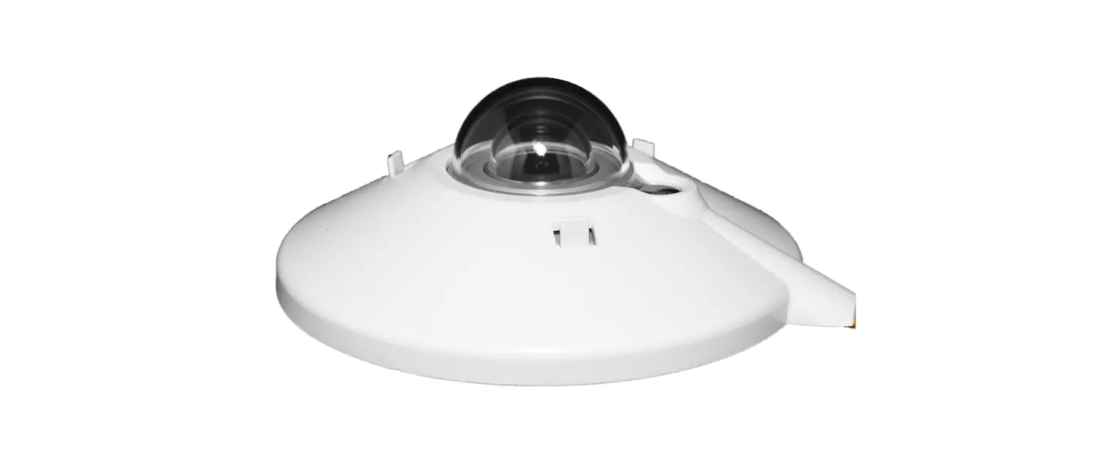
itsensor LM3485 Pyrano Meter PYRA-485 User Manual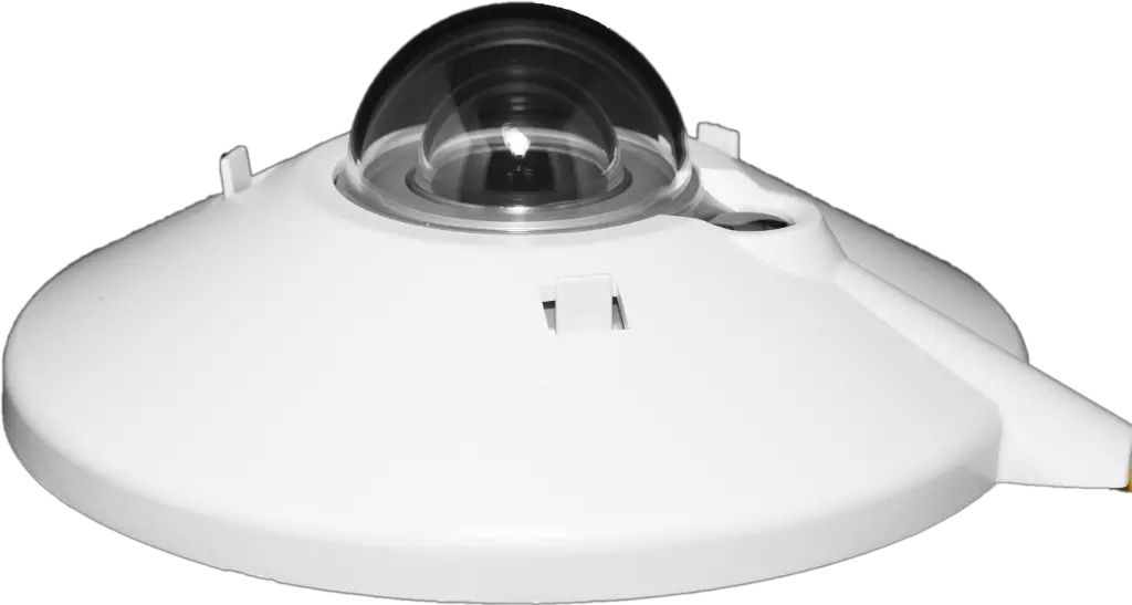
GENERAL DESCRIPTION
PYR1-485 and PYR2-485 are ISO 9060:2018 CLASS B (First Class) and CLASS C (Second Class) pyranometers respectively, with RS485 bus interface with the well known industry standard protocol Modbus RTU.
FEATURES
| PYR1-485 | PYR2-485 | |
| Measurements: spectral range input irradiance range | 300 ÷ 2900nm 0 ÷ 1600 W/m2 | |
| Response time | < 20 sec | < 25 sec |
| Temperature response | < ± 2 % (-10 to +40°C) | < ± 5 % (-10 to +40°C) |
| Zero offse Thermal radiation (at 200 W/m2 ) Temperature change (5 k/h) | <14Wm2 | <20Wm2 |
| Resolution Smallest detectable change | ||
| Outputs serial | RS485, standard Modbus RTU protocol 1W/m | |
| Output resolution: | ± 4 W/m² | ± 8 W/m² |
| Output precision Tilt response (0 ÷ 90°) Temp. Response ( ∆t = 50K) | < ± 2% < 4% | < ± 4% < 8% |
| Working temperature: | -40 ÷ +80 ° | |
| Supply | C 9 ÷ 30 Vdc protected against short circuit | |
| Encapsulation: | Quartz [k5] | |
| Special glass transparent to | Double glass dome 0,3 ÷ 3,0 μm | Single glass dom 0,3 ÷ 3,0 μm |
| Case | Anodized aluminum | |
| Connectors | standard M8 4 pin female | |
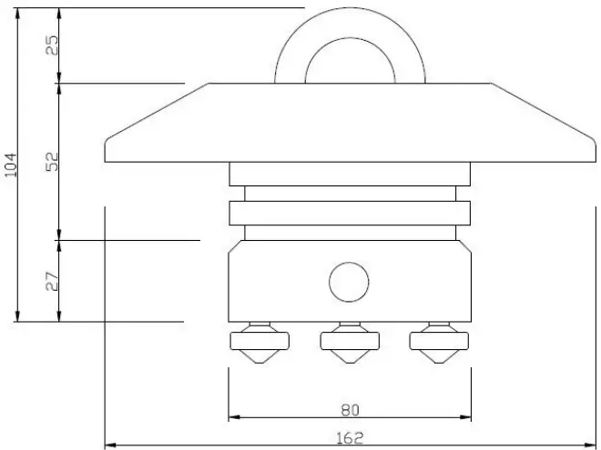
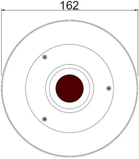
| Dimensions | Φ 162 x h 104 mm | |
PIECE’S LIST
- Pyranometer with sun screen
- M8 4pin male connector
- Instruction sheet
- Calibration Report
CALIBRATION
Date:.……………………………………….
Operator: ……………………………….
S/N:………………………………………….
Modbus Node: ………………………
DIMENSIONS
CONNECTIONS
See the table below. Once connected the irradiance values comes out instantly (Fig.1 has correspondence with the rear side where you have to connect wires)
| # pin | SolSol Cable Color | Description |
1 | Green | RS485+/B, communication bus non inverting bus signal |
2 | Red | Power supply 12 ÷ 30Vdc |
3 | Green/White | RS485-/A, communication bus inverting bus signal |
| 4 | Black | Power supply / 0 Vdc |
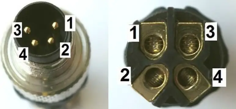
Fig.1 Front and back view of male connector
Data is accessible through Modbus’s functions by 16 bits units called “registers”. In the current implementation of PYRA-485 these registers are available:
| Register hex | Register dec | Description | Access | NV save | |||
| 0x0101 | 257 | Current irradiance level [W/m2] | R | ||||
| 0x8802 | 34818 | Current body temperature [°C], 2-complent value, fixed point 14.2 format (14 bits integer, 2 bits fractional) | R | ||||
| 0x0103 | 259 | Status, bit coded | R | ||||
| Bit | Description | ||||||
| 0 | Factory calibration/configuration 1 = OK; 0 = need recalibration | ||||||
| 1 | Not volatile parameters 1 = OK; 0 = default loaded, need to be changed/saved | ||||||
| 2 | Not used | ||||||
| 3 | Not used | ||||||
| 4 | Not used | ||||||
| 5 | Watchdog 1 = reset by watchdog timeout occurred; 0 = normal operation | ||||||
| all undefined bits read as 0 | |||||||
| 0x8001 | 32769 | Serial number, least significant word | R | ||||
| 0x8002 | 32770 | Serial number, most significant word | R | ||||
| 0x8003 | 32771 | Firmware main version, hexadecimal | R | ||||
| 0x8004 | 32772 | Firmware minor version, hexadecimal | R | ||||
| 0x8005 | 37773 | Node address, range 1 ¸ 247, decimal, default 1 | R/W | Y | |||
| 0x8006 | 32774 | Bitrate, coded, range 0 ¸ 4, decimal, default 1 0 – 9600 bps | R/W | Y | |||
| 0x8007 | 32775 | Serial configuration, coded, range 0 ¸ 3, decimal, default 0 0 – 8N1 (8 bit / no parity / 1 stop bit) | R/W | Y | |||
| 0x8008 | 32776 | Serial reply delay [ms], range 0 ¸ 100, decimal, default 1 | R/W | Y | |||
| 0x8101 | 33025 | Not volatile params save command, write 1 to execute (then wait 1 s before to send next message) | W | ||||
| 0x8102 | 33026 | Software reset command, write 1 to execute (then wait 6 s before to send next message) | W | ||||
CALIBRATION
It is recommended to send to factory for verifying calibration after 2 years of outdoor work
MAINTENANCE
Reading is reduced if the dome is not clean.
- Keep the dome clean using water or alcohol.
- Keep instrument levelled.
- Recalibrate every 2 years.
INSTALLATION
It is recommended to install the product at a minimum height of 180cm above the ground.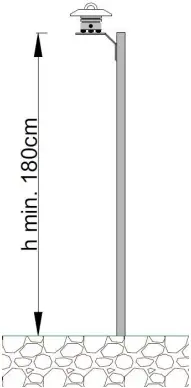
There are the following fixing types:
- With M5 screw on flat bases;
- Bracket on pole;
- Inclinable bracket in degrees
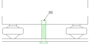
M5 screw on flat bases *screw’s thread must be 0,4cm + distance between the pyranometer and the base. (approx. 1,5 – 1,8 cm long.)
USER INFORMATION
Read this document carefully before installation.
Warranty is 2 years from date of invoice, subject to correct installation and use. Soluzione Solare accepts no liability for any loss or damage arising from incorrect use of the product. This device conforms to the EU ‘CE’ guideline 89/336/EEC73/23/EEC. Unauthorised modifications may void the warranty and CE validity. Visit our website for the latest product support information.
CONTACTS
For further information, contact us:
[email protected]
+39 0425 1810834
ITSENSOR Srl– Viale Porta Adige 45 – Torre Uffici Censer – 45100 Rovigo (RO) – ITALY
www.itsensor.it
+39 0425 1810834
[email protected]


