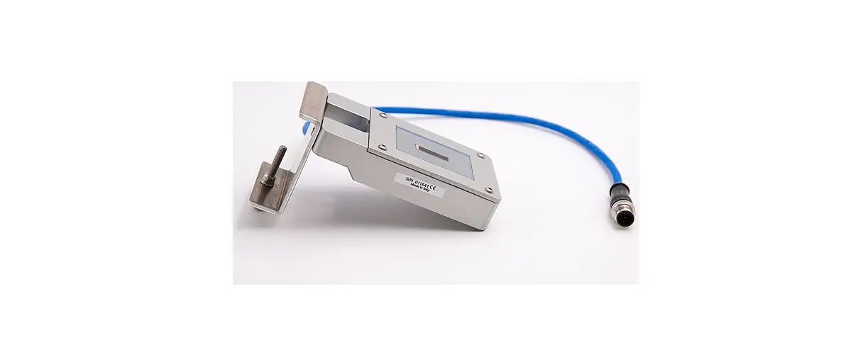
itsensor LM2-485 Pro Digital Photovoltaic Pyranometer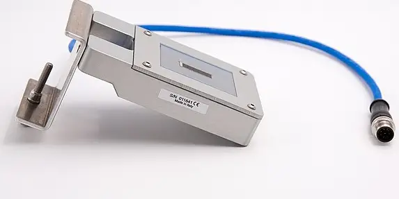
GENERAL DESCRIPTION
The LITEMETER LM2-485 is a solar irradiation sensor with strictly selected electronic components to ensure maximum precision also along temperature changes. This sensor has RS485 bus interface with the well known industry standard protocol Modbus RTU.
FEATURES
- Measurements: irradiation range:
- Outputs serial: 0 ¸ 1250 W/m2
- Output resolution: RS485, standard Modbus RTU protocol 1W/m2
- Output precision: irradiation: cell temperature
- Non-stability: ± 5% (2.5% @S.T.C. (25°C)) ± 1°C
- Non-linearity (0 to 1000 W/m2): <3% year ≤0.5% (@S.T.C. (25°C))
- Working temperature:-30 ¸ +85 °C
- Supply: 12 to 30Vdc (see scheme on page 2)
- Power consumption maximum:85mW
- Encapsulation: small microprismatic glass for photovoltaic modules and E.V.A
- Case: aluminium with stainless steel with screw-clamp to fix it on modules or montage profile
- Wiring: 3 m cable UV resistant with 4 wires 0,25mm2
- Connectors: free pins (4 + 1 GND)
- Dimensions: 55 x 99 x 24 mm, with mounting bracket 70 x 119 x 75 mm (overall)
PIECE’S LIST
- Instrument with cable
- Aluminium fastening clamp
- Mounting screw for the fastening clamp
- Fixing screw fastening clamp-profile/modules
Important :
the case present a hole with a diameter of a few mm, this hole is terminated by a transpiring membrane whose purpose is the barometric compensation to avoid condensation.
DON’T PERFORATE. WARRANTY VOID IF REMOVED OR PERFORATED.
MECHANICAL FASTENING
insert the solar sensor with its fastening clamp to the choosen frame of a PV module representative of the PV installation as shown in figure 2. Screw the below bolt of clamp with a wrench until it appear stable.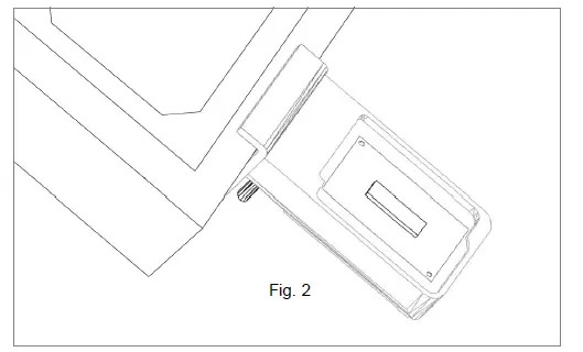
CONNECTIONS
See table1 below. Once connected the irradiation values comes out instantly
| # | Cable & TIP colour | Description |
| 1 | Red-White TIP | Power supply +12 ÷ 30Vdc |
| 2 | Black–White TIP | Power supply / Signal 0 Vdc |
| 3 | Green-White TIP | RS485+/B, communication bus non inverting signal |
| 4 | White-White TIP | RS485-/A, communication bus inverting bus signal |
| 5 | Black–Blue TIP | GND Ground |
Cabling:
to get optimum sliding of the cable in wiring, we highly recommend use of sliding products.
Data is accessible through Modbus’s functions by 16 bits units called “registers”. In the current implementation of LM2-485 are available these registers:
| Register hex | Register dec | Description | Acc ess | NV save | ||
| 0x0101 | 257 | Current irradiation level [W/m2], range 0 ¸ 1250, decimal | R | |||
| 0x8802 | 34818 | Current cell temperature [°C], range –30 ¸ +90, 2-complent value, fixed point 14.2 format (14 bits integer, 2 bits fractional) | R | |||
| 0x0103 | 259 | Status, bit coded | R | |||
| Bit | Description | |||||
| 0 | Factory calibration/configuration 1 = OK; 0 = need recalibration | |||||
| 1 | Not volatile parameters 1 = OK; 0 = default loaded, need to be changed/saved | |||||
| 2 | Not used | |||||
| 3 | Not used | |||||
| 4 | Not used | |||||
| 5 | Watchdog 1 = reset by watchdog timeout occurred; 0 = normal operation | |||||
| all undefined bits read as 0 | ||||||
| 0x8001 | 32769 | Serial number, least significant word | R | |||
| 0x8002 | 32770 | Serial number, most significant word | R | |||
| 0x8003 | 32771 | Firmware main version, hexadecimal | R | |||
| 0x8004 | 32772 | Firmware minor version, hexadecimal | R | |||
| 0x8005 | 37773 | Node address, range 1 ¸ 247, decimal, default 60 | R/ W | Y | ||
| 0x8006 | 32774 | Bitrate, coded, range 0 ¸ 4, decimal, default 1 0 – 9600 bps | R/ W | Y | ||
| 1 – 19200 bps 2 – 38400 bps 3 – 57600 bps 4 – 115200 bps | ||||
| 0x8007 | 32775 | Serial configuration, coded, range 0 ¸ 3, decimal, default 0 0 – 8N1 (8 bit / no parity / 1 stop bit) 1 – 8E1 (8 bit / even parity / 1 stop bit) 2 – 8O1 (8 bit / odd parity / 1 stop bit) 3 – 8N2 (8 bit / no parity / 2 stop bit) | R/ W | Y |
| 0x8008 | 32776 | Serial reply delay [ms], range 0 ¸ 100, decimal, default 1 | R/ W | Y |
| 0x8101 | 33025 | Not volatile params save command, write 1 to execute (then wait 1 s before to send next message) | W | |
| 0x8102 | 33026 | Software reset command, write 1 to execute (then wait 6 s before to send next message) | W |
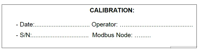
CALIBRATION
It is recommended to send to factory for verify calibration after 2 years of outdoor work.Some “inclusions” may be present and clearly visible into the protective encapsulation resin. This is due to the resin coating process and do not affect overall performance and/or accuracy.


