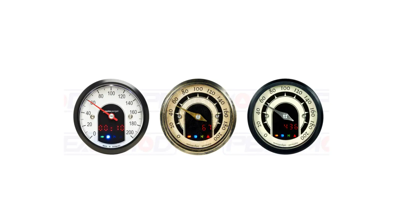
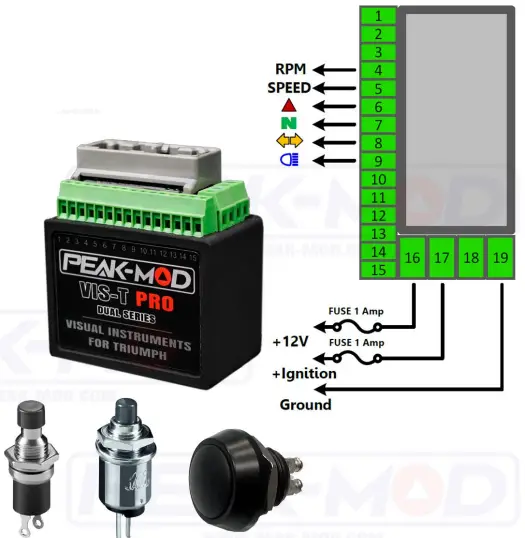
PEAK-MOD VIS-T Pro Visual Instrument for Triumph User Manual
From motoscope pro user manual


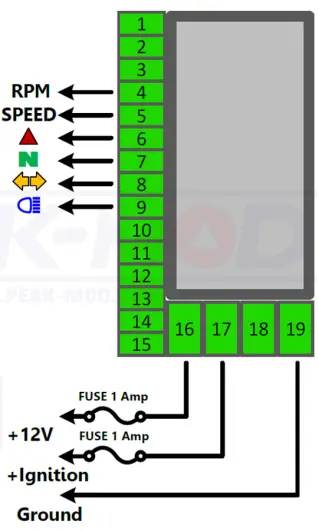
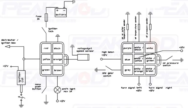
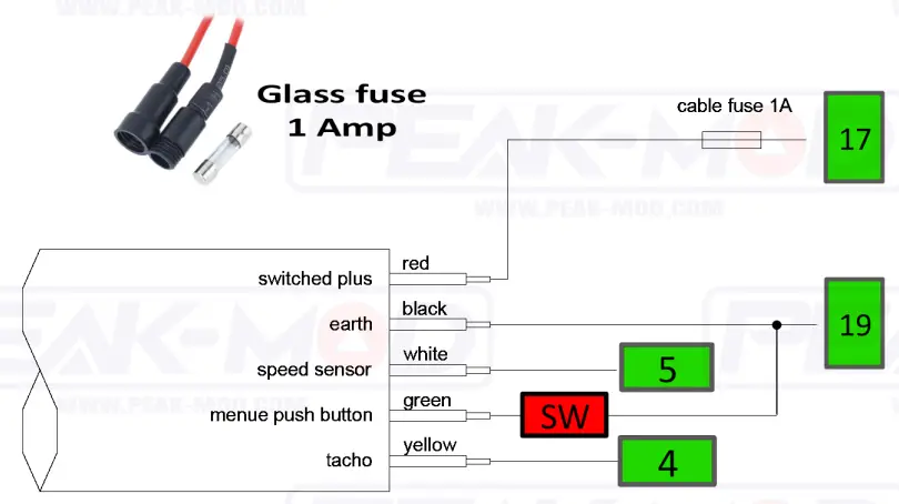
Connection Scheme
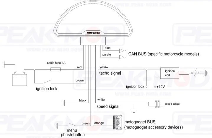
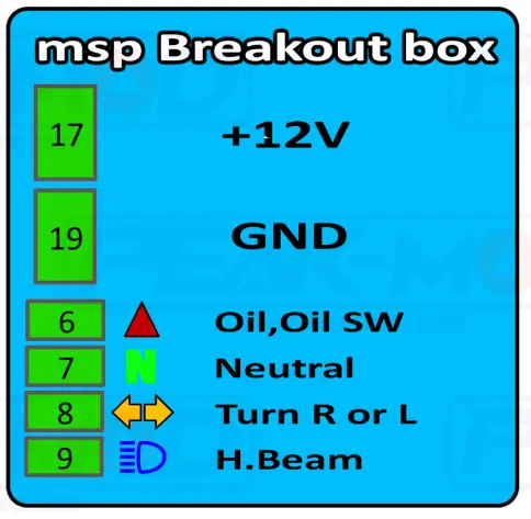
Power Connectors
- +12 Volt form Battery. (Connected directly to +battery. Please carefully.
- +12 Volt form ignition key.
- Signal form internal flasher relay (Internal connected to OEM turn switch.)
- Ground (-)
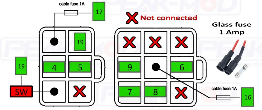
Cautious
Power connectors 16 & 17 currents not exceed 1 amp.
Please install glass fuse for protection internal break circuit.
Note. All output 4 to 15 max currents at 0.02Amps per channel.
For mortoscope pro Goto param menu
- CIRC set to 2000
- Impw set to 1
- Impe set to 1

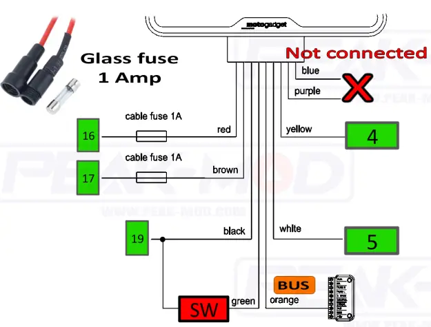
![]()
![]() Connect to external momentary switch. For control motoscope pro itself.
Connect to external momentary switch. For control motoscope pro itself.
DO NOT CONNECT TO ![]()
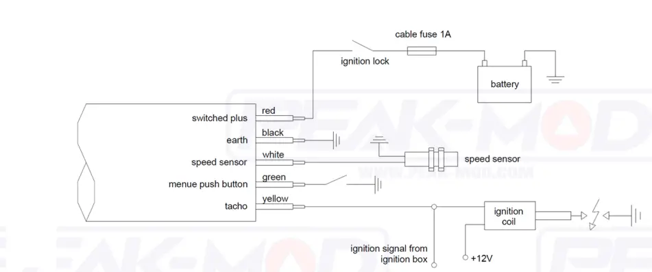
From motoscope tiny user manual
Connection Scheme
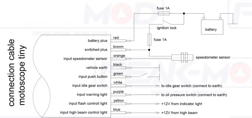
Power Connectors
- +12 Volt form Battery. (Connected directly to +battery. Please carefully.
- +12 Volt form ignition key.
- Signal form internal flasher relay (Internal connected to OEM turn switch.)
- Ground (-)
Cautious
Power connectors 16 & 17 currents not exceed 1 amp.
Please install glass fuse for protection internal break circuit.
Note. All output 4 to 15 max currents at 0.02Amps per channel.
For mortoscope tiny Goto param menu
- menu 3 (set PULSE) set to 1
- menu 4 (set CIRC) set to 2000
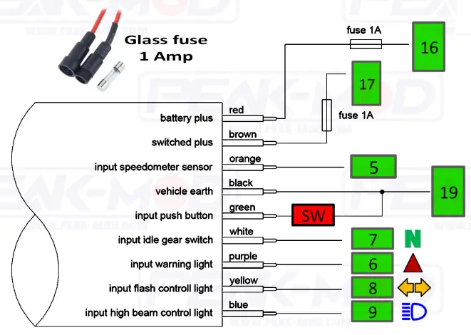

![]()
![]() Connect to external momentary switch. For control motoscope tiny itself.
Connect to external momentary switch. For control motoscope tiny itself.
DO NOT CONNECT TO ![]()
From motoscope classic user manual

Connection Scheme

Power Connectors
- +12 Volt form Battery. (Connected directly to +battery. Please carefully.
- +12 Volt form ignition key.
- Signal form internal flasher relay (Internal connected to OEM turn switch.)
- Ground (-)
Cautious
Power connectors 16 & 17 currents not exceed 1 amp.
Please install glass fuse for protection internal break circuit.
Note. All output 4 to 15 max currents at 0.02 Amps per channel.
For mortoscope classic Goto param menu
- WHLSIZE set to 2000
- Impwhl set to 1
- Impeng set to 1
![]()
![]() Connect to external momentary switch. For control motoscope classic itself.
Connect to external momentary switch. For control motoscope classic itself.
DO NOT CONNECT TO ![]()
From motoscope mini user manual

Connection Scheme
Power Connectors
- +12 Volt form Battery. (Connected directly to +battery. Please carefully.
- +12 Volt form ignition key.
- Signal form internal flasher relay (Internal connected to OEM turn switch.)
- Ground (-)
Cautious
Power connectors 16 & 17 currents not exceed 1 amp.
Please install glass fuse for protection internal break circuit.
Note. All output 4 to 15 max currents at 0.02Amps per channel.
For mortoscope mint Goto param menu
- CIRC set to 2000
- Impw set to 1
- Impe set to 1

![]()
![]() Connect to external momentary switch. For control motoscope mini itself.
Connect to external momentary switch. For control motoscope mini itself.
DO NOT CONNECT TO ![]()


