![]() Cap-Can Monitoring System
Cap-Can Monitoring System
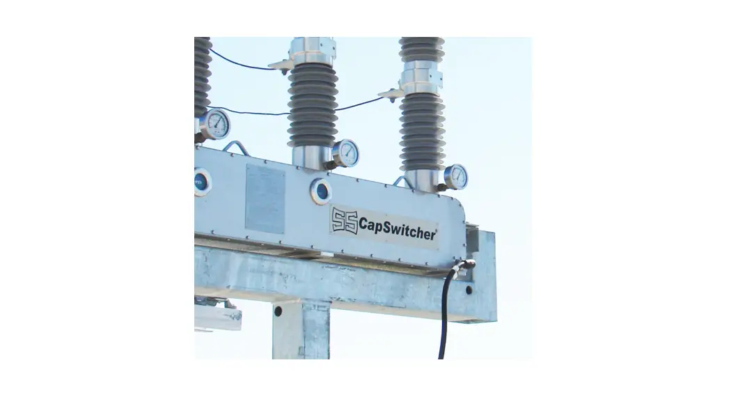
General Description The capacitor monitoring system is comprised of two main components, the cap-can sensor, and the receiver. The cap-can sensor performs the majority of the “heavy lifting” by continuously sampling the voltage across and the current flowing through the capacitor. It then computes the impedance in order to provide an indication for the health of the cap-can. Some of this data is transmitted via on-request RF to the receiver. The receiver then in turn can transmit the data to any other systems for storage or display purposes. Ultimately, the sensor performs all of the capacitor health detections and the receiver allows for remote monitoring. 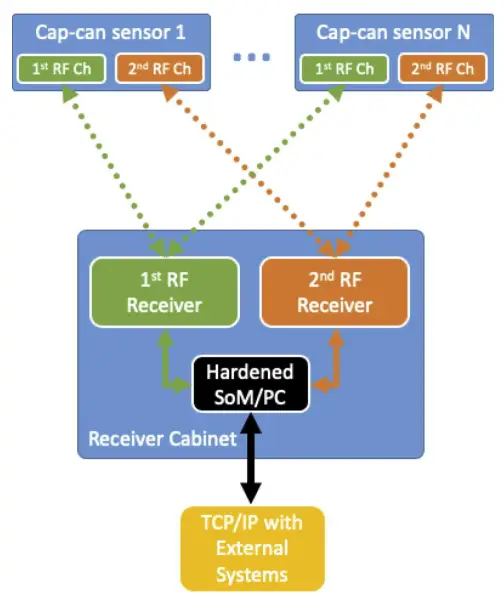
Failure Detection Scheme
The sensor continuously monitors the voltage and current across the can to compute the can impedance. Based on preset trigger impedance levels of “warning” and “failure”, the sensor will illuminate the LED as well as send out the data via the 2″ RF Ch to notify the receiver that a “warning” or “failure” has been detected. The notification via the 2″ RF Ch is necessary in cases where the cap-can failure causes the capacitor bank protection relay to trip off the entire bank. The receiver will receive the notification prior to the bank turning off and thereby the proper personnel can find the failed cap-can even if the bank is de-energized.
Cap-Can Sensor Specifications
| Specification | Value |
| Capacitor Can Type | Fuseless |
| System Voltage | 345 kV |
| Capacitor Voltage | 25 kV |
| Capacitor Current | 175 A |
| Operating Temperature | -20C – 65C |
| RF Modules | 1 |
| RF Frequency | 2.4 GHZ |
| RF Channels | 255 |
| RF Module Operating Mode | Transmit & Receive |
| Measurements | RMS Voltage, RMS Current |
Cap-Can Receiver Specifications
| Specification | Value |
| Input Power Voltage | 120VAC |
| Operating Temperature | -20C – 65C |
| Cabinet Material | Polycarbonate NEMA4 |
| RF Modules | 2 |
| RF Frequency | 2.4 GHZ |
| RF Channels | 255 |
| 1st RF Module Operating Mode | Transmit & Receive |
| 2″ RF Module Operating Mode | Receive |
| SoM/PC OS | Linux |
Notices
Warning: Changes or modifications not expressly approved by the party responsible for compliance could void the user’s authority to operate the equipment.
NOTE: This equipment has been tested and found to comply with the limits for a Class B digital device. pursuant to Part 15 of the FCC Rules. These limits are designed to provide reasonable protection against harmful interference in a residential installation. This equipment generates. uses. and can radiate radio frequency energy and. if not installed and used in accordance with the instructions. may cause harmful interference to radio communications. However, there is no guarantee that interference will not occur in a particular installation. If this equipment does cause harmful interference to radio or television reception, which can be determined by turning the equipment off and on. the user is encouraged to try to correct the interference by one or more of the following measures:
- Reorient or relocate the receiving antenna.
- Increase the separation between the equipment and receiver.
- Connect the equipment into an outlet on a circuit different from that to which the receiver is connected.
- Consult the dealer or an experienced radio/TV technician for help.
This equipment complies with radiation exposure limits set forth for an uncontrolled environment. This equipment should be installed and operated with a minimum distance of 20 cm’ between the radiator and your body. This transmitter must not be co-located or operating in conjunction with any other antenna or transmitter.


