 TRU-BOLT 0711016 ELECTRONIC DEADBOLT KEYPAD User Manual
INSTALLATION INSTRUCTIONS
ELECTRONIC DEADBOLT WITH KEYPAD
Do NOT use an electric screwdriver, only hand-tighten screws with Phillips head screwdriver. DO NOT OVER-TIGHTEN SCREWS.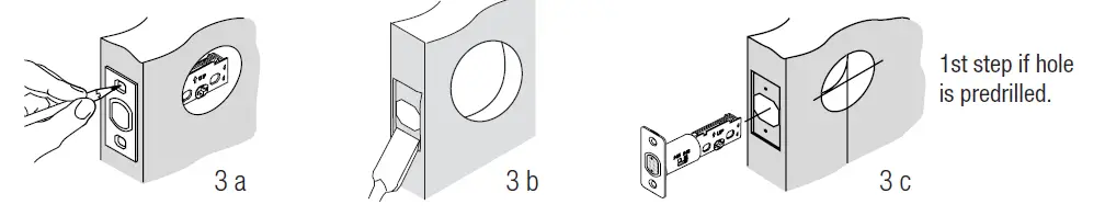
Please read and understand this entire manual before attempting to assemble, operate or install the product.
- MARK DOOR FOR DRILLING

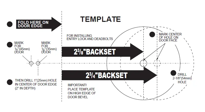
Note: If your door has pre-drilled holes skip to step 3 C Start 36” from floor. Fold and apply template (page 17) to high edge of door. Mark center hole on door face through guide on template for 2-3/8” (60 mm) or 2-3/4” (70 mm) backset. - DRILLING HOLES
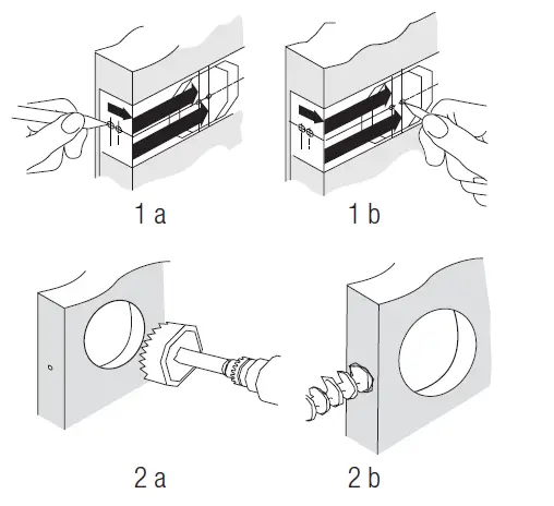
Drill 2-1/8” hole through door face as marked for lock set. Drill 1” hole in center of door edge for latch. - MARKING THE JAMB HOLE LOCATION
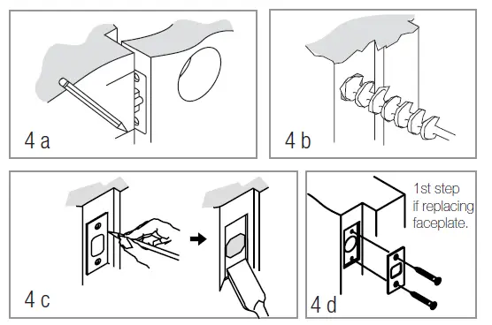
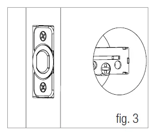
Chisel 1/8” deep or until latch face is flush with door edge. Insert latch and tighten screws. - INSTALL DEADBOLT STRIKE PLATE
Mark template from edge of jamb and locate strike opening. Drill 1” hole 1 3/16” deep in door jamb on center line of screws. Outline outside edges of strike. Chisel 1/6” deep for strike or until flush. Install strike and tighten screws (A).
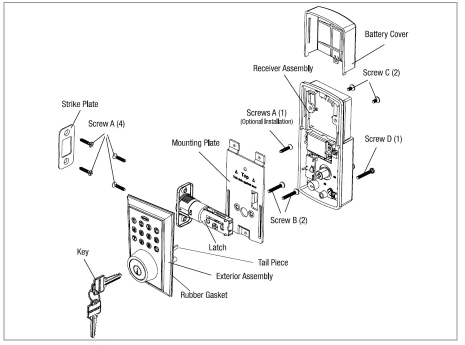
INSTALLATION OVERVIEW
For troubleshooting tips and “how to videos” visit www.truboltlocks.info
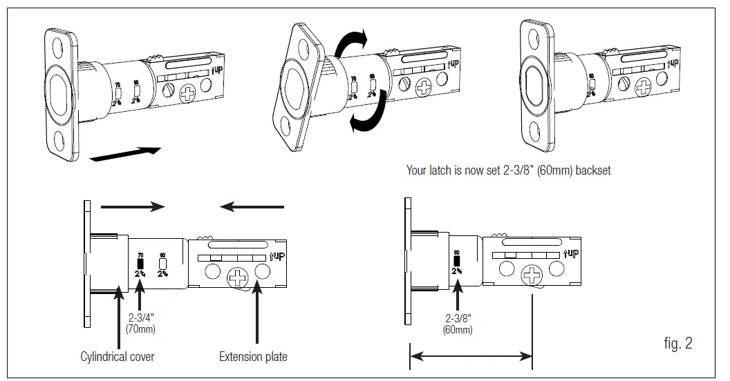
- ADJUSTING THE DEADBOLT LATCH BACKSET (Deadbolt is shipped with the backse To convert from 2-3/8” (60mm) backset to 2-3/4” (70 mm) backset
- Hold latch with numbers facing forward and thumb pressing on the bolt
- Rotate the cylinder cover Clockwise
- Pull and twist the extension plate all the way out
- Rotate the cylinder cover counter-clockwise so that the marking aligns with the 2-3/4” position indicator
NOTE: Do not extend Cylindrical Cover past 2-3/4”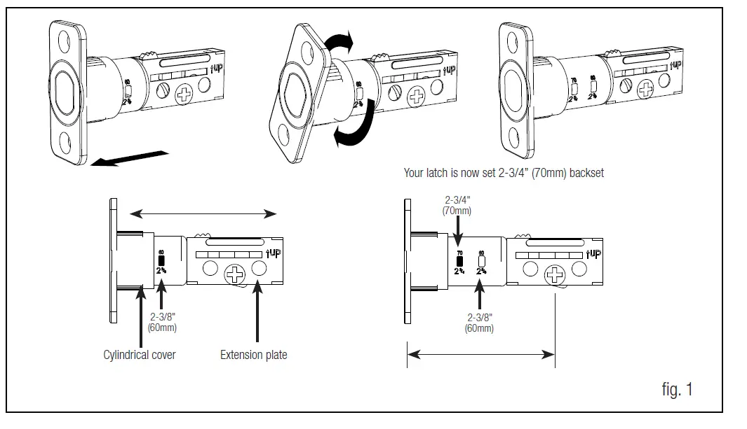
TO CONVERT FROM 2-3/4” (70 MM) BACKSET TO 2-3/8” (60MM) BACKSET
- Hold latch with numbers facing forward and thumb pressing on the bolt
- Rotate the cylinder cover Clockwise
- Push and twist the extension plate all the way in
- Rotate the cylinder cover counterclockwise so that the marking aligns with the – 3/8” position indicator

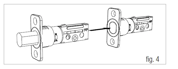
INSTALLING THE DEADBOLT LATCH (need Phillips head screwdriver)
- Insert Deadbolt Latch into door edge hole with the word UP and the arrow on the extension plate facing UP. A cross-shaped spindle connector will be at the bottom of the Deadbolt Latch.
- Make sure the face plate sits flush with the door. Do not force the latch into the mortise flush. Chisel out excess mat

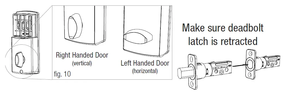
Deadbolt Latch must be retracted when installing
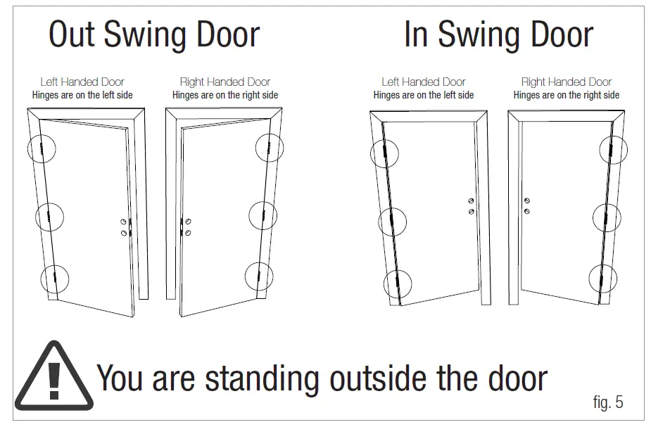
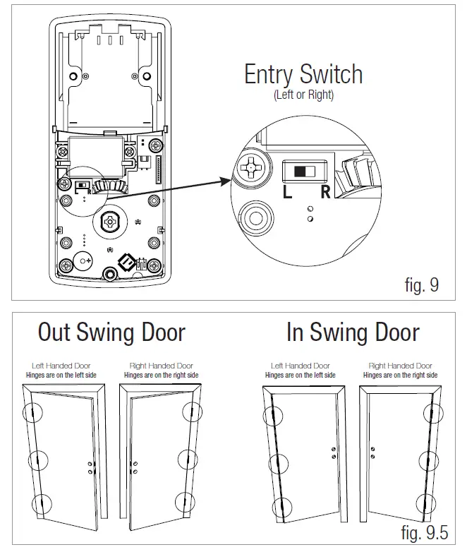
IDENTIFYING YOUR DOOR HANDING’
- If the hinges are on the left your door is Left Handed
- If the hinges are on the right your door is Right Handed

INSTALLING THE EXTERIOR ASSEMBLY
Work with the Door Open for easy access
- Unpack the Exterior Assembly. Use care to not scratch the green circuit board during handling and installation.
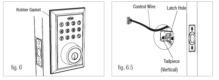
- Check that the rubber gasket is properly seated on the Exterior Assembly. ( see figure 6 )
- Insert the Exterior Assembly onto the door with the tailpiece going through the Deadbolt Latch cross-shaped spindle connector in the VERTICAL POSITION. Route the Control Wire through the door below the Deadbolt Latch. (see figure 6)
NOTE: TAILPIECE MUST BE POSITIONED VERTICALLY
- NOTE: Unpack the Interior Assembly. Remove the battery cover by sliding the cover upward. Locate the one screw holding the Mounting Plate to the Interior Assembly. Remove the screw to release the Mounting Plate from the Interior Assembly.
SECURING THE EXTERIOR ASSEMBLY TO THE DOOR
- From the side marked “This side against door”, route the Control Wire through the rectangular slot in the Mounting Plate
- Place Mounting Plate against door with tailpiece passing through the center hole in the three hole set
- Secure the Mounting Plate to the Exterior Assembly using Screw B (2 ea)
- Hand tighten with a screwdriver leaving loosely connected
- Check that the Rubber Gasket is properly aligned and correct as necessary.
- Check vertical alignment of the lock
- Tighten with a hand held screwdriver. DO NOT OVER TIGHTEN

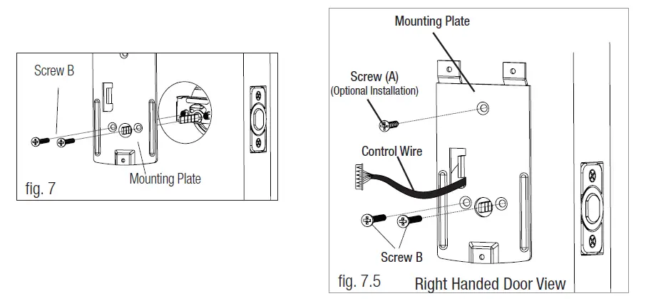
OPTIONAL INSTALLATION
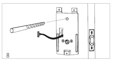
- Using a 1/16” drill bit, drill a pilot hole in your door using the Mounting Plate upper hole as a guide (see Figure 8a)
- Insert Screw A and tighten

NOTE: LOCK AND UNLOCK USING THE KEY TO SEE IF THE DEADBOLT LATCH IS OPENING AND CLOSING EASILY.
INSTALLING THE INTERIOR ASSEMBLY
- Set the Entry Switch for Left or Right Handed door
- Gently move the switch to “L” for Left Handed Door
- Gently move the Switch to “R” for Right Handed Door

SET THE INTERIOR KNOB POSITION FOR LEFT OR RIGHT-HANDED DOORS
- The knob goes in the VERTICAL position for Right Handed Doors
- The knob goes in the HORIZONTAL position for Left Handed Doors

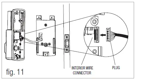
ATTACH THE CONTROL WIRE TO THE INTERIOR ASSEMBLY
- Use care to attach the Control Wire to the interior Wire Connector.
- Do not force Plug onto Wire Connector.
- The Plug has two alignment tabs on the smooth side of the Wire Connector.
- The Plug is inserted with the smooth side facing left into the Wire Connector and pressed into place.

- Position the Interior Assembly over the tailpiece and push the Interior Assembly against the door
- Using Screw C (2 ea) and Screw D (1 ea), attach the Interior Assembly to the Mounting DO NOT OVER-TIGHTEN SCREWS

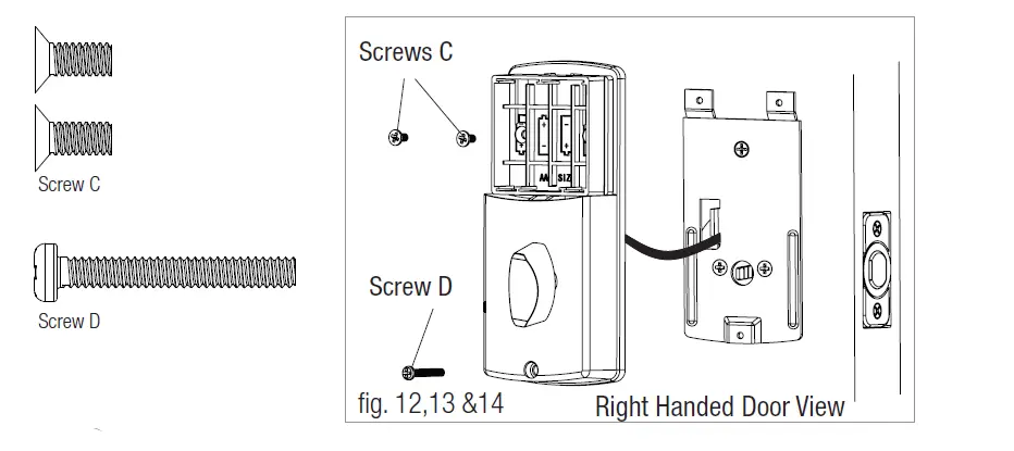
NOTE: LOCK AND UNLOCK USING A THUMB-TURN KNOB TO SEE IF THE LATCH IS OPENING AND CLOSING EASILY.
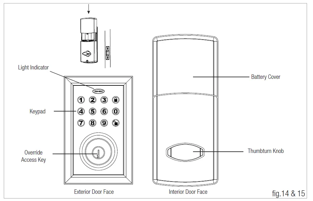
BATTERY INSTALLATION
- Insert 4 AA high-quality Alkaline batteries into the Battery Compartment in the direction noted +/- on the Compartment. The Lock will beep 2 times, the Keypad will illuminate blue, and the Tru-Bolt button will flash green twice to signify that it has received power.NOTE: DO NOT touch the keypad until the blue light turns off. DO NOT use rechargeable batteries or non-alkaline batteries.
- Slide the Battery Cover down into the track on the Interior Assembly to cover the batteries

With the Door Open
Test the Lock using the interior turn piece, bolt should move smoothly
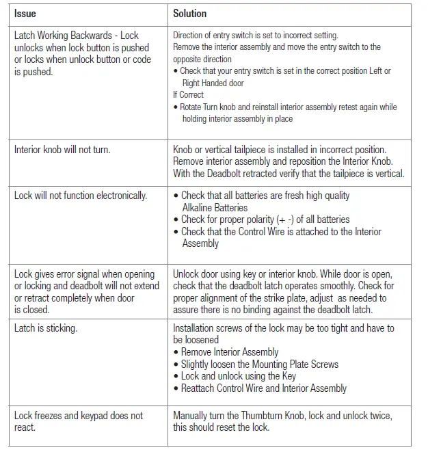
Trouble Shooting
Go to the Programming Directions to set your personal codes and make your lock secure.
PROGRAMMING AND O PERA TING INSTRUCTIONS
Batteries (not included)
Electronic lock requires (4) High-Quality AA Alkaline batteries. When all 4 batteries are installed in the correct position, hear 2 beeps and the keypad will illuminate blue.
Locking and Unlocking
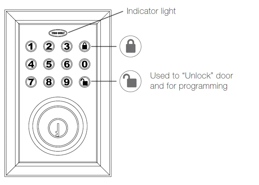
- TO UNLOCK THE LOCK
Using Keypad: Enter a valid User Code (default code is 1234) and press 1 beep and light green.
Basic Functions
DELETE ALL USER CODES (Make sure the latch is extended)
IMPORTANT: This will delete the user codes but not the programming code, enter the following:
Hear 1 beep and Light Indicator illuminates green
TO ADD A NEW USER CODE (you can add up to 50 new user code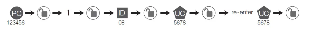
The User Code UC must be a 4-8 digit combination. Each User Code UC is then (which is any number between 01-50) to identify an individual For example: to add the User ID – 5678, enter the following:
Hear 1 beep and Light Indicator illuminates green
NOTE: When a NEW USER CODE is set, the default factory code (1234) is deleted for safety.The unit comes with a factory User ID ID IMPORTANT: To delete 1 User Code UC , the lock must have more than 1 in its database.
Hear 1 beep and Light Indicator illuminates green
Advanced Functions
CHANGE CURRENT OR PRESET PROGRAMMING CODE Factory default Programming Code PC = 123456, this is the master password for your lock. All programming functions require this code. Follow the below sequence to change the to your custom 6 digit combination. Hear 1 beep and Light Indicator illuminates green
To cancel Auto Lock set the time to 00, enter the following:
Cancel Time Value Auto Lock: PC 5 Hear 1 beep and Light Indicator illuminates green
TEMPORARILY DISABLE AUTO LOCK
Disable: While in Auto-Lock mode, unlock door using PC , within 10 seconds you must turn the locking knob by hand to the locked position, wait more than 2 seconds then turn the locking knob back to the unlock position. The Auto-Lock mode is now disabled.Restore: To restore the Auto-Lock function, you can turn the locking knob by hand to the locked position, wait more than 2 seconds or press the Lock button on the keypad.
TURN ON AND OFF SOUND
You can “mute” or turn the “sound on” on your lock by entering the following. (Factory setting is sound on)
Sound Off (1) – Light Indicator illuminates green
Sound On (2) – Hear 1 beep and Light Indicator illuminates green
CREATE A TEMPORARY CODE
Temporary access for house sitter, contractor, cleaning company, etc. Use one of the 50 available User Codes UC and give it out for temporary access and delete it when it is no longer required. See steps 3 and 4 on page 13.
VACATION MODE
With Vacation Mode enabled, the system enters into low-power consumption mode. During this mode, all buttons and functions including the remote control will be invalid until they are re-enabled (see steps below).
Enable: PC 10 1
Hear 1 beep and Light Indicator illuminates green then lock the door
Disable:Audio and Visual Message Guide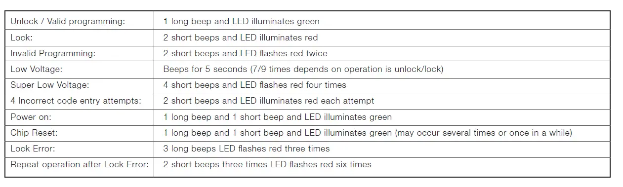
Attention:
When battery is under low voltage, the lock will give the (Low Battery Warning: Beeps and LED ashes red for 5 seconds). During this time your lock can still work. However once the voltage is lower than 4.3V (called Super-Low Voltage), the operation of the locking and unlocking will not work, user must replace batteries immediately.
Limited 1-Year Electronic Warranty
Limited Lifetime Mechanical and Finish Warranty
This Tru-Bolt® product comes with a 1-Year Limited Warranty on Electronic Parts and a Limited Lifetime Mechanical and Finish Warranty against defects in materials and workmanship under normal use to the original residential user. Simply bring this product with the original sales receipt back to your nearest MENARDS® retail store. At its discretion, Tru-Bolt® agrees to have the product or any defective part[s] repaired or replaced with the same or similar Tru-Bolt® product or part[s] free of charge. This warranty is nontransferable, and applies to the original purchaser only, as long as the original purchaser occupies the residential premises upon which the product[s] was originally installed. Proof of purchase and ownership is required for the warranty to be in effect. Requests for credit for defective item[s] must be made to any Menards® retail store. This warranty DOES NOT COVER removal and reinstallation of product[s], scratches, abrasions, deterioration due to the use of paints, solvents or other chemicals, abuse, misuse, or product[s] used in commercial applications, does not cover any losses, injuries to persons/property or costs, and shipping and freight expenses required to return product[s] to nearest Menards® retail store. In no event shall Tru-Bolt® be liable for any special, incidental or consequential damages. Customers will receive instructions as to the disposition of the defective item[s]. Menards® reserves the rights, which may vary from state to state. If this product[s] is considered a consumer product, please be advised that some local and state laws do not allow limitations on incidental or consequential damages or how long an implied warranty lasts, so that the above limitations may not fully apply. Refer to your local laws for your specific rights under this warranty.
Package Warranty:
Limited Lifetime Mechanical & Finish Warranty: This Tru-Bolt® product[s] comes with a 1-Year Limited Warranty on Electronic Parts and a Limited Lifetime Mechanical and Finish Warranty against defects in materials and workmanship under normal use to the original residential user. Simply bring this product[s] with the original sales receipt back to your nearest MENARDS® retail store and we’ll replace it with the same or similar Tru-Bolt® product or part. See installation instructions for full terms and conditions.
My Codes