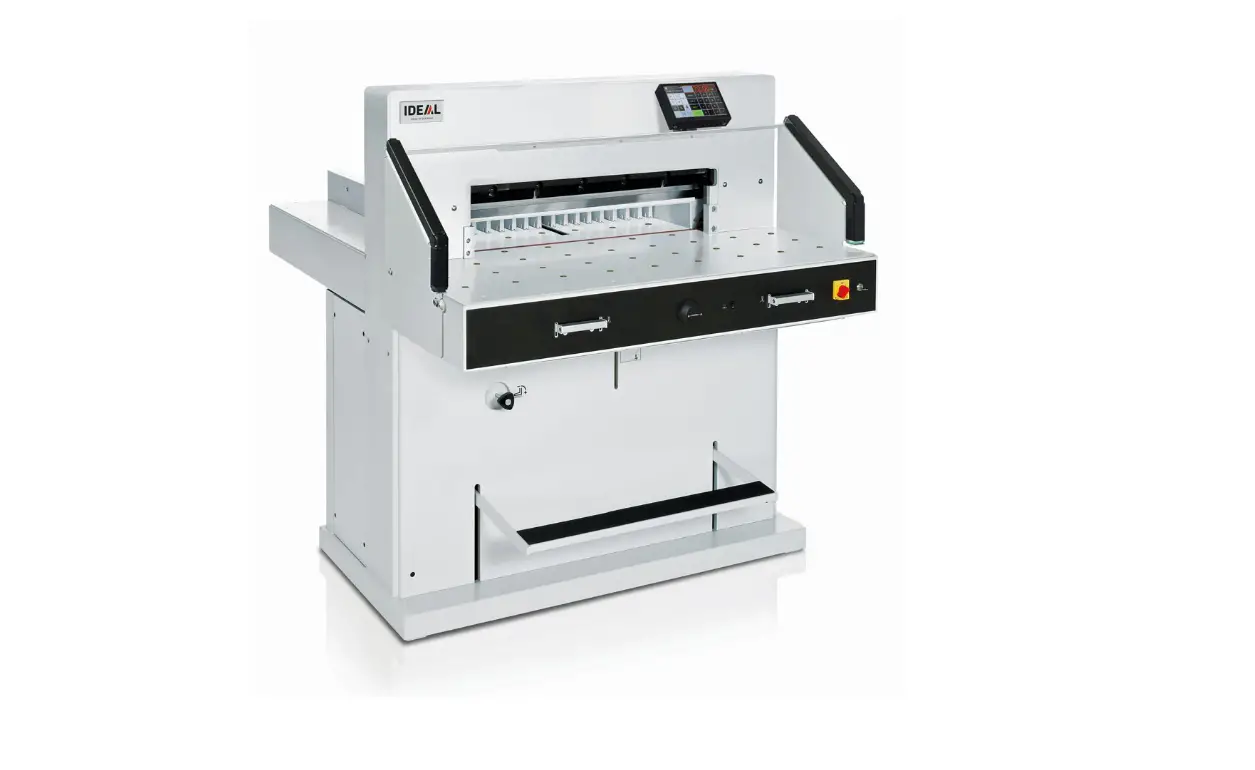
EBA 7260 Electric Guillotine
Guillotines
EBA 7260
EN Operating Instructions
www.eba.de
Table of Contents
Safety precautions
3
Intended use
4
Installation
9
Startup
10
Operation
13
Operating elements
16
Blade and cutting stick replacement
24
Maintenance and cleaning
33
Annual inspection / Safety test
35
Possible malfunctions
36
Accessories
43
Technical data
44
EC-declaration of conformity
47
– 2 –
Safety precautions Please read these operating instructions before putting the machine into operation and observe the safety precautions. The operating instructions must always be available.
Children must not operate the machine!
Do not reach beneath the blade!
Never leave the blade unattended! Do not extract or transport the blade without protection! (See page 27 and 29).
Danger! Risk of injury!
Do not cut hard materials or materials which may splinter!
– 3 –
Safety precautions / Intended use
Do not use any spray cans with flammable content near to the cutting machine!
Do not use any flammable cleaning agents.
Intended use
The machine is designed for cutting stacks of paper to a specified size. This machine is constructed for “one-man operation” only!
Warning! Clips or similar damage the cutting blade.
– 4 –
Safety precautions
Disconnect from the mains before starting any service work or before removing the panels!
Replacement of blade and cutting stick may be performed only when the main switch is switched off!
– 5 –
Safety precautions
A
A
B
All components which may endanger the operator are covered by a guard (A).
Do not operate the machine without the following safety devices: · Panels, tightly screwed (A). · Safety beam guard (B).
B
A
D
The cutting action, which is dangerous to the operator, is protected by a two-handed control
system (C) and safety beam guard (D).
C D
– 6 –
Safety precautions
Protect mains cable against heat, oil and sharp edges!
Standard machines are factory-set as follows:
· Power supply:
A
400 V, 3P+N+PE 220 V, 3P+PE
· Frequency 50 / 60 Hz.
Machine does not function
E · Is the machine switched on? D · Is the key-switch on. a · Is the green overload switch pressed? b · Is the black overload switch pressed?
· Check on-site fuse. If the machine still does not function then the rotation must be reversed. The machine is wired according to the IEC standards. We recommend that alterations to the rotary direction be made in the socket. It is also possible to make alterations in the plug by exchanging “L1” and “L2”.
Danger! Incorrect exchanging of the connections will endanger the operator. This work must be carried out by an electrician.
– 7 –
Safety precautions
Ensure free access to mains!
When not in use for a longer period switch off. (Main switch to “0”).
– 8 –
Installation
B
2.
2x
A
2.
2x
1.
The machine is delivered ready for operation. 6 strong people are required to lift the machine from the pallet. Side tables, left and right, (A) are available as accessories. Attach the side tables to the front table so that the upper surface is level. (Screws and nuts are in a plastic bag in the tool set (B). Reassemble the safety light beam. For transport through narrow doors:
· Remove side tables
Danger! The machine must not be put into operation without the safety light beam.
Assemble the side tables. Remove the light beam. (1. – 2.)
1.
4. 5. 2x
2. 3.
3x
1. 6.
4.
3. 2.
3x
5.
2x
6.
1.
Screw on the side tables and light beam (1. – 6.).
– 9 –
Startup
Plug into socket.
Display (C) is pivotable. By loosing the allen head screw (D), (allen wrench is in the tool box) the display can be pivoted within the elongated hole. Tighten allen screw again.
DA C
– 10 –
Startup
A
A
B
A
D
STOP
B
The machine may only be operated, if the operating instructions and the safety
instructions have been understood.
Before each use, check the safety
equipment for completeness and
functionality.
· All covers have to be mounted (A). · Safety beam guard must be mounted (B). · The release for cutting is allowed only if the
two-hand safety device is operated at the same time (C) · Safety light beam: If the test rod (E, tool kit) is held into the protective field (D), an activated work cycle must be stopped immediately.
We recommend you keep a record of your test results.
E
C D
– 11 –
Startup
C A
Position the main switch to “I” (A). Insert the key for the control system and turn it to the right (B).
S Press (C) machine will
automatically go to 72 cm or 28,346 inches. The machine is now ready for use.
B
The measurement is set as follows:
Q · manually with the electric hand-wheel
· by programming the cutting dimensions (A). Dimension is shown on the display in inches or cm (B).
Q
B
A
– 12 –
Operation
Optical cutting line indicator: Optical cutting red line (A), indicates the position of the cut. Blade cuts on the front edge (B) of the light beam.
Mechanical cutting line indicator: The clamp (C) can be used as cutting line indicator for cutting. Pre-clamping can be performed using the foot pedal (D).
Only use the optical cutting line indicator and mechanical cutting line indicator when no exact cut is required.
B
A
C
B
Position the paper on the backgauge (A) and side lays left or right (B). To move paper stacks, please use the paper knock-up block (C) provided. (Run backgauge to the front for turning the paper stack).
– 13 –
Operation
B
A
C
C A
False clamp plate: A clamp plate (A) is fitted to the machine to prevent pressure marks on sensitive material.
To dismount: · Remove the clamp plate (A) by turning the
screwdriver (found in tool box) in the space between the clamp and clamp plate. · Store the clamp plate in the provided holder (B). The remaining cut, without false clamp, is 20 mm
Warning! Make sure the false clamp is in the provided holder otherwise the measurement from 20 mm – 90 mm cannot be cut.
To mount: · The clamp plate (A) is inserted to the top
into the clamp (C). The remaining cut, with false clamp, is 90 mm
Airtable: It is easier to position large stacks of paper
I when the airtable is
switched on.
Setting clamping pressure:
The clamp pressure can be adjusted using
S
G the adjustment knob . The
clamping pressure can be
S read on the light panel .
– 14 –
Operation
B A
B A
The clamp moves automatically when cutting is activated. The paper can be pressed in advance, with the foot pedal. Cutting is activated by pressing both actuators (B) on the front table.
Symbols for cutting activation: Cutting sequence with automatic clamping.
+
Cutting activation: Press both actuators of the two-handed control system (A) simultaneously and keep them pressed until the paper is completely cut. The safety area (B) must be free.
To interrupt or stop cutting: To interrupt or stop cutting, release both actuators (A) of the two-hand control.
A
– 15 –
Operation / Operating elements
cb X
M DO N
Operating elements
A – Safety light beam
B – Safety two-handed control system clamping and cutting
C – Air table On-Off
D – Backgauge control
E – Foot pedal
F – Main switch
G – Hand-wheel for backgauge setting
H – Key switch
I – Backgauge
J – Side lay left and right
K – Clamp pressure adjustment
L – Paper knock-up block
Start machine
F · Main switch to position “I”. Start screen appears The following functions are changeable: Brightness CM/INCH Touchtone volume Language b Display / status photocell green – red c Clamping pressure
M I · Press START backgauge moves to the rear and searches for the reference position, wait until a measurement D is shown in the display 7260 = 72.00 cm, 28.346 inches
· The DIN and free programmable
measurements are recallable with the
X respective buttons .
Memory 1: A2, A3, A4, A5, Memory 2: A6, A7, B3, B4 Memory 3: Memory 4: and in inch Memory 1: 4¼”, 5 ½”, 7″, 8 ½” Memory 2: 11″, 12″, 14″, 17″ Memory 3: Memory 4:
– 16 –
Operation
XP
O
N · In memory 3 + 4 (mm and inch) no
measurements are saved. Until a first input of
data the following will be shown in the
corresponding fields: . The
measurements entered remain stored.
They cannot be deleted but overwritten.
How to program Memory 3 and 4
X Press the memory button to enter the
memory platform (3 or 4). Enter the required measurements or overwrite them. Press the
button and keep it pressed until an acoustic signal sounds, the measurements have been saved now.
Warning! Before storing or cutting a measurement please check if the correct measurement scale (cm or inch) see above is stored. (7260 = 72.00 cm, 28.346 inches)
N Is shown on the screen see .
A B C D After 30 minutes the machine (
)
switches to energy-saving mode.
The machine is reactivated by touching the
O keypad area .
D Bright LEDs illuminate the working area ( ). E The LED button ( ) has 3 switching steps
Press 1 x Press 2 x Press 3 x
brightness 3 brightness 2 brightness 1
F Light OFF .
A G Optical cutting line indicator (ON/OFF)
EFG
– 17 –
Operation
PO
Cutting activation Warning!
· Run backgauge to the front for turning the
paper stack
· Do not interrupt the upward movement of the
blade by performing switching procedures
· Wait until the display is green before
activating a cut
· Blade must always be at the top and be
covered by the clamp. Do not touch the blade.
Risk of injury!
Cutting to specified dimensions
· Press MANUAL · Enter dimension on the numerical
O key pad Measurement is shown in red
(If a wrong dimension is entered this can be corrected by pressing the CLEAR button)
P · Press START dimension is
approached, Measurement is shown
in green
· Insert paper and move by means of the
Q I stacking angle to the backgauge and J side lay on the left
· Release the cut.
Cut according to markings
· Press MANUAL · Adjust the backgauge with the
G hand-wheel to the back
· Insert paper and move by means of the
Q I stacking angle to the backgauge and J side lay on the left G · Turn the hand-wheel to the right until the
marking on the paper to be cut is below the cutting line indicator
G · The further the hand-wheel
is turned to the right, the quicker the backgauge moves. If the hand-wheel is turned to the left the backgauge will return quicker.
– 18 –
Operation
WS O
PRT
Eject function
R P If EJECT is pressed instead of START , O after inserting the measurement , the
backgauge will advance forwards so that paper can be removed. Finally the backgauge moves to the last setting.
Multiple cut
O · Enter the start dimension on the display
· Advance to the measurement with the
P START
· Push the paper to the backgauge
T · Press multiple cut
· Multiple cut sign appears top left together
S with the value 00.00
· Enter multiple cut measurement (appears in
red letters)
· Press START the backgauge advances
by the multiple cut size
· This is repeated everytime a cut is activated.
Exiting program-mode
T · Press multiple cut (yellow).
Multiple cut sign and value are deleted.
X Calculator function
· Calculate the desired measurement,
Y Z e.g. 40 – 2 =
and
the backgauge advances immediately to 38.
Z XY
– 19 –
Operation
UV
Programming This control system enables you to store 99 programs with 99 programmable steps. One step represents one measurement. After entering the program numbers you are able to
cthheanbguettobnetjweaenndsebve.ral program steps with
U First figure on display = program number. V Second figure on display = program step.
Each program step corresponds to one dimension. The indicated program step can be overwritten at any time. These programs remain stored when the machine is off.
Entering a program
· Press PROG EDIT “Load program no.”
appears
· Enter program number 01 … 99, with
U (Top number on display = program
number)
· If measurement is shown on the display the
program is reserved, select another program
V · Program step “01 Step” 00.00 appears. V (Second figure on display = program step.
· Enter dimension, or move the backgauge to
the desired measurement with the
G hand-wheel
· Store the measurement ,next program
step appears.
· Enter the next measurement and with Enter
store the measurement etc.
· Should the entered program be required
immediately press PROG RUN
· Press Enter · Press START · Escape the program mode press MANUAL
Cancel a program
· Press PROG EDIT · Scroll with PROG until “Delete program no.”
appears
· Enter Program number · Press Enter · Press Enter .
– 20 –
Operation
a
Z XY
X Calculator function in programming
· Press PROG EDIT
· Enter program number
· Enter the 1st program step e.g. start-up
measurement 40 cm
Z · Store the measurement with enter
· Calculate the desired
Y Z measurement e.g. 40 – 2 =
,
a the calculated measurement 38 flashes.
Z · Pressing the Enter-key
again, the
calculated measurement is saved in the
corresponding step.
– 21 –
Operation
W
Adapting a program when the printer’s
imprint deviates
· Press PROG RUN “Load program no.”
appears
· Enter program number 01 … 99, and with
2 x Enter proceed to Step 1
· Correct the cutting position of the backgauge
with the hand-wheel
W · MODIFY appears on the screen and the measurement flashes
· To store press MODIFY · Release a cut and turn the paper · If the printer’s imprint deviates it can be
corrected during the first two cuts via the
hand-wheel see above
· Correction is only possible during the first
two cuts
· After leaving the PROG RUN mode the
original data is stored again.
Delete a step
· Press PROG EDIT · Enter program number, confirm with Enter · bSeleacntdpjrogram step with the arrow keys · Scroll with STEP until “Delete step no.”
appears, Press 2 x Enter .
Insert a step
· Press PROG EDIT · Select a program, confirm with Enter
· Scroll with STEP until “Insert step no.”
appears
· Enter insert position e.g. 02 · Confirm with Enter
· Enter a measurement
· Store the measurement with
·
The cutting screen with
position can be the arrow keys
bshoawnnd
ojn .the
Changing a program step
· Press PROG EDIT · Select a program, confirm with Enter · Scroll with STEP until “Load step no.”
appears
· Enter step position e.g. 03 · Confirm with Enter · Enter a new measurement, Store the
measurement with .
– 22 –
Operation
QR
Y Z
T
X
Eject function program
· If a short measurement e.g. 30 cm and then
a long measurement e.g. 40 cm is cut at the
start of a program then it is wise to insert an
X EJECT after the first cut so that the paper
is pushed to the front.
· The EJECT function can be added each time
a measurement is entered and ejects before
advancing to the next measurement. When
X the eject function is programmed an “E”
appears top right in the display.
· Inserting an Eject function subsequently in
the program. Select a program and advance
to the keys
bsteapntdo
jbe
changed with the Enter the new
arrow
measurement and before activating the
Y enter button press EJECT .
Example of a program eject function
· Press PROG EDIT · Enter program number e.g. 08 · Press Enter · 1. Enter program Step e.g. 30 cm · Press Enter · 2. Enter program Step e.g. 40 cm
Press EJECT and with Enter store the
a dimension.
How the example works
· Press PROG RUN · Enter program number 08 · Press Enter , · Press START, Measurement is approached · Insert paper · Release cut 1 · Eject (Ejection is completed, turn the paper) · The backgauge moves to program step 2 · Release cut 2
Multiple cut program
· Press PROG EDIT
· Enter program number
· Enter the 1. program step e.g. start-up
measurement 40 cm
· Store the measurement with Enter
· Press the multiple cut symbol
T
Z · Enter the number of cuts with the + button a (max. 15 cuts) followed by the multiple cut
size (cutting width).
· Store with Enter .
– 23 –
Blade and cutting stick replacement
If the cutting quality decreases:
· Check the cutting depth (see page 32). · Check the cutting stick (see page 28). · Replace or grind the blade
(see page 24 – 32).
The blade cannot be ground if the blade height is less than 8,3 cm / 3,29 inches. A new blade must be used. The blade may only be ground by a qualified supplier or from the manufacturer Krug & Priester, D-72336 Balingen.
Danger! Risk of injury! The blade is extremely sharp. Do not extract or transport the blade without protection. Changing the blade may only be performed by trained staff.
– 24 –
Blade and cutting stick replacement
A
Turn the blade depth adjustment (A) towards the top until the blade screw recess corresponds with the frame recess (B). (Spanner found in tool set (C)).
Remove spanner Danger! Risk of injury
B
C
Lower the blade by pressing both cutting buttons (1.). Keep one button pressed and turn off the main switch (2.).
1. 2.
– 25 –
Blade and cutting stick replacement
The 3 eccentrics are now exposed and should be turned counter clockwise to position “0” with the special wrench and attachable extension pipe (A) (in the tool set). The slot must correspond to position “0” (B).
A
B
Remove the special wrench and turn on the main switch until the blade returns to the home position.
– 26 –
Blade and cutting stick replacement
2.
Position the main switch to “0” (1.) Remove the 2 blade screws on the elongated holes (2.). Then put the blade changing tool (A) into place and fasten it to the blade (3.).
A 3. 1.
1.
Remove 4 blade screws (1.) Loosen the grips (2.) of the blade changing
tool (A) lightly and allow the blade to be taken
downwards out of the machine (3.). Place the
blade into the blade carrier (B) and screw it
3. A into place (4).
B
4.
2.
– 27 –
Blade and cutting stick replacement
Take out the cutting stick with a small screwdriver. If needed the cutting stick can be turned or exchanged. (The cutting stick can be used eight times).
1. 2.
A A
Replacing the cutting stick (not the blade)
· Turn the blade depth adjustment (A) towards
the top until the blade screw recess
corresponds with the frame recess. See page 25. (Otherwise the first cut will be
too deep).
3.
· Remove spanner · Remove the cutting stick according to top
picture.
· Turn the cutting stick (the non-used side
must be near to the blade) and plug it into
the left holding bolt.
Danger! Risk of injury!
Cutting test after replacing the cutting stick (not the blade) · Insert the paper and release the cut. · If the last sheet of paper is not cut along the
entire length turn the blade depth adjusting screw (A) 1/12 downwards using a spanner. · If the last sheet is still not completely cut repeat this process until the last sheet is cut along the entire length.
– 28 –
Blade and cutting stick replacement
A
Take the exchange blade carefully out of the blade box and screw it to the blade changing tool (A) · Make sure there is a space ot 10 mm
or 0.39 inches! (B). · Blade must be covered! (C).
Danger! Risk of injury!
10 mm 0.39 inch
B B C
C
Place the blade to be exchanged with the blade changing tool (A) mounted (1.), into the blade carrier and push it up to the top and screw it into place with the grips (2.).
1. A
2.
– 29 –
Blade and cutting stick replacement
1.
Lightly tighten 4 of the 6 blade screws (1.). Remove the blade changing tool (A) (2.). Lightly tighten the remaining blade screws (3.).
2. 3.
Remove all tools and distribute paper along the entire cutting length (1.). Turn main switch to position “I” (2.).
1. 2.
– 30 –
Blade and cutting stick replacement
Lower the blade by pressing both cutting buttons (1.). Keep one button pressed and turn off the main switch (2.).
1.
2.
With the special wrench (A) the 3 eccentrics should be screwed down until the paper is cut along the entire length of the blade (3.) (The blade must remain parallel, not too deep into cutting stick).
A
3.
– 31 –
Blade and cutting stick replacement
Turn main switch to position “I” (1.). Blade will return to upper position. Tighten 6 blade screws (2.) firmly.
2. 1.
Paper cutting test. If the last sheet or several
sheets are not completely cut, gradually turn
the blade depth adjustment (A) 1/12
A
downwards until all the paper is completely cut. Do not set too low as blade will
become blunt sooner.
– 32 –
Maintenance and cleaning
Danger! · Maintenance work may only be
performed by trained staff. · Disconnect the mains before
starting any service work or before removing the cover.
Grease the backgauge (A) control weekly with a grease gun. Advance the backgauge as far as possible to the front (use special grease for cutting machines).
A
Grease cartridge
· No. 9800 933
Grease gun
· No. 9004 683
– 33 –
Maintenance and cleaning
D
A F
max min
C C
E D
Grease the remaining parts twice a year (see picture) use special grease for cutting machines. The main switch must be on “0” (B). Disconnect from the mains. Remove the front upper housing (E) taking care of the cable. Remove lower panel and rear wooden panel (C). Tools in tool set. · Check oil (F). If oil is below minimum
contact your dealer. · Remove any paper.
No. 9000 625
B
No. 9800 933
No. 9001 828
· Grease the machine. · Check the 4 joining bolts and 2 pushing
bars for wear (D). If necessary inform your service personnel. · Mount the machine.
With more than 5 hours of use per day, the service must be performed more often.
/
= Greasing points on the machine.
– 34 –
Maintenance and cleaning
Next Maintenance
2024
Krug & Priester GmbH & Co. KG 72336 Balingen – Germany Parts & Service HOTLINE Germany: +49 7433 2690 France: +33 3 8820 5435 North America: +1 843 552 2700 All other countries: Please contact your local distributor www.krug-priester.com
2028
Annual inspection To maintain the operational safety and to prevent premature wear, we recommend an annual inspection and maintenance of the machine by a qualified service technician.
Safety test The safety regulations are according to the regulations of the country where the cutting machine is operated. The manufacturer recommends a safety check is made every 5 years by an authorised service team.
– 35 –
Possible malfunctions
Machine does not function!
Is the machine plugged in?
B A
Main switch to position “I”? (A) Control system activated? (B) (Turn key to the right) Check the units fuse and the on-site circuit breaker! Release a cut see page 15.
– 36 –
Possible malfunctions
The machine does not funktion after being moved to another position.
A
If the machine still does not function then the
rotation must be reversed.
The machine is wired according to the IEC
standards. We recommend that alterations to
the rotary direction be made in the socket.
It is also possible to make alterations in the
plug by exchanging “L1” and “L2”.
Danger! Incorrect exchanging of the connections will endanger the operator. This work must be carried out by an electrician.
B
Cut cannot be activated. · Safety light beam is interrupted /dirty.
Remove all items obstructing the safety
area (A) and clean the glass from the
sender (B) and receiver (B).
· Measurement has not been reached
correctly.
S Push the button again.
B
A · Measurement below 9 cm. The false clamp plate must not be mounted.
Remove the false clamp plate and store it
in the provided holder (see page 14).
– 37 –
Possible malfunctions
Machine turns off:
· Machine overloaded.
Safety button (A) ejects.
Reset the safety button (A).
· Machine blocked.
· Blade is blunt.
Eliminate the cause, and push the safety
button (A).
· Backgauge blocked
Safety button (B) ejects.
A
Eliminate the cause, and push the safety button (B).
B
Safety button for: A = Blade drive
B = Backgauge drive
– 38 –
Possible malfunctions
A
B
Does not cut through the last sheet: · Turn or turn around the cutting stick (A),
readjust the blade by means of blade depth adjustment (B) (see page 32).
Poor cutting quality or blade stays in the paper stack. · Change the blade (C) (see pages 24 – 32).
C
– 39 –
Possible malfunctions
Service
Motor runs but blade does not move downwards. · Security brake has been activated!
Inform the Service Team! · www.krug-priester.de “Service”
[email protected]
B C
Display illumination off
· Is the machine plugged in? (A)
· Is the main switch on position “I”? (B)
· Push in the green safety button! (C)
· Check the units fuse and the on-site circuit
A
breaker!
– 40 –
Possible malfunctions
No clamp pressure. · Hydraulic oil needs refilling (F).
Contact your dealer.
F
max
min
Trouble shooting-light beam
Cut cannot be activated:
· Remove all items obstructing the
safety area (A)
· (B) Green = o.k. / ready for operation
B
Red = light beam is interrupted or error
A
– 41 –
Possible malfunctions
Service
Did none of the specified solutions help you with your problem? Contact: Service
· www.krug-priester.com · [email protected]
– 42 –
Accessories
HSS – Blade
· No. 9000 141
Cutting stick (6 pieces)
· No. 9000 039
Blade changing tool 1
· No. 9000 514
Grease tube 1
· No. 9000 625
Grease cartridge
· No. 9800 933
Brush
· No. 9001 828
Paper knock-up block 1
· No. 9000 521
Grease gun
· No. 9004 683
Side tables left and right
· No. 9000 551
– 43 –
1 Included in delivery
Technical data
A
Technical data: · Power supply:
400 V, 3P+N+PE 220 V, 3P+PE · Cutting length: 720 mm · Cutting height: 80 mm · Table depth: 720 mm · Sound level EN 13023: 72 dB (A) · Minimum space requirement (width x depth x height) 1305/21001mm x 1540/16001mm x 1335 mm · Leakage current < 3,5mA · Power cord gauge: 400 V: 5 x 1,5 mm2, 16 A 220 V: 4 x AWG 14, 20 A · Clamping pressure: min. 250 daN, max 2000 daN · Weight: 588 kg, 628 kg1 · Capacity of hydraulic oil: 1,5 l HLPD, viscosity 46 mm2 / sec. to DIN 51562. Used oil must be disposed of at the authorised place.
1 with side tables
The exact technical specifications can be found on the technical specifications sticker (A) on the machine. A wiring diagram is found in the electrical switch box. To claim under guarantee, the machine must still carry its original identification label.
Safety light beam
· Total reaction time:
120 ms
· Resolution 14 mm/minimum distance: 250 mm
· Resolution 24 mm/minimum distance: 320 mm
· Resolution 39 mm/minimum distance: 440 mm
Ambient operating temperature 10 °C – 60 °C Air humidity (not condensating) 15 % – 95 %
– 44 –
Technical data
The company Krug + Priester has the following certifications: · Quality management system according to
DIN EN ISO 9001:2015 · Environmental management system
according to DIN EN ISO 14001:2015 · Energy management system according to
DIN EN ISO 50001:2018
– 45 –
Technical data
This machine is approved by independent safety laboratories and is in compliance with the EC-regulations 2006/42/EG and 2014/30/EG.
Sound level information: The sound level is 72 db (A) as defined by EN 13023.
Subject to alteration without notice.
– 46 –
EC-declaration of conformity
EC-declaration of conformity
– Herewith we declare that
7260
GS- IDENT. Nr. 11072101
UL- IDENT. Nr. 10072101
– complies with the following provisons applying to it
2006/42/EG: EC Machinery directive
2014/30/EG: EMV Electromagnetic compatibility directive
2011/65/EU, 2015/863/EU RoHS directive
– Applied harmonised standards in particular
EN 60204-1; EN 1010-1; EN 1010-3; EN 55014-1; EN 55014-2; EN 61000-3-2; EN 61000-3-3; EN ISO 12100; EN ISO 13857; EN ISO 11204; EN 13023; EN ISO 13849-1; BS EN 60204-1; BS EN 1010-1; BS EN 1010-3; BS EN 55014-1; BS EN 55014-2; BS EN 61000-3-2; BS EN 61000-3-3; BS EN ISO 12100; BS EN ISO 13857; BS EN ISO 11204; BS EN 13023; BS EN ISO 13849-1
14.02.2022 Date
– Managing Director –
Authorized representative for technical documentation
Krug & Priester GmbH & Co. KG Simon-Schweitzer-Str. 34 D-72336 Balingen (Germany)
– 47 –
Made in Germany
Document Shredders
Trimmers and Guillotines
Krug & Priester GmbH & Co. KG Simon-Schweitzer-Str. 34 D-72336 Balingen (Germany)
www.krug-priester.com
9700241 9700181 01-2020 18.11.2022 zm


