SUMMIT SB-1150SB-1150 Bariatric Wheelchair Scale
Introduction
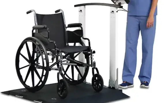
- The Summit SB-1150 bariatric wheelchair scale is a heavy-duty scale that offers exceptional performance in clinics and hospitals. Patients walk or can be wheeled onto the weighing platform to be
- weighed. The scale is a fully electronic, low profile floor scale that measures 36 in x 36 in (.91 m x .91 m) and has a capacity up to 1000 lb (500 kg). The SB-1150 uses four corner-mounted, alloy steel shear beam load cells with the cells recessed into the frame channels for protection.
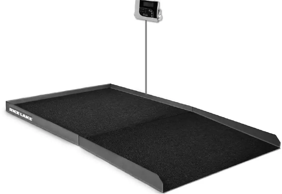
- The Summit SB-1150 comes with a large one inch LCD indicator display and 6 AA batteries for use when power is not available. There is an optional 120/220V AC adapter which can be purchased.
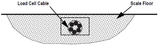
Load cell cables run through the main channels and are held down with replaceable cable ties near each corner to eliminate the possibility of cable damage. One threaded hole, located in the center of the deck, allows for placement of a removable eyebolt for lifting the scale from above with chains. The scale must always be lifted from above with chains through the eybolt to avoid the possibility of foot and load cell damage from forklift tines. Adjustable feet allow for leveling the scale in the event of minor floor irregularities.
FCC Compliance
United States
This equipment has been tested and found to comply with the limits for a Class A digital device, pursuant to Part 15 of the FCC Rules. These limits are designed to provide reasonable protection against harmful interference when the equipment is operated in a commercial environment. This equipment generates, uses, and can radiate radio frequency energy and, if not installed and used in accordance with the instruction manual, may cause harmful interference to radio communications. Operation of this equipment in a residential area is likely to cause harmful interference in which case the user will be required to correct the interference at his own expense.
Canada
This digital apparatus does not exceed the Class A limits for radio noise emissions from digital apparatus set out in the Radio Interference Regulations of the Canadian Department of Communications.
Safety
Safety Definitions:
- DANGER
Indicates an imminently hazardous situation that, if not avoided, will result in death or serious injury. Includes hazards that are exposed when guards are removed. - WARNING
Indicates a potentially hazardous situation that, if not avoided, could result in serious injury or death. Includes hazards that are exposed when guards are removed. - CAUTION
Indicates a potentially hazardous situation that, if not avoided, could result in minor or moderate injury. - IMPORTANT
Indicates information about procedures that, if not observed, could result in damage to equipment or corruption to and loss of data.
General Safety
Do not operate or work on this equipment unless this manual has been read and all instructions are understood. Failure to follow the instructions or heed the warnings could result in injury or death. Contact any Rice Lake Weighing Systems dealer for replacement manuals.
WARNING
Failure to heed could result in serious injury or death.
Ensure every individual who operates or works with this unit has read and understands all safety information.
- Do not transport the scale while someone is on the scale.
- Do not allow minors (children) or inexperienced persons to operate this scale.
- Do not use in the presence of flammable materials.
- Do not use this product if any of the components are loose or cracked.
- Do not use near water.
- Do not use the scale on slippery surfaces, such as a wet floor.
- Do not use this scale when a person’s body or feet are wet, such as after taking a bath.
- Do not place fingers into slots or possible pinch points.
- To avoid cross contamination, the scale should be cleaned regularly.
- Prior to cleaning, make sure the scale is disconnected from the power source.
- People with disabilities, or who are physically frail, should always be assisted by another person when using this scale.
IMPORTANT
- Do not drop the scale or subject it to violent shocks.
- Do not jump on the scale.
- For accurate weighing, the scale must be placed on a flat, stable surface.
- Operating at voltages and frequencies other than specified could damage the equipment.
- Avoid contact with excessive moisture.
- Do not make alterations or modifications to the scale.
- Rice Lake Weighing Systems offers optional AC adapters; utilizing an adapter not supplied by Rice Lake Weighing Systems voids all warranties and approvals.
- Weight exceeding the maximum capacity may damage the scale.
Installation
The following section provides installation instructions for the Summit SB-1150 wheelchair scale.
Scale
Standard installation of the scale consists of the following:
- Site preparation
- Unpacking the scale
- Assembly
- Electrical interface to the indicator
- Load cell connections
- Powering the scale
Site Preparation
Consider the following when choosing a site for the scale:
- Select a site where overweight loads can maneuver easily without crossing the platform
- Avoid areas where damage could occur from side impacts of wheels or forklift tines
- Avoid areas where falling objects could cause shock damage
- Avoid areas where water may damage a scale not meant for a washdown environment
- The scale must be level within 1/4 in of horizontal
- The interface cable between the scale and the indicator must be protected from crushing, cutting and moisture damage
IMPORTANT
- The scale must not be loaded beyond capacity, even momentarily.
- Choose a site where the floor is level to 1/4 in to avoid excessive shimming. The floor may require modification if unable to select an area up to this standard.
- If the chosen site has potential dangers to cable integrity, cable protection is required, such as running the cable in conduit.
Unpacking
Remove all packing material and inspect the contents for damage possibly caused during shipment. Contact Rice Lake Weighing Systems and the shipper immediately if there is damage to the scale. The shipping container should contain the scale, this manual, scale feet, the indicator, and a 10 foot length of load cell cable.
The Summit SB-1150 wheelchair scale has one threaded hole located in the center of the deck to allow for the installation of an eyebolt. An eyebolt hook and chains can be used to lift the scale. It is recommended to use a 1/2 in-20NF eyebolt for lifting the scale.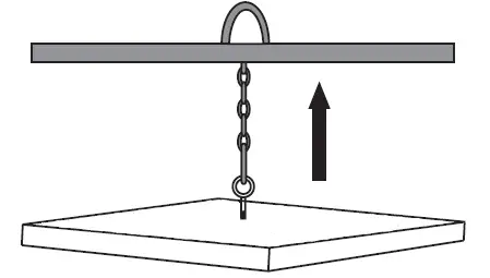
Assembly
The scale feet are shipped detached from the scale for load cell protection during shipment.
- Unpack all parts.
- Ensure each foot is screwed in until the foot touches either the load cell or the underside of the deck.
- Unscrew each foot three complete turns and level the scale so all of the feet are in contact with the floor.
- Place a spirit level on the scale deck.
- Adjust corners not contacting the floor by unscrewing the feet until the feet contact the floor surface.
- When all of the feet are contacting the floor, check the deck with the spirit level to ensure the scale is within 1/4 in of level.
Electrical Interface to the Indicator
Ten feet of 4-wire cable for connecting the scale to the weight indicator is supplied with each scale. The junction box is accessible through an access plate located on the side of the scale. Use the following steps to wire the junction box:
- Remove the two #10 x 3/8 in screws.
- Slide the junction box assembly out of the deck.
- Open and remove the top of junction box.
- Push the cable end into the junction box through a cord grip.
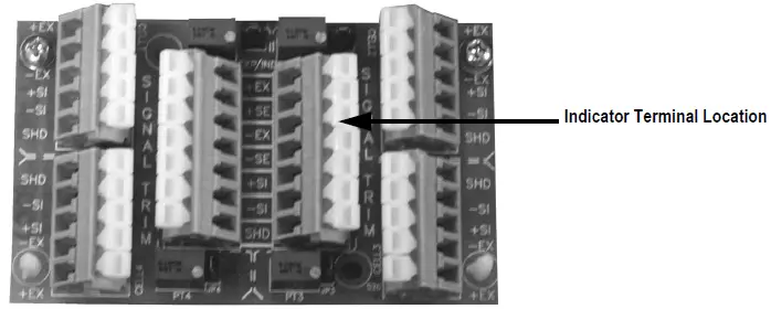
- Connect the wires to the indicator terminal

Cable Color Code
Junction Box
White
+EXCITATION Green -EXCITATION
Black
+SIGNAL Red -SIGNAL
Bare
Shield
- Pull out excess and tighten the cord grip to hold the cable snugly.
- The cable must be routed to the indicator in a manner that will protect the cable from damage. The method of cable protection in non-washdown applications
 . Leave a loose coil of excess cable under the scale to facilitate lifting of the scale for servicing and cleaning.
 - Complete the connections to the indicator once the cable is protected and in its final position.
- Ensure all strain relief fittings are tight.
- Trim corners if necessary.
- Replace the junction box cover and slide the junction box back into the scale deck.
- Replace the access plate and secure with the screw removed in Step 1 on page 4.
 . Leave a loose coil of excess cable under the scale to facilitate lifting of the scale for servicing and cleaning.
Insert Batteries
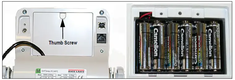
The six AA batteries supplied with the scale provide an average of 25 hours of continuous use. To install the batteries:
- Turn thumbscrew counterclockwise then remove battery cover.
- Insert batteries into the battery chamber as illustrated.

- Put the cover in place and turn the thumbscrew clockwise to secure.
Note
- Remove the batteries prior to storing if the product is not going to be used for an extended period of time.
- If the LO BAT indicator activates, for accurate weighing, replace the batteries or connect the scale to an AC power source as soon as possible.
Power Connection
An optional AC power adapter can be used when a power outlet is available.
IMPORTANT
Only use power adapters supplied by or purchased from Rice Lake Weighing Systems. The use of a power adapter not from Rice Lake Weighing Systems voids the warranty.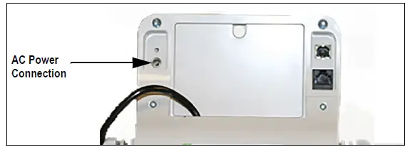 Note
Note
- The battery annunciator on the display turns off when using an AC power connection.
- The brightness of the backlight is reduced to 60% when using battery power.
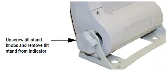
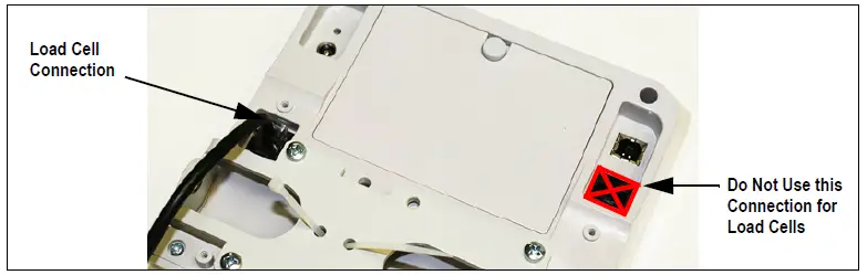
Load Cell Connections
The indicator and scale comes factory installed with a load cell cable connection. Follow the procedure below if the load cell cable needs to be replaced or reconnected to the indicator.
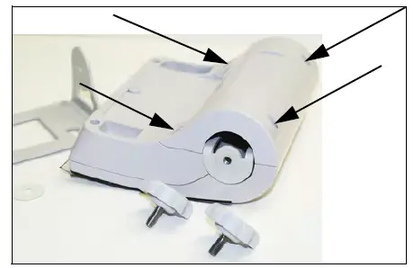
- Unscrew and remove the tilt stand bracket from the indicator to gain access to the load cell connection.

- Remove the four back retaining screws to remove the back cover to the indicato

- Plug the end of the load cell cable into the load cell connection. When it clicks the load cell cable is properly seated into the connection.

- Reinstall the back cover and attach to the tilt stand.
Operation
This section describes the front panel and includes procedures for operation of the scale.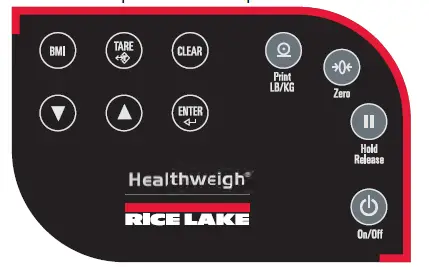
Key Descriptions
The display has 10 front panel keys. Key functions are described in the table below.
IMPORTANT
The front panel keys are very sensitive, so only a gentle press is required.
| Key | Name | Function |
| On/Off | On/Off | Powers the scale on or off |
| Print LB/KG | Print LB/KG | Sends data out from the RS-232 port; Allows to toggle between kilograms and pounds providing that it is enabled in Configuration mode; Cannot toggle while in the BMI mode |
| Zero | Zero | Only functions if the current weight is stable and less than 2% of the capacity of the scale. Anything over 2% requires a recalibration |
| Hold/ Release | Hold Release | Displays most current weight value on the display and holds that value when the patient is off the scale. A second press releases the weight value. Not active while in BMI mode |
| BMI | BMI | Pressing the BMI key enables access to the BMI (Body Mass Index) mode (defaults when scale is turned on). The patient is gets on the scale, weight stabilizes and press the BMI key. The display then asks for the patient height to calculate out the patient BMI. |
| TARE | TARE | Used to remove the weight initially of anything on the scale that shouldn’t be included in the total weight of the patient on the scale |
| CLEAR | CLEAR | When using the BMI function, the display looks for a height entry. Pressing Clear changes this entry back to 190.0 cm (default) or 5 ft, 7.5 in.Once BMI is displayed, pressing the Clear key exits BMI |
| ENTER | ENTER | Used to accept height in BMI mode; accepts the value of the parameter last entered and moves to the next stage Pressing and holding Enter during startup will display ID. This is the first setup on entering into configuration mode |
| Up | Up Arrows | Adjusts the value of the flashing digit/number Adjusts height input (0.5 in/0.5 cm) while in BMI mode |
| Down | Down Arrows | Adjusts the value of the flashing digit/number Adjusts height input (0.5 in/0.5 cm) while in BMI mode |
Weighing
Use the following steps to weigh
- Press
 to turn on the scale. 0.0 appears on the display along with the ZERO annunciator.
 - Place the patient on the scale. The patient’s weight is displayed, the LOCK annunciator is on and the indicator beeps to indicate the end of the weighing process.
- Press
 to change the display from lb to kg and vice-versa.
 - Press and hold until OFF displays to turn off the scale.
Hold/Release Function
Use the following steps to use the Hold/Release function.
- Press to turn on the scale. 0.0 prompts along with ZERO on the display.
- Press
 once the patient’s weight stabilizes. The patient’s weight and the HOLD and LOCK annunciators remain on the display when the patient is off the scale.
 - Press again to return the scale to zero.
Note
Pressing ![]() will not work while using Hold/Release function.
will not work while using Hold/Release function.
Pressing ![]() prior to the patient getting on the scale will also hold the weight display.
prior to the patient getting on the scale will also hold the weight display.
Preset Tare
Use the following steps for the Preset Tare function prior to patient weighing if additional items are being used by the patient.
- Press to turn on the 0.0 appears on the display along with the ZERO annunciator.
- Place additional item(s) on the
- Press
 until the display returns to 0 and NET annunciator appears on the display.
 - Remove additional item(s) from the The weight displays with a negative symbol to the left of it.
Not removing the additional item(s) prior to patient weighing will also work. - Position the patient and additional item(s) on the The display identifies the patient weight. The NET annunciator is still active. The weight of the additional item(s) remains stored in memory for the duration of this weigh in.
- To cancel the tare weight, remove patient from the scale and press until NET disappears from the display and the display turns back to 0 and GROSS appears.
 until the display returns to 0 and NET annunciator appears on the display.
Tare weight is also canceled when the scale is turned off.
Toggle Tare
Use the following steps to use the Toggle Tare function when the additional item to be weighed is known.
- Press when the scale is empty and 0 displays. The default values prompts while 0.0 is flashing on the display (default is programmed to be 33.0 lb/15.0 kg).
- Use
 and
and  to adjust the Press
 to start the tare function. The NET annunciator turns on instead of the GROSS annunciator.
 and
and  to adjust the Press
 to start the tare function. The NET annunciator turns on instead of the GROSS annunciator.
Using the Body Mass Index (BMI) Function
Use the following steps in determining the BMI.
LB Mode
- Ensure that the scale is at
- Place the patient on the scale to obtain a The LOCK annunciator appears on the display.
- Press
 . The BMI and FT/IN annunciators appear on the display and a default height value of 5 feet – 5 inch (5 – 07.5) is flashing.
 - Use and to adjust the height
- Press
- The BMI value and BMI annunciator are shown on the Press
 to return to the Weighing mode and the BMI function will be turned off.
 . The BMI and FT/IN annunciators appear on the display and a default height value of 5 feet – 5 inch (5 – 07.5) is flashing.
KG Mode
- Ensure that the scale is at
- Place the patient on the scale to obtain a The LOCK annunciator appears on the display.
- Press The BMI and CM annunciators appear on the display and a default height value of 0 cm (170.0) is flashing.
- Use and to adjust the height
- Press
- The BMI value and BMI annunciator are shown on the Press to return to the Weighing mode and the BMI function will be turned off.
 to return to the Weighing mode and the BMI function will be turned off.
Troubleshooting
Refer to the following table to check and correct any failure before contacting service personnel.
Symptom | Possible Cause | Corrective Action |
| Scale does not turn on | Dead batteries | Replace batteries or connect to AC power |
| Faulty electrical outlet | Use a different electrical outlet | |
| Bad power supply | Replace adapter | |
| Questionable weight or the scale does not zero | External object is interfering with the scale | Remove the interfering object from the scale |
| Display did not show 0.0 before weighing | Help the patient off the scale, zero the scale and begin the weighing process again | |
| Scale is not placed on a level floor | Ensure scale is level and begin the weighing process again | |
| Scale is out of calibration | Check the weight with a certified calibration weight | |
| Scale base is touching floor during a weighment | Adjust height of feet so fingers can slide between the base of scale and the floor all the way around the platform | |
| The display shows a STOP message | The load on the scale exceeds the capacity of the scale | Remove the excess weight and use the scale according to manufacture specifications |
| The display shows LO Bat message | The battery is low | Replace batteries |
The display shows E and Err messages as detailed below | ||
| E06 | Identifier – ADC | AD too high |
| E07 | AD too low | |
| E10 | Overload | Scale has been overloaded. Remove load from scale |
| E4L | BAT | Battery low, but still usable- one bar left on indicator display |
| E4U | Battery low and unstable – no bars left on indicator display | |
| E11 | CAL | Calibration Error – recalibrate scale |
| Err 1 | Load cell cable may be plugged into wrong connection port | Ensure cable is connected to the load cell connection port. Note: Load cell connection point is located underneath the curved plastic cover of the indicator. Remove four back retaining screws, remove curved back cover to access load cell connection point. |
| Err 2 | Low saturation state (low A/D) | The load cell is not connected properly; Check the cables and mechanical connections; if the problem persists, replace the set of load cells |
| Err 3 | High saturation state (high A/D) | See Err 2 |
| Err 6 | Unstable weight; Cannot calibrate | Check the load cell mechanical surroundings and ensure nothing is contacting the load cell and that the cables are properly welded |
| Err 7 | Scale isn’t moving | Make sure feet are installed on the scale. Turn the feet all the way in and then back them out three full turns, then level the scale |
| SAT | Damaged load cell cable | Replace load cell cable |
| Load cell cable may be plugged into wrong connection port | Ensure cable is connected to the load cell connection port. Note: Load cell connection point is located underneath the curved plastic cover of the indicator. Remove four back retaining screws, remove curved back cover to access load cell connection point. | |
Communications
The unit comes with an RS-232 port that enables weight data to be transmitted to other equipment, such as a computer or printer. The RS-232 cable with DB-9 connector (PN 100719) is available from Rice Lake Weighing Systems. That connection is shown in USB Connection section on the next page.
The RS-232 parameters are:
- 9600 baud (selectable in the programming mode)
- 8 data bits
- 1 stop bit
- no parity
- no handshaking
There are three methods of communication:
- Push-button keypad print
- Standard remote protocol
- Escape protocol
With a stable, in-range weight, press and hold for at least three seconds, or until the scale emits two quick beeps.
Note
If the scale does not beep after five seconds, release![]() as the weight was either in motion or out of range.
as the weight was either in motion or out of range.
If displaying weight and not BMI, the scale will send out the following 21 character string:
xxxxxxxxx<SP>uu<SP>mmmmm<SP><CR><LF>
Token | Description |
| xxxxxxxxx | Weight with decimal point and “-” sign |
| <SP> | Space |
| uu | Unit – lb or kg |
| mmmmm | Mode – gross or net |
| <CR> | Carriage return |
| <LF> | Line feed (moves cursor down to the next line) |
Example:
– 10 Lb net = <SP><SP><SP><SP>-10.0<SP>lb<SP><SP>Net<SP><SP><SP><CR><LF>
10 Lb gross = <SP><SP><SP><SP><SP>10.0<SP>lb<SP>Gross<SP><CR><LF>
The scale will send out the following data while in BMI mode (displaying the BMI value):
Setting | Value |
| Gross Weight | 215 Lb |
Tare Weight | 0.0 Lb |
| Net Weight | 215 Lb |
Patient Height | 6-01.0 ft |
| Patient BMI | 28.4 |
USB Connection
The scale has the capability of connecting to a Windows® computer (PC) using a USB cable (not included) and a terminal emulation program. A terminal emulation program allows the transfer of data between the scale and PC using a serial port.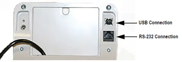 Note
Note
Apple® and Macintosh® computers are unable to transfer the necessary data to the scale. Only use a PC for data transfer
Connecting software and downloads should always be addressed by the IT department for safety reasons and can vary depending on what type of computer platform is being used.
Note
Consult the IT department if driver protections are preventing the use of the USB driver. Driver protections may need to be temporarily disabled on Windows 10 or later computers to allow for the installation of the USB driver.
- Connect the scale’s indicator to a PC using a USB-Type B to USB-Type A cable (not included).
- Turn the indicator on.
Note
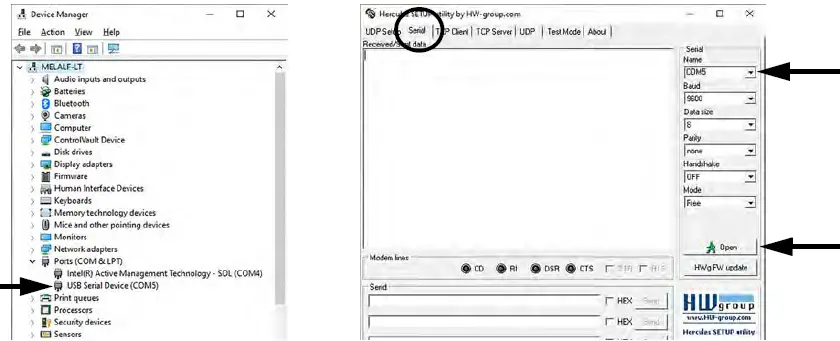
In most cases, the PC should find the driver and automatically configure the driver when the scale is plugged into a USB port. - Open a terminal emulation program, such as Advanced Serial Port Terminal, pUtty or Hercules (used in this example).
- Connect to the serial port assigned by the PC (COM5 in example). This can be found in Device Manager. Once selected, press Open.

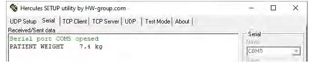
- With weight on the scale, press and hold the Print button on the indicator for three seconds. The patient’s weight is sent to the PC.

Maintenance
The following section provides instructions for maintaining and cleaning the unit.
IMPORTANT
- Do not immerse the scale in cleaning or other liquid solutions.
- Do not use Isopropyl alcohol or other solutions to clean the indicator display surface.
Basic Maintenance
Before the first use of the scale and after periods of non-use, check the scale for proper operation and function. If the scale does not operate correctly, contact a qualified service personnel.
Go through the following steps for basic maintenance.
- Check the overall appearance of the entire scale for any obvious signs of damage
- Inspect the condition of the AC power adapter cord for cracking, fraying or for broken or bent prongs
Cleaning
Proper care and cleaning is essential to ensure a long life of accurate and effective operation. Before beginning the cleaning process, disconnect the scale from the AC power source.
- Clean all external surfaces with a clean, damp cloth or tissue. Mild soap and water solution may be used. Dry with a clean soft cloth
- Do not immerse the scale into cleaning or other liquid solutions
- Do not use Isopropyl alcohol or other solutions to clean the display surface
Specifications
- Power
120 VAC-9VDC-60Hz / 230 VAC-9VDC-50Hz - Battery Type
AA Alkaline – 25 hours of continuous use - Battery Use
25 hours continuous use
Automatic power-off can be configured - Electrical Grounding
For systems where the scale is connected to a 115 VAC circuit, the indicator must be directly connected to an earth ground with a ground interface cable of no more than 3W resistance throughout its length. - Load Cell Excitation
Rated excitation 10 VDC
Maximum excitation 15 VDC - Environmental
Operating Temperature 50°F to 104°F (14°C to 40°C)
Storage Temperature 32°F to 158°F (0°C to 70°C)
Humidity 85% relative humidity - Safe Static Overloading Capacity
Maximum: 150% of scale capacity - Grade Level Requirements
The supporting surface for the four feet of the scale must be level within 1/4 inch of horizontal - Dimensions
Scale (W x L x H) 36 in x 36 in x 3.0 in (915 mm x 915 mm x 76 mm)
Ramp (W x L) 36 in x 28.5 in (915 mm x 724 mm)
Certifications and Approvals


