HAMMER-IMS Rio Module Is The Mm-Wave Basis-Weight Measurement Device
Overview
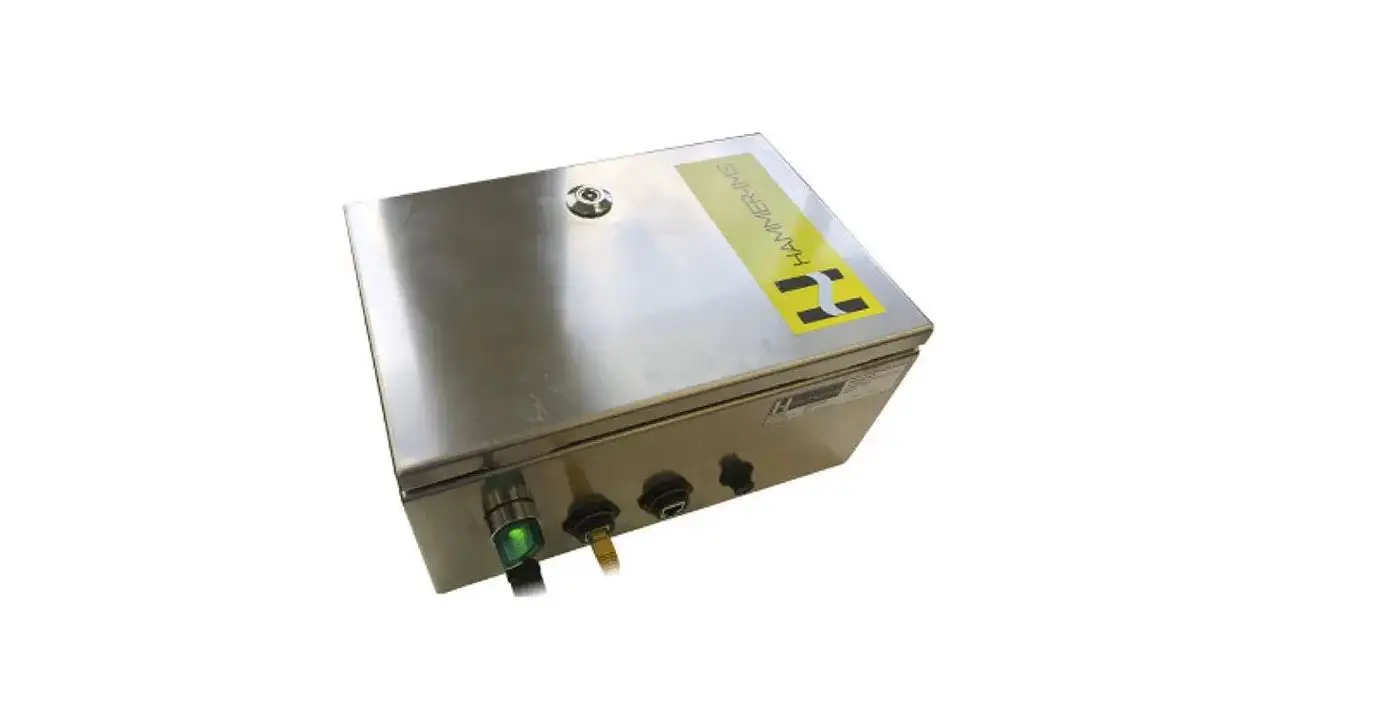
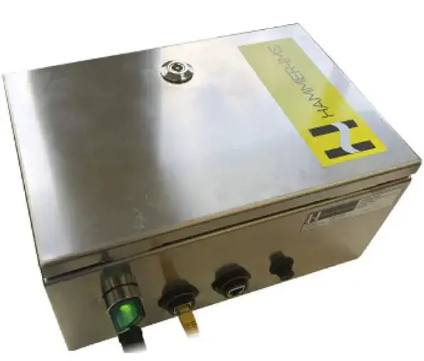
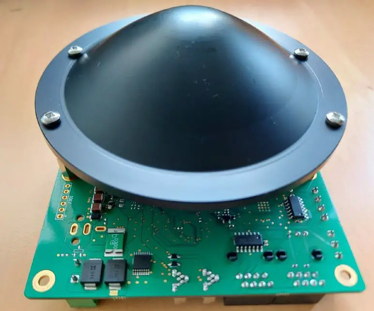
The Rio module is the mm-wave basis-weight measurement device developed by Hammer-IMS. The board is equipped with a 60 GHz measurement transceiver. The measurement data is available on a proprietary RS485 interface.
Caution: Electrostatic sensitive device: Observe precaution when handling!
Installation should only be performed by Hammer-IMS personnel. The module is not intended for resale.
A minimum distance of at least 20cm between the device and any person should be kept at all time.
- This limited module is only valid to be installed in the host as described in the supplied manual, any additional host(s) would require subsequent permissive change to perform the assessment of radiated emission.
- Any installation to the host requires part 15B as per host dependent.
- The module is only valid with the equipped antenna, any change of the type, and gain would require to be re-evaluated as per FCC permissive change policy.
- This module is only valid with 20cm safety distance installation. The change of the host to fixed, and portable platform would require to perform re-assessment on RF exposure as per permissive change policy.
- host vendor shall be given the related compliance text, such as part 15.21, 15.19, 15.105, and RF exposure on the instruction manual given to the end user.
FCC Compliance statement
USA
This device complies with Part 15 of the FCC Rules. Operation is subject to the following two conditions:
- This device may not cause harmful interference, and
- this device must accept any interference received, including interference that may cause undesired operation.
Any changes or modifications not expressly approved by the party responsible for compliance could void the user’s authority to operate this equipment.
Kanada
“Operation is subject to the following two conditions: (1) this device may not cause interference, and (2) this device must accept any interference, including interference that may cause undesired operation of the device.”
Any changes or modifications not expressly approved by the party responsible for compliance could void the user’s authority to operate this equipment.
FCC/IC Requirements
This device complies with Industry Canada licence-exempt RSS standard(s) and part 15 of the FCC Rules.
Operation is subject to the following two conditions:
- this device may not cause interference, and
- this device must accept any interference, including interference that may cause undesired operation of the device.
This equipment complies with FCC RF radiation exposure and IC RSS-102 radiation exposure limits set forth for an uncontrolled environment. This equipment should be installed and operated with the minimum distance 20cm between the radiator & your body.
Changes or modifications not expressly approved by the party responsible for compliance could void the user`s authority to operate the equipment.
Mechanical Installation
The Rio module should never be used without proper reflector plate.
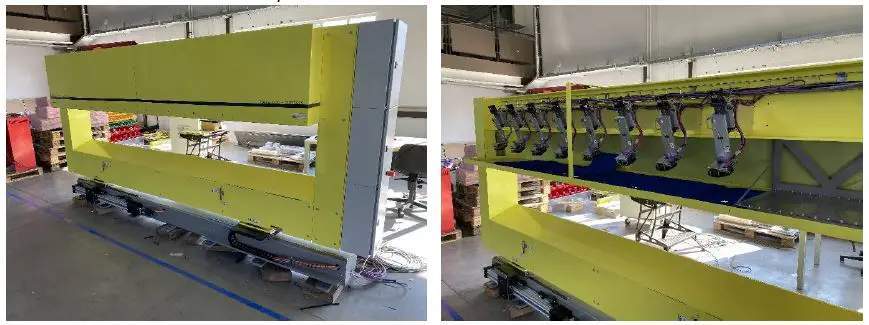
Modification or replacement of the lens antenna is never allowed. Proper operation or safety is not guaranteed if the lens is changed. 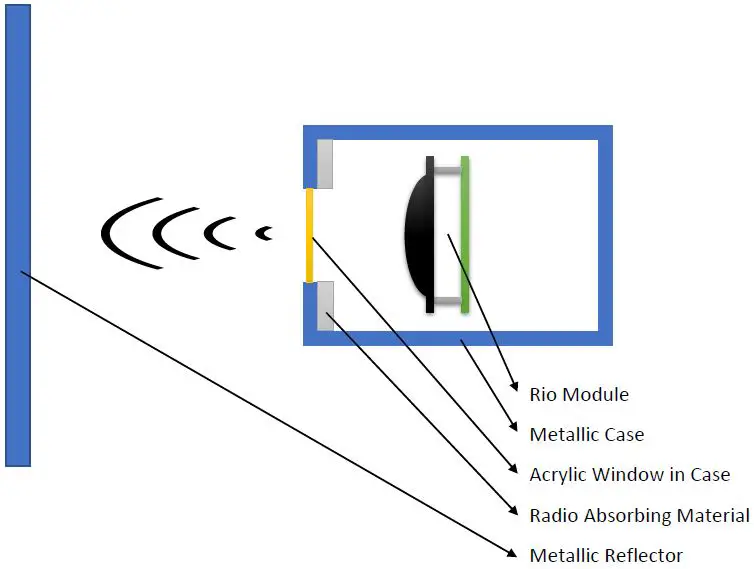 Mount the Rio module inside a closed metallic case. This can either be a cabinet like the OEM module or a closed tube as used in many 0-frame or C-frame machines.
An opening should be made in front of the Rio lens to allow the measurement waves to leave and re-enter the cabinet. An acrylic sheet can be used to cover the window in order to make the machine less prone to dust.
Parallel to the Rio module, a metallic reflector needs to be placed the reflect the radiated electromagnetic waves back into the module. Recommended size is 250mm x 250mm minimum and it can be placed at a distance between 100mm and 1000mm.
To optimize performance and measurement spot, radio absorbing material can be placed at the inside of the case reducing the window size. This eliminates unwanted reflections of the waves inside the case.
Label
A label must be attached to the outside of the case indicating the machine contains one or more Rio modules:
Switches and Jumpers 
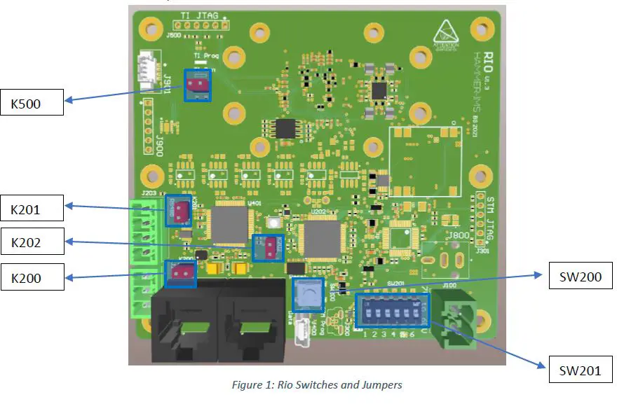
DIP switch SW201
The 6-switch dip-switch can be used to control some of the software settings of the Tokyo board.
Switches 1 to 4:
Control the head address of the board. When a system using multiple heads is built, it is important to have a different identification address for all heads.
The address is calculated in the following way:
Address = 0xFF – SW
where SW is the four bit representation of switches 1 to 4 of SW201.
| Address | Switch 4 | Switch 3 | Switch 2 | Switch 1 |
| 0xFF | OFF | OFF | OFF | OFF |
| 0xFE | OFF | OFF | OFF | ON |
| 0xFD | OFF | OFF | ON | OFF |
| 0xFC | OFF | OFF | ON | ON |
| 0xFB | OFF | ON | OFF | OFF |
| 0xFA | OFF | ON | OFF | ON |
| 0xF9 | OFF | ON | ON | OFF |
| 0xF8 | OFF | ON | ON | ON |
| 0xF7 | ON | OFF | OFF | OFF |
| 0xF6 | ON | OFF | OFF | ON |
| 0xF5 | ON | OFF | ON | OFF |
| 0xF4 | ON | OFF | ON | ON |
| 0xF3 | ON | ON | OFF | OFF |
| 0xF2 | ON | ON | OFF | ON |
| 0xF1 | ON | ON | ON | OFF |
| 0xF0 | ON | ON | ON | ON |
Switch 5:
Future use. The function of this switch is currently undefined and should be kept to the OFF position.
Switch 6:
Selection of the frequency tap on which the measurement is performed.
| Tap | Switch 6 |
| 15 | OFF |
| 16 | ON |
Reset switch SW200
The reset pushbutton SW200 when pushed will reset the STM32 processor U202 and IWR6843AOP transceiver U500.
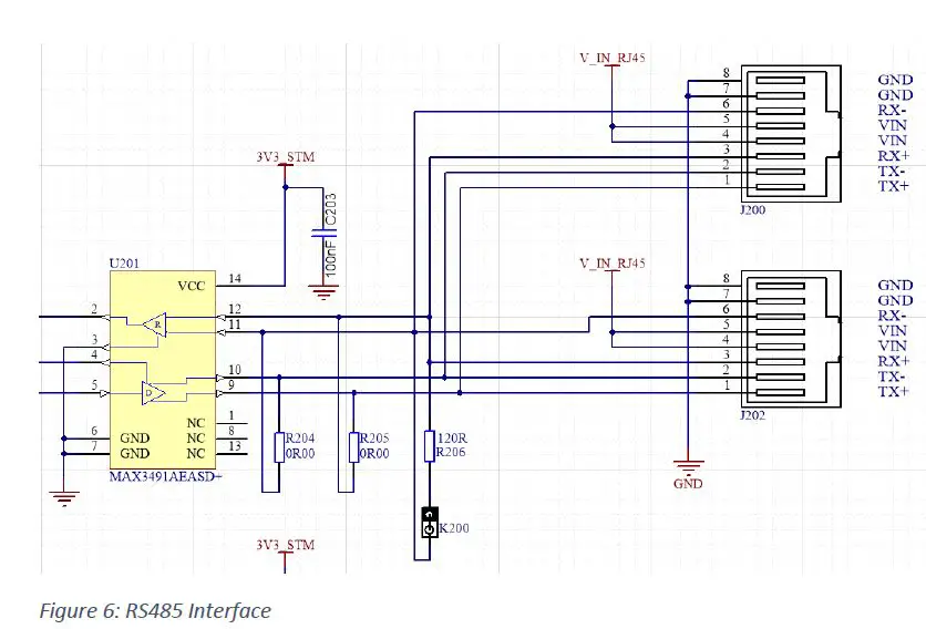
Jumper K200: main RS485 Termination
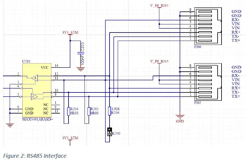
Figure 2: RS485 Interface
When jumper K200 is equipped, a 120 Ohm termination resistor is enabled between the RX- and RX+ terminals of the main RS485 bus. This jumper should be equipped when the Rio bord is connected to the RS485 bus using long wires and this particular board is the physically last one connected to the daisy chain bus.
Jumper K201: aux RS485 Termination
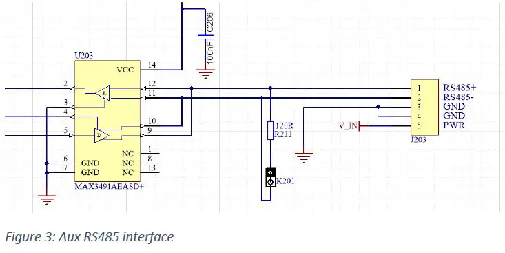 When jumper K201 is equipped, a 120 Ohm termination resistor is enabled between the RX- and RX+ terminals of the main RS485 bus. This jumper should be equipped when using long cables to connect a device to the aux RS485 bus.
Jumper K500: IWR6843AOP programming mode
When a jumper is present on K500, the IWR6843AOP will boot in programming mode. In this mode, new firmware can be uploaded to the IWR6843AOP processor using the Uniflash tool. Programming needs to be performed using the USB bus.
Jumper K202: STM32F303RE programming mode
Jumper K202 selects the boot mode of the STM32F303RE. Without jumper, the processor will be in normal RUN mode. When a jumper is present, the STM32F303RE will boot in programming mode. Programming can then be done using the RS485 bus with the STM32CubeProgrammer tool.
Connectors 
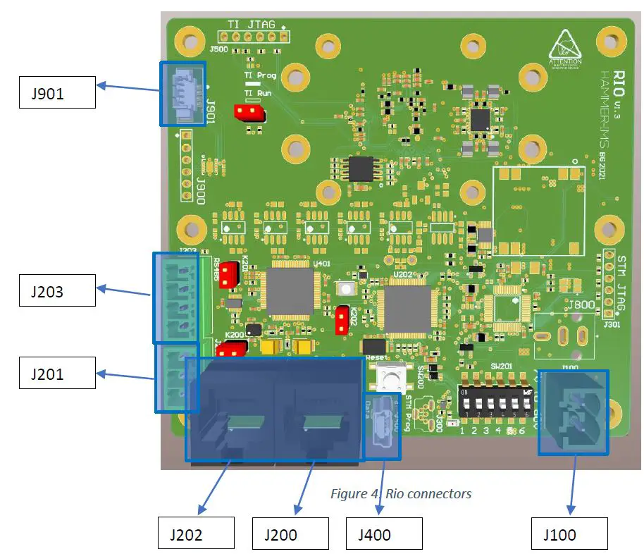
J100: Power supply
The Rio board must be powered by an external DC power supply. The voltage of this supply should be between 7V and 60V while the board consumes approx. 4W.
J400: Maintenance USB port
The USB port is used for diagnostics and reprogramming purposes. The port should be left unconnected in normal use.
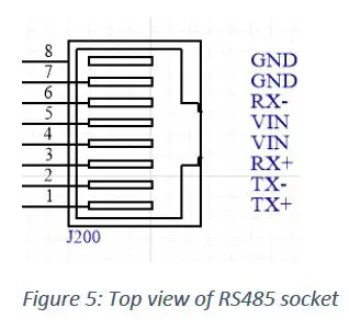
J200/J202: RS485 port
These RJ45 connectors are used for the data connection of the Rio module. Please check the user’s manual for detailed information on the data protocol.
J200 and J202 are internally connected to each other to make daisy chaining the data connection of the Rio boards. Pinning of both connectors are identical so they are exchangeable.
 J201: Analog Input
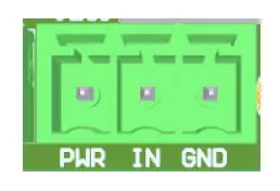
The Rio board has an analog 0-10V input. The three pole connector also carries a power output (connected to power input) to power an external analog sensor.
J203: Aux RS485
The auxiliary RS485 port is currently unsupported and should be left unconnected.
J901: Capacitive Measurement Interface
This connector is used to connect the optional Hammer-IMS capacitive measurement module. If the module is not installed, please leave this connector unconnected.
Lens Antenna 
The Rio module comes equipped with a lens antenna. The user should never remove this antenna from the board. Operation and safety is not guaranteed when the antenna is not present.


 Weigh Scale Ship Series Digital Operational Manual")


