ZENMUSE L1
User Manual v1.0
2021.05
![]()
 Searching for Keywords
 Searching for Keywords
Search for keywords such as “battery” and “install” to find a topic. If you are using Adobe Acrobat Reader to read this document, press Ctrl+F on Windows or Command+F on Mac to begin a search.
 Navigating to a Topic
 Navigating to a Topic
View a complete list of topics in the table of contents. Click on a topic to navigate to that section.
 Printing this Document
 Printing this Document
This document supports high resolution printing.
Using This Manual
Legends
![]() Important
Important ![]() Hints and Tips
Hints and Tips ![]() Reference
Reference
Caution
- The L1 is a precision instrument. DO NOT drop the L1 and handle with care.
- If highly accurate point cloud data is required, it is not recommended to use the L1 in low visibility conditions such as foggy or rainy weather. Otherwise, the detection range may be reduced resulting in point cloud noise being produced.
- DO NOT touch the optical window of the L1. Dust and stains on the optical window can negatively affect the performance. Use compressed air or a wet lens cloth to clean the optical window correctly. Refer to the Storage, Transportation, and Maintenance section for more information on how to clean optical windows.
- DO NOT touch the surface of the lens with your hand. Be careful to avoid scratching the surface of the lens with sharp objects. Otherwise, the quality of images may be affected. Clean the surface of the camera lens with a soft, dry, clean cloth. DO NOT use substances containing alcohol, benzene, thinners, other flammable substances, or alkaline detergents to clean or maintain the RGB Mapping Camera or Auxiliary Positioning Vision Sensor.
- When not in use, store the L1 in the storage case and replace the desiccant packet as necessary to prevent fogging the lenses due to excessive ambient humidity. If the lenses fog up, the water vapor will usually dissipate after powering on the device for a while. It is recommended to store the L1 in an environment with a relative humidity of less than 40% and temperature of 20±5° C.
- DO NOT place the product under direct sunlight, in areas with poor ventilation, or near a heat source such as a heater.
- DO NOT repeatedly power the product on or off. After powering off, wait at least 30 seconds before powering back on. Otherwise, the product life will be affected.
- Under stable laboratory conditions, the L1 achieves an IP54 protection rating by IEC 60529 standards. The protection rating is not permanent, however, and may reduce over an extended period.
- Make sure there is no liquid on the surface or in the port of the gimbal.
- Make sure the gimbal is securely installed on the aircraft and the microSD card slot cover is closed properly.
- Make sure the surface of the gimbal is dry before opening the microSD card slot cover.
- DO NOT remove or insert the microSD card when taking a photo or recording a video.
Product Profile
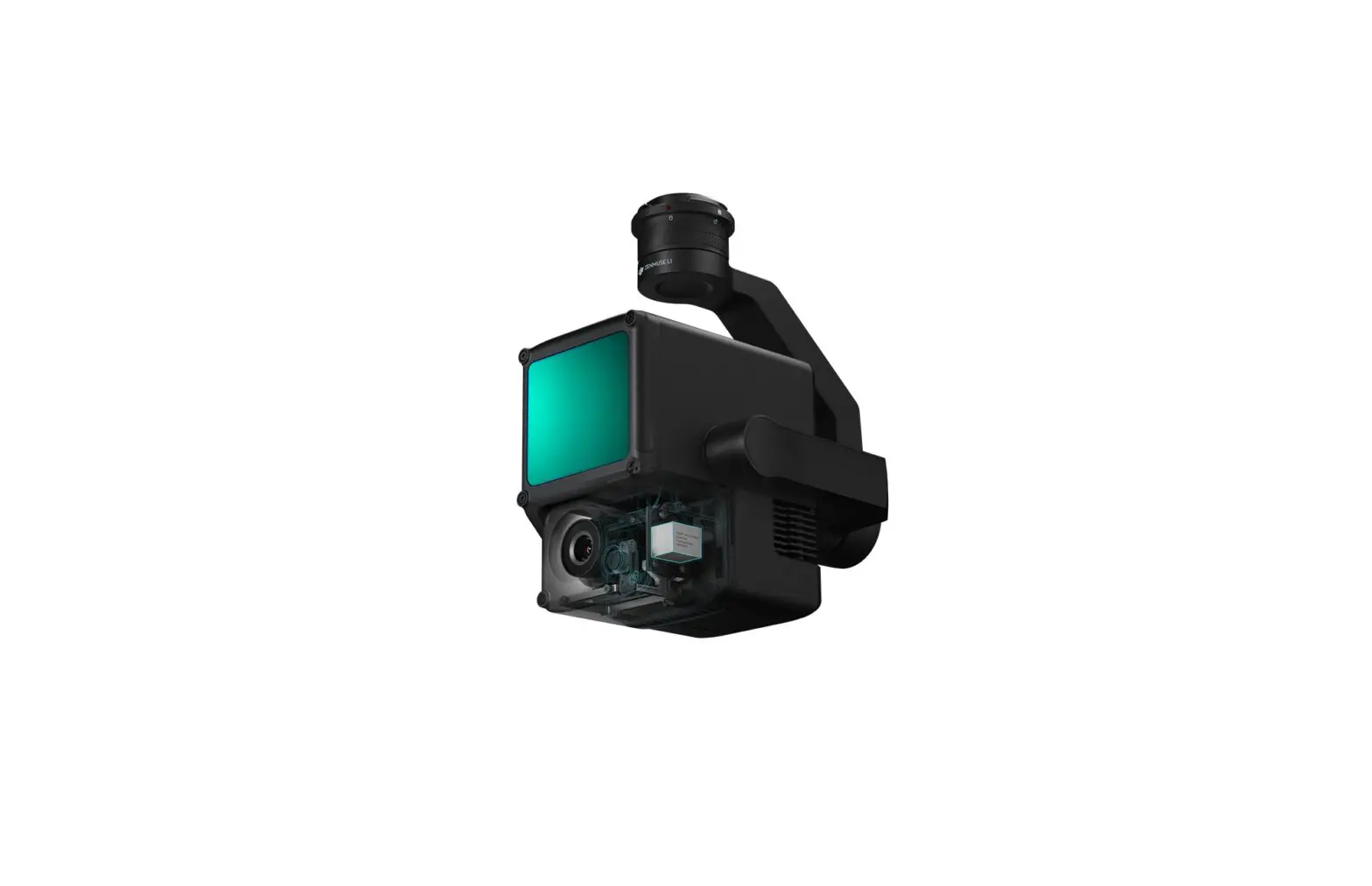
Introduction
The ZENMUSE™ L1 integrates a LIVOX™ LiDAR module, a high-accuracy IMU, and an RGB mapping camera on a 3-axis stabilized gimbal. When used with compatible DJI aircraft and DJI TERRA™, the L1 offers a complete solution that gives real-time 3D data throughout the day, which effectively captures the details of complex structures and delivers highly accurate reconstructed models.
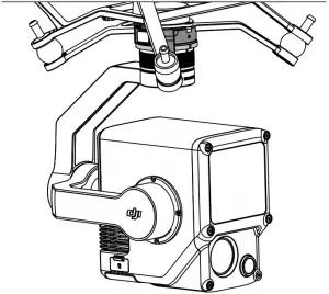
Overview
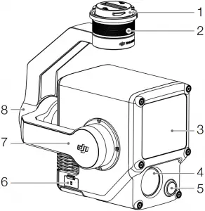
- Gimbal Connector
- Pan Motor
- LiDAR Sensor
- RGB Mapping Camera
- Auxiliary Positioning Vision Sensor
- microSD Card Slot
- Tilt Motor
- Roll Motor
Installation
Supported Aircraft
MATRICE™ 300 RTK
Installing on Aircraft
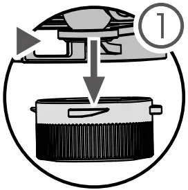
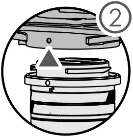
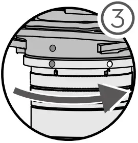
1. Remove the gimbal cap and lens protector.
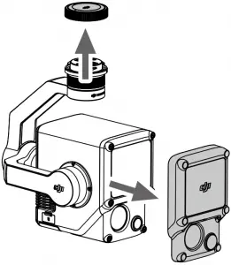
2. Press the button on the aircraft used for detaching the gimbal and camera. Rotate the gimbal cap on the aircraft to remove.
3. Align the white dot on the gimbal with the red dot on the aircraft and insert the gimbal.
4. Rotate the gimbal lock to the locked position by aligning the red dots.
 >
>  >
>  >
>

• Make sure the gimbal connector on the aircraft is positioned correctly when mounting. Otherwise, the L1 cannot be mounted.
• Only remove the L1 after powering off the aircraft.
• Remove the L1 by pressing the button on the aircraft to detach the gimbal and camera.
• Make sure the microSD card slot cover is firmly in place to prevent dust or moisture entering while using or during transportation. Failure to close the microSD card slot cover may cause the gimbal motor to overload during usage.
• To avoid burns, DO NOT directly touch the camera case when powering on.
• Detach the gimbal from the aircraft during transportation or storage. Otherwise, the service life of the gimbal dampers may be shortened or they may even be damaged.
Remote Controller Controls
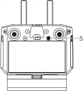
The Matrice 300 RTK remote controller is used as an example below. Adjust the tilt of the gimbal using the left dial and adjust the pan using the right dial. Press the shutter button or record button to take photos or record video. Toggle the 5D button to adjust the EV value. The customizable C1 button can be used to recenter the gimbal and the customizable C2 button can be used to switch between the main and auxiliary screen.
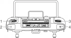
1. Left Dial
Turn to adjust the tilt of the gimbal.
2. Record Button
Press to start or stop recording video.
3. Shutter Button
Press to take a photo. The photo mode can be set to single or interval in DJI Pilot. Single photos can also be taken during video recording.
4. Right Dial
Turn to adjust the pan of the gimbal.
5. 5D Button
The default configuration is listed below. The configuration can be adjusted in DJI Pilot.
Left: Decrease EV value
Right: Increase EV value
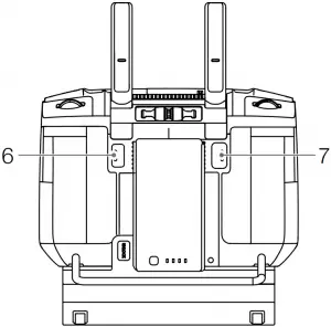
6. Customizable C2 Button
The default function is to switch between the main and auxiliary screen. The function for this button can be customized in DJI Pilot.
7. Customizable C1 Button
The default function is to recenter the gimbal. The function for this button can be customized in DJI Pilot.
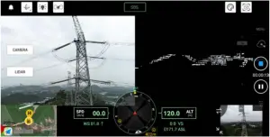
DJI Pilot App Controls
The touch interface can be used for capturing photos, recording videos, and viewing playback. Users can create a flight mission to record point cloud data in DJI Pilot.
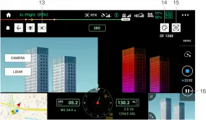
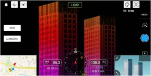
Basic Features
The touch interface can display a HD live view and offers professional photography configurations.
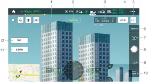
The interface may need to be updated. Make sure to update to the latest firmware.
1. Live HD Video
Displays the current camera view.
2. Camera Type
Displays the current camera type including camera view, point cloud view, and side-by-side view.
3. Camera Parameters
Displays the current camera parameters.
4. Focus Mode
Tap to switch between MF, AF-C, and AF-S focus mode.
5. Auto Exposure Lock
Tap to lock the exposure value.
6. Camera Settings
Tap to enter the photo and video settings. Tap ![]() to configure photo settings such as photo mode and image format. Tap
to configure photo settings such as photo mode and image format. Tap ![]() to configure video settings such as video size and format. Tap
to configure video settings such as video size and format. Tap ![]() to configure point cloud settings. Tap
to configure point cloud settings. Tap ![]() to configure video subtitles, grid, and smart LED settings. The settings may vary according to different camera models.
to configure video subtitles, grid, and smart LED settings. The settings may vary according to different camera models.
7. Recording Mode (Shutter/Video Record/Point Cloud Record)
Tap to switch between photo, video, and point cloud recording modes.
8. Shooting Button (Shutter/Video Record/Point Cloud Record)
Tap to take photos or start or stop recording video or point cloud data. The shutter and record buttons can also be used to take a photo and record video.
9. Playback
Tap to enter and preview photos and videos as soon as they are captured.
10. Parameter Settings
Tap to set ISO, shutter, exposure values, and other parameters.
11. Camera/Point Cloud Toggle
Tap to switch the main screen to the camera view or point cloud view.
12. Single/Dual View Toggle
Tap to switch the main screen to single or dual view.
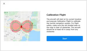
Point Cloud Recording View
13. Calibration Flight Button
Tap to perform a calibration flight to calibrate the LiDAR’s inertial navigation system and increase accuracy of reconstruction. Tap STOP to stop a calibration flight. Calibration flight should be performed at both the start and end of a flight. Make sure there are no obstacles within a 30m radius of the start and end points.
14. Color Palette
Tap to select a rendering mode including reflectivity, height, distance, and RGB.
15. Model Preview Button
Refer to the Point Cloud Model Preview section for more information.
16. Pause Button
Tap to pause point cloud recording and tap again to resume.
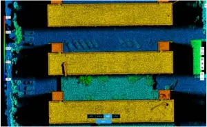
Point Cloud Model Preview
Tap to view the current point cloud model from different perspectives.
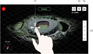
17. Use one finger to drag the point cloud model and use two fingers to rotate or zoom in or out on the point cloud model.
18. Tap ![]() to view the point cloud model beneath the aircraft.
to view the point cloud model beneath the aircraft.
19. Tap ![]() and the point cloud model will recenter and zoom in or out to display the whole model.
and the point cloud model will recenter and zoom in or out to display the whole model.
20. Tap to view the point cloud model from the top, north, east, south, or west.
Field Data Collection
Users can create a flight mission to record point cloud data in DJI Pilot and import the recorded data into DJI Terra for high-precision model reconstruction.
Preparation
- Make sure the L1 is installed correctly on the aircraft and that the aircraft and remote controller are linked after powering on.
- Go to camera view in DJI Pilot, select
 , then RTK, choose the RTK service type, and make sure that the status of RTK positioning and heading both display FIX. Refer to the Base Station Satellite Data Acquisition section for more information on data processing if the network or remote controller video transmission signal is poor.
 - Before recording data, it is recommended to warm up the L1 for 3 to 5 minutes after powering on. Wait until a prompt appears in the app stating that the payload INS IMU is warmed up.
Setting Camera Parameters
1. Go to the camera view in DJI Pilot and select ![]() .
.
2. Select ![]() to adjust the camera parameters according to the surroundings. Make sure the photo will be well exposed.
to adjust the camera parameters according to the surroundings. Make sure the photo will be well exposed.
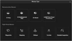
Mapping Mission
Enter the mission flight screen in DJI Pilot, select Create a Route, and then ![]() to choose a Mapping mission.
to choose a Mapping mission.
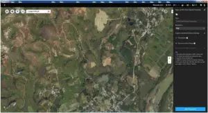
1. Tap and drag on the map to adjust the area that will be scanned.
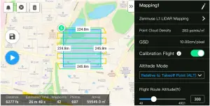
2. Edit the parameters for a LiDAR Mapping mission or Photogrammetry mission.
A. LiDAR Mapping mission:
a. Select Zenmuse L1 and then LiDAR Mapping.
b. Set the advanced settings, payload settings, and other parameters. It is recommended to set the Side Overlap (LiDAR) to 50% or above, the Scanning Mode to Repetitive, the altitude to 50-100 m, the flight speed to 5-10 m/s, and enable Calibration Flight.
B. Photogrammetry mission:
a. Select Zenmuse L1 and then Photogrammetry.
b. Set the advanced settings, payload settings, and other parameters. It is recommended to disable Dewarping and set Forward Overlap (Visible) and Side Overlap (Visible) to default parameters.
3. Select ![]() to save the flight mission and select
to save the flight mission and select ![]() to upload and execute the flight mission.
to upload and execute the flight mission.
4. Power off the aircraft after the mission is completed and remove the microSD card from the L1.
Connect it to a computer and check the point cloud data, photos, and other files in the DCIM folder.
Linear Flight Mission
1. Enter the mission flight screen in DJI Pilot, select Create a Route, and then ![]() to choose a Linear Flight mission.
to choose a Linear Flight mission.
2. Tap and drag on the map to adjust the area that will be scanned.
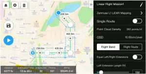
3. Edit the parameters for a LiDAR Mapping mission or Photogrammetry mission.
A. LiDAR Mapping mission:
a. Select Zenmuse L1 and then LiDAR Mapping.
b. Set the advanced settings, payload, flight band, flight route, and other parameters. It is recommended to enable Single Route. Set the altitude to 50-100 m, the flight speed to 5-10 m/s, and adjust the extension length to cover the area to be scanned.
B. Photogrammetry mission:
a. Select Zenmuse L1 and then Photogrammetry.
b. Set the advanced settings, payload settings, and other parameters. It is recommended to disable Dewarping and set Forward Overlap (Visible) and Side Overlap (Visible) to default parameters.
4. Select ![]() to save the flight mission and select
to save the flight mission and select ![]() to upload and execute the flight mission.
to upload and execute the flight mission.
5. Power off the aircraft after the mission is completed and remove the microSD card from the L1. Connect it to a computer and check the point cloud data, photos, and other files in the DCIM folder.
Manual Flight
1. Fly the aircraft to an appropriate height. It is recommended that the target be 5 to 100 meters away from the L1 and to perform a calibration flight. Tap ![]() , and
, and ![]() , and follow the prompts to finish the calibration. Make sure there are no obstacles within a 30m radius during calibration flight.
, and follow the prompts to finish the calibration. Make sure there are no obstacles within a 30m radius during calibration flight.
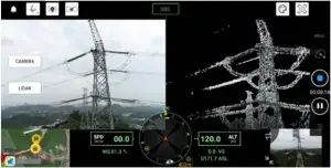
2. Fly the aircraft to the target you wish to record and use the camera view to adjust the gimbal to a suitable angle for recording point cloud data. Tap ![]() to enter point cloud view. Tap
to enter point cloud view. Tap ![]() to start point cloud recording.
to start point cloud recording.
3. Perform the flight mission to record point cloud data. Tap ![]() to view the point cloud model recorded in real time during flight.
to view the point cloud model recorded in real time during flight.
4. Return to the point cloud view and tap ![]() to finish recording.
to finish recording.
5. It is recommended to perform another calibration flight after recording the point cloud data.
6. Power off the aircraft after the mission is completed and remove the microSD card from the L1. Connect it to a computer and check the point cloud data, photos, and other files in the DCIM folder.
Point Cloud Data File Description
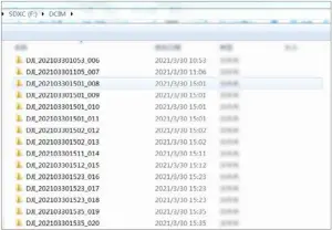
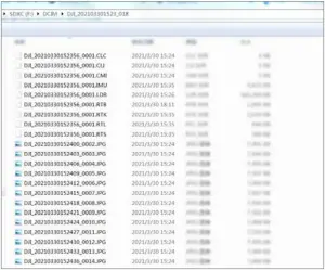
A. The recorded point cloud data is stored in the microSD card. The storage directory is microSD: DCIM/DJI_YYYYMMDDHHMM_NO. _XXX (XXX can be edited by the user).
B. The folder contains not only photos taken during the flight but also files with the suffix CLC, CLI, CMI, IMU, LDR, RTB, RTK, RTL, and RTS.
![]() Chinese characters cannot be used to rename any of the files.
Chinese characters cannot be used to rename any of the files.
Base Station Satellite Data Acquisition
When the mobile network or remote controller video transmission signal is poor, use the RTCM data of the D-RTK 2 Mobile Station or a third-party RTK base station to assist the L1 for data post-processing. Follow the steps below:
- Check the local operation time from the point cloud data file directory stored in the microSD card.
- Search for .DAT format RTCM files of the same time as the stored files of the D-RTK 2 Mobile Station or third-party RTK base station. Rename the file as the same as the .RTB file in the point cloud data file directory and add a .RTCM suffix.
- Copy the .RTCM file to the folder of the point cloud data file directory. DJI Terra will prioritize .RTCM files over .RTB files.
![]()
• Note that the RTCM file stored in the D-RTK 2 Mobile Station is in UTC time format.
• Read the D-RTK 2 Mobile Station User Guide for more information.
Office Data Processing
Users can import the recorded point cloud data into DJI Terra for high-precision model reconstruction. Read the DJI Terra User Manual for more information.
Downloading DJI Terra
DJI Terra is required for data processing. Read the DJI Terra User Manual for more information about how to configure DJI Terra and use reconstruction.
Visit https://www.dji.com/dji-terra/downloads to download and install DJI Terra.
Reconstruction Procedures
Follow the steps below to reconstruct point cloud data in DJI Terra.
- Launch DJI Terra, select New Mission, and create and save a point cloud processing mission.
- Select
 on the mission editing page and import the folder from the microSD card. The folder will be named according to the time the point cloud data was recorded. The folder contains files with the suffix CLC, CLI, CMI, IMU, LDR, RTB, RTK, RTL, and RTS.
 - Configure the point cloud density and output coordinate system settings.
- Click to start reconstruction and wait until it is completed.
- In the reconstruction page, the current mission folder can be opened by pressing “Ctrl+Alt+F” to find the file and check the result of the reconstruction.
- Read the DJI Terra User Manual for more information about how to process data such as optimizing point cloud data accuracy.
LiDAR Point Cloud Description
The L1 features two point cloud scanning methods. Users can choose between non-repetitive and repetitive scanning methods.
A. The non-repetitive scanning method is the L1’s unique LiDAR technology. It provides a near-circular FOV with a scanning density that is denser in the center of the FOV compared to the surrounding area, resulting in a more comprehensive point cloud model.
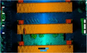
B. The repetitive scanning method provides a flat FOV, which is similar to traditional mechanical scanning methods. It can obtain more uniform and precise scanning results compared to traditional mechanical scanning methods.
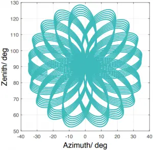
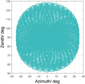
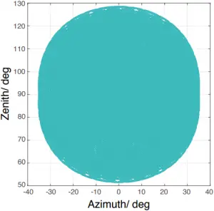
Non-Repetitive Scanning Method
Typical Point Cloud Patterns
For the non-repetitive scanning method, the L1 has a vertical FOV of 77.2° and a horizontal FOV of 70.4°. The figure below displays the typical point cloud patterns of the L1 after 0.1 s, 0.2 s, 0.5 s, and 1 s.
A. Within a radius of 10° of the center of the FOV, the point cloud density rivals traditional 32-line LiDAR sensors within 0.1 s.
B. Within a radius of 10° of the center of the FOV, the point cloud density rivals traditional 64-line LiDAR sensors within 0.2 s. The point cloud density in the rest of the FOV rivals traditional 32-line LiDAR sensors within the same time.
C. Over time, the point cloud density and coverage inside the FOV increase significantly and reveal more detailed information of the surroundings.
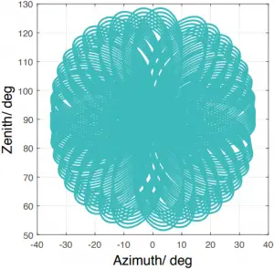
FOV Coverage
The figure below shows the FOV coverage of the L1 compared with non-L1 LiDAR sensors that use traditional mechanical scanning methods.
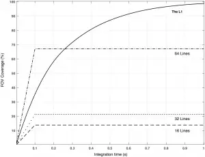
A. When the integration time is less than 0.3 s, the 70% FOV coverage of the L1 is slightly better than a 64-line LiDAR sensor.
B. As the integration time increases, however, the FOV coverage of the L1 increases significantly. After 0.8 s, almost all areas are illuminated by laser beams as the FOV coverage approaches 100%.
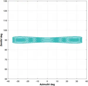
Repetitive Scanning Patterns
For the repetitive scanning method of L1, the scanning repeats approximately every 0.1 s, the horizontal FOV is 70.4°, the vertical FOV is 4.5°, and the vertical angular resolution is slightly better than traditional 32-line LiDAR sensors.
![]()
• Close Proximity Blind Zone: the L1 LiDAR sensor cannot precisely detect objects that are less than 1 meter away. The point cloud data may be distorted to a varying extent when the target object is within a range of 1 to 3 meters.
• The range accuracy of L1 LiDAR is 2 cm tested in an environment at a temperature of 25° C (77° F) with a target object that has a reflectivity of 80% and is 20 meters away from the L1. The actual environment may differ from the testing environment. The figure listed is for reference only.
Maintenance
Exporting Log
Go to the camera view in DJI Pilot, select ![]() , and Export Zenmuse L1 Log to export the camera log to the microSD card of the L1.
, and Export Zenmuse L1 Log to export the camera log to the microSD card of the L1.
Firmware Update
Using DJI Pilot
- Make sure that the L1 is securely mounted onto the aircraft, that there is a strong connection between the aircraft and remote controller and other DJI devices used with the aircraft, and that all devices are powered on.
- Go to HMS in DJI Pilot, select Firmware Update, then Zenmuse L1, and follow the on-screen instructions to update the firmware. Select Update All to update all available devices simultaneously.
Using microSD Card
- Make sure that the L1 is securely mounted onto the aircraft and the aircraft is powered off. Check that there is enough free space on the microSD card and the Intelligent Flight Batteries are fully charged.
- Visit the Zenmuse L1 product page on the DJI official website and go to Downloads.
- Download the latest firmware.
- Once downloaded, copy the firmware file to the root directory of the microSD card.
- Insert the microSD card into the microSD card slot of the L1.
- Power on the aircraft. The gimbal and camera perform an auto-check and will start to update automatically. The gimbal will beep to indicate the status of the firmware update.
- Restart the device after the firmware update is complete.
Update Status Alarm
| Alarm | Descriptions |
| 1 short beep | Firmware update detected. Preparing to update |
| 4 short beeps | Updating firmware. Do not stop update |
| 1 long beep followed by 2 short beeps | Firmware update successful |
| Continuous long beep | Firmware update failed. Try again and contact DJI Support if the problem persists |
![]()
• Make sure that there is only one firmware update file on the microSD card.
• Do not power off the aircraft or detach the gimbal and camera while updating the firmware. It is recommended to delete the firmware update file on the microSD card once the firmware is updated.
Storage, Transportation, and Maintenance
Storage
The storage temperature range for the L1 LiDAR is from -40° to 85° C (-40° to 185° F). Keep L1 LiDAR sensors in a dry and dust-free environment.
- Make sure the L1 LiDAR sensors are not exposed to environments containing poisonous or corrosive gases or materials.
- DO NOT drop the L1 LiDAR sensors and be careful when placing in or taking out of storage.
Transportation
- Before transportation, place the L1 in a suitable box for transportation and make sure it is secure. Make sure to place foam inside the transportation box and that the box is clean and dry.
- DO NOT drop the L1 and be careful when carrying it.
Maintenance
- Under normal circumstances, the only maintenance required for the L1 is to clean the optical window of the LiDAR sensor. Dust and stains on the optical window can negatively affect the performance of the LiDAR sensor. Make sure to regularly clean the optical window to prevent this from happening.
- First, check the surface of the optical window to see if cleaning is necessary. If it is necessary to clean it, follow the steps below:
A. Use compressed or canned air. DO NOT wipe a dusty optical window as it will only cause more damage. Clean the optical window with compressed or canned air before wiping the optical window. It is not necessary to use a wipe if there is no visible stains on the optical window afterward.
B. Wipe the stains: DO NOT wipe using a dry lens tissue as it will scratch the surface of the optical window. Use a wet lens tissue. Wipe slowly to remove the dirt instead of redistributing it on the surface of the optical window. If the optical window is still dirty, a mild soap solution can be used to gently wash the window. Repeat Step B to remove any remaining soap residue.
Specifications
| General | |
| Product name | ZENMUSE L1 |
| Dimensions | 152×110×169 mm |
| Weight | 930±10 g |
| Power | Typical: 30 W; Max: 60 W |
| IP Rating | IP54 |
| Supported Aircraft | Matrice 300 RTK |
| Operating Temperature Range | -20° to 50° C (-4° to 122° F) when using RGB mapping camera: 0° to 50° C (32° to 122° F) |
| Storage Temperature Range | -20° to 60° C (-4° to 140° F) |
| System Performance | |
| Detection Range | 450 m @ 80% reflectivity, 0 klx 190 m @ 10% reflectivity, 100 klx |
| Point Rate | Single return: max. 240,000 pts/s Multiple return: max. 480,000 pts/s |
| System Accuracy (RMS 1σ)* | Horizontal: 10 cm @ 50 m Vertical: 5 cm @ 50 m |
| Real-Time Point Cloud Coloring Coding | Reflectivity, Height, Distance, RGB |
| LiDAR | |
| Ranging Accuracy (RMS 1σ)* | 3 cm @ 100 m |
| Maximum Returns Supported | 3 |
| Scan Modes | Non-repetitive scanning pattern, Repetitive scanning pattern |
| FOV | Non-repetitive scanning pattern: 70.4° (horizontal) × 77.2° (vertical) Repetitive scanning pattern: 70.4° (horizontal) × 4.5° (vertical) |
| Laser Safety | Class 1 (IEC 60825-1:2014) (Eye Safety) |
| Inertial Navigation System | |
| IMU Update Frequency | 200 Hz |
| Accelerometer Range | ±8 g |
| Angular Velocity Meter Range | ±2000 dps |
| Yaw Accuracy (RMS 1σ)* | Real-time: 0.3°, Post-processing: 0.15° |
| Pitch/Roll Accuracy (RMS 1σ)* | Real-time: 0.05°, Post-processing: 0.025° |
| Auxiliary Positioning Vision Sensor | |
| Resolution | 1280×960 |
| FOV | 95° |
| RGB Mapping Camera | |
| Sensor Size | 1 in |
| Effective Pixels | 20 MP |
| Photo Size | 5472×3078 (16:9), 4864×3648 (4:3), 5472×3648 (3:2) |
| Focal Length | 8.8/24 mm (equivalent) |
| Shutter Speed | Mechanical shutter speed: 1/2000-8 s Electronic shutter speed: 1/8000-8 s |
| ISO | Video: 100-3200 (auto), 100-6400 (manual) Photo: 100-3200 (auto), 100-12800 (manual) |
| Aperture Range | f/2.8 – f/11 |
| Supported File System | FAT (≤32 GB); exFAT (>32 GB) |
| Photo Format | JPEG |
| Video Format | MOV, MP4 |
| Video Resolution | H.264, 4K: 3840×2160 30p |
| Gimbal | |
| Stabilized System | 3-axis (tilt, roll, pan) |
| Angular Vibration Range | ±0.01° |
| Mount | Detachable DJI SKYPORT |
| Controllable Range | Tilt: -120° to +30°, Pan: ±320° |
| Operation Modes | Follow/Free/Re-center |
| Data Storage | |
| Raw Data Storage | Photo/IMU/Point cloud/GNSS/Calibration files |
| Supported microSD Cards | microSD: Sequential writing speed 50 MB/s or above and UHS-I Speed Grade 3 rating or above; Max capacity: 256 GB |
| Recommended microSD Cards** | SanDisk Extreme 128GB UHS-I Speed Grade 3 SanDisk Extreme 64GB UHS-I Speed Grade 3 SanDisk Extreme 32GB UHS-I Speed Grade 3 SanDisk Extreme 16GB UHS-I Speed Grade 3 Lexar 1066x 128GB U3 Samsung EVO Plus 128GB |
| Post-Processing Software | |
| Supported Software | DJI Terra |
| Data Format | DJI Terra supports exporting standard format point cloud models: Point cloud format: PNTS/LAS/PLY/PCD/S3MB |
* The accuracy was measured under the following conditions in a DJI laboratory environment: after a 5-minute warm up, using Mapping Mission with Calibration Flight enabled in DJI Pilot, and with the RTK in FIX status. The relative altitude was set to 50 m, flight speed to 10 m/s, gimbal pitch to -90°, and each straight segment of the flight route was less than 1000 m. DJI Terra was used for post-processing.
** The recommended microSD cards may be updated in future. Visit the DJI official website for the latest information.

WE ARE HERE FOR YOU

Contact DJI SUPPORT
via Facebook Messenger
This content is subject to change.

Download the latest version from
http://www.dji.com/zenmuse-l1
If you have any questions about this document, please contact DJI by sending a message to [email protected].
ZENMUSE is a trademark of DJI.
Copyright © 2021 DJI All Rights Reserved.


