mXion DGK 1-Channel Radio Feedback Module
Introduction
Dear customer, we strongly recommend that you read these manuals and the warning notes thoroughly before installing and operating your device. The device is not a toy (15+).
NOTE: Make sure that the outputs are set to appropriate value before hooking up any other device. We can’t be responsible For any damage if this is disregarded.
General information
We recommend studying this manual thoroughly before installing and operating your new device.
NOTE: Some functions are only available with the latest firmware. Please make sure that your device is programmed with the latest firmware.
Summary of Funktions
Train detection module for PC controlling Control commands without PC
DC/AC/DCC operation all kind of voltage Analog and digital operation with all systems Automatic processes can be make
Ideally for automatic function for 30Z
Fully weatherproof module
Wireless feedback module with included reed switch
CV programming (CV, Register, Bitwise, POM) POM programming (Loco and switch)
Radio feedback easily
Scope of supply
Manual
mXion DGK
Hook-Up
Install your device in compliance with the connecting diagrams in this manual. The device is protected against shorts and excessive loads. However, in case of a connection error e.g. a short this safety feature can’t work and the device will be destroyed subsequently.
Make sure that there is no short circuit caused by the mounting screws or metal.
Product description
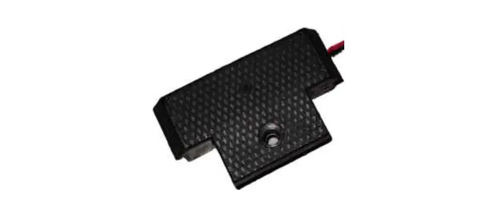
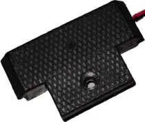
The mXion DGK is a universal, analog and digital (any format/system) usable occupancy detector for the detection of electricity consumers within a section.
The special thing about the DGK ist hat it is fully encapsulated electronics in a small case whichh ideally placed in the LGB track. The DGK includes a full-fledged decoder and a reed contact which from the outside can be triggered by a magnet. By the integrated radio module can then be a switching command for turnouts or a feedback address sent to the control center become. Thanks to the separate radio channel this is particularly strong and secure. This eliminates the need for a lot of cabling and the feedback can be used there where they are needed.
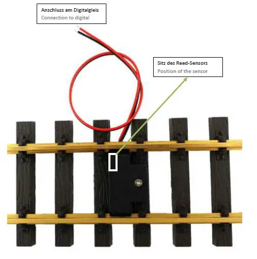
Connection
Only the 2 cables need to be connected to the digital track be connected. Put the DGK between the track and screw this with the screw firmly. Finished!
The integrated reed switch can be triggered by train magnet.
Pay attention to the magnet/sensor (see image) The module needs 2 sec. to start first after that it can be addressed via magnets. Note you also set the default delay time.
Wireless connection
The DGK has a built-in radio module which preset on our central MZSpro and 30Z is.
It is important that the radio channel is identical to that is set in the control center. Via CV10 can check whether the radio module starts properly.
Level controlling
Each close a contact in mode switch control level dependent switches the associated one in the address CV entered turnout address to right each open to the left. The direction is invertible via CV. So that can be set up simple control panels.
Train detection mode
Upon delivery, all contact inputs are open occupancy report made (mode 2). This mode is meant for trains and their position on recognizing the system and using a PC control.
Settings and programming
The module settings are made via DCC by means of a programming track or via POM.
Calculation contact addresses
The contact addresses are equivalent to calculating turnout addresses (see POM address). Depending on the mode is the address a turnout or
feedback address.
Example: You concern contact address < 256:
Enter the different address in CV „low“ and CV „high“ will always be 0.
Example: You convern contact address 1250: Address CV high: 1250 / 256 = 4,88 High: 4 Address CV low: 1250 – (Address high * 256) = 1250 – (4 * 256) = 226.
CV-Table
| CV | Beschreibung | S | W | Bereich | Bemerkung | |
| 1 | Feedback address HIGH | 0 1 | 1 – 2048 | Feedback address If <256 enter in CV2 | ||
| 2 | Feedback address LOW | |||||
| 3 | Delay time ON | 0 | 0 – 255 | 0,1 sek / value | ||
| 4 | Delay time OFF | 0 | 0 – 255 | 0,1 sek / value | ||
| 5 | Send retries | 0 | 0 – 255 | Send repetitions, 1ms / value | ||
| 6 | Mode | 2 | 0 – 2 | 0 = feedback (report turnout address) 1 = switch command 2 = occupancy detector | ||
| 7 | Software version | – | – | only readable (10 = 1.0) | ||
| 7 | Decoder reset functions | |||||
| 2 Reset ranges selectable | 11 16 | Module is completely reset Programming lock | ||||
| 8 | Manufacturer ID | 160 | – | read only | ||
| 7+8 | Register programming mode | |||||
| Reg8 = CV-Address Reg7 = CV-Value | CV 7/8 keep their value First write the target address to CV 8, then write or read CV 7 with a value (e.g. CV 19 should have 3) Send CV 8 = 19, CV 7 = 3 | |||||
| 9 | Radio ID | 165 | 0 – 255 | Radio ID for feedback | ||
| 10 | Radio error | 0 | 0/1 | 0 = faulty radio module, 1 = OK | ||
| 11 | Radio channel | 0 | 0 – 255 | Radio channel | ||
| 15 | Programming lock (lock) | 85 | 0 – 255 | Only change this to lock | ||
| 16 | Programming lock (lock) | 85 | 0 – 255 | Change here changes CV 15 | ||
| 18 | Turnout address calculation | 0 | 0/1 | 0 = turnout address according to standard 1 = turnout address like Roco, Fleischmann | ||
| 19 | Switching command inverse | 0 | 0/1 | 0 = normal, 1 = invers | ||
| 20 | POM address high | 4 | 1 – 2048 | POM programming address switch module (standard 2048) | ||
| 21 | POM address low | 0 | ||||
Technical data
- Power supply:
7-27V DC/DCC
5-18V AC - Current:
20mA - Temperature range:
-20 up to 80°C - Dimensions L*B*H (cm):
1.4*4.5*3.5
NOTE: In case you intend to utilize this device below freezing temperatures, make sure it was stored in a heated environment before operation to prevent the generation of condensed water. During operation is sufficient to prevent condensed water.
Warranty, Service, Support
micron-dynamics warrants this product against defects in materials and workmanship for one year from the original date of purchase. Other countries might have different legal warranty situations. Normal wear and tear, consumer modifications as well as improper use or installation are not covered. Peripheral component damage is not covered by this warranty. Valid warrants claims will be serviced without charge within the warranty period. For warranty service please return the product to the manufacturer. Return shipping charges are not covered by micron-dynamics. Please include your proof of purchase with the returned good. Please check our website for up to date brochures, product information, documentation and software updates. Software updates you can do with our updater or you can send us the product, we update for you free.
Errors and changes excepted.
Hotline
For technical support and schematics for application examples contact:
micron-dynamics
[email protected]
[email protected]
www.micron-dynamics.de
https://www.youtube.com/@micron-dynamics.


