 Ditec 0DT848 Sector Reset
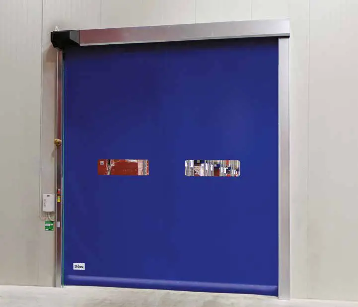
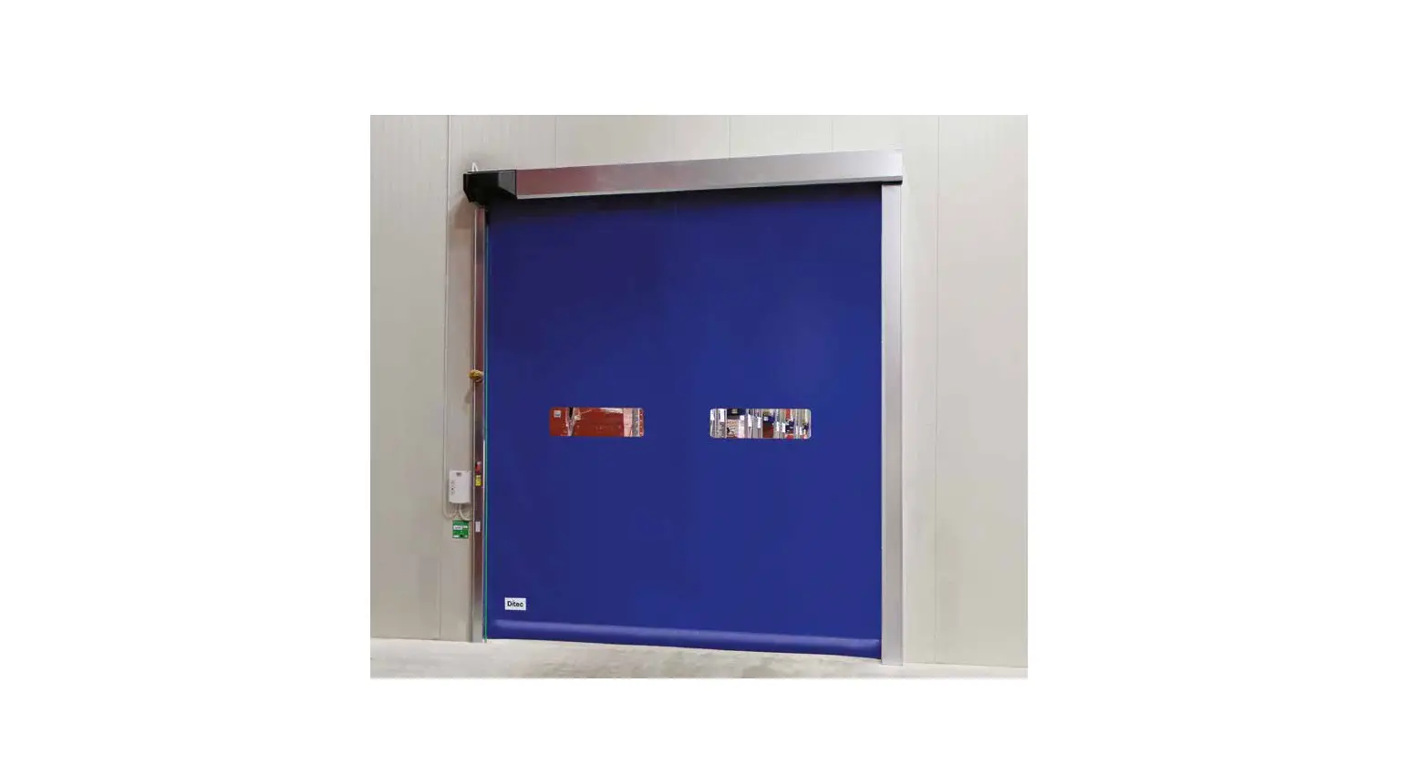
Ditec Sector Reset
Product Information
- The Ditec Sector Reset is a motorized industrial door designed for installation in various commercial and industrial applications.
- The door can be installed to control access to enclosed spaces, such as warehouses or loading docks, and can be operated using an electronic control panel or a remote control.
- The door can be customized according to specific user requirements with a range of safety features, such as safety photocells and a safety edge system.
- The door is equipped with a linearity encoder system that ensures smooth and safe operation of the door.
- The door is powered by an inverter motor that allows for precise control over the opening and closing speed of the door.
Product Usage Instructions
Before installing and using the Ditec Sector Reset, please read through the user manual carefully and ensure that all safety warnings and guidelines are followed.
- Begin with the installation of the mechanical components, such as the vertical pillars, crossbeam, counterweights, and canvas placement. Follow the recommended installation steps provided in the user manual.
- After completing the mechanical installation, proceed with the electrical connections by setting up the electrical control panel and connecting it to the motor and safety systems. Please refer to the wiring diagram provided in the user manual for guidance.
- To operate the door, use the electronic control panel or remote control. Follow the instructions provided in the user manual for proper use of these devices.
- When not in use, ensure that the door is securely closed and locked to prevent unauthorized access.
- Regular maintenance and inspection of the Ditec Sector Reset is recommended to ensure optimal performance and safety. Please refer to the maintenance guidelines in the user manual for more information.
MECHANICAL INSTALLATION DRAWINGS
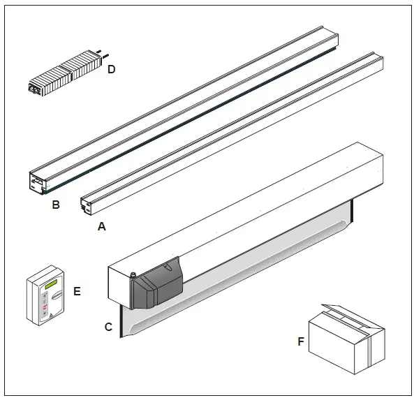
PACKING LIST
| Reference | Description | Quantity |
| A | Left column | 1 |
| B | Right column | 1 |
| C | Transom with rolled curtain | 1 |
| D | Counterweight | 1 |
| E | Control unit | 1 |
| F | Hardware box | 1 |
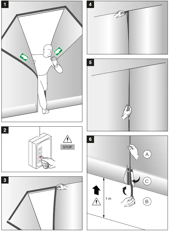
EMERGENCY EXIT – RESTORE CURTAIN INSTRUCTION
GENERAL SAFETY PRECAUTIONS
- This installation manual is intended for professionally competent personnel only. The installation, the electrical connections and the settings must be completed in conformity with good workmanship and with the laws in force.
- Read the instructions carefully before beginning to install the product. Incorrect installation may be a source of danger. Packaging materials (plastics, polystyrene, etc) must not be allowed to litter the environment and must be kept out of the reach of children for whom they may be a source of danger. Before beginning the installation check that the product is in perfect condition.
- Do not install the product in explosive areas and atmospheres: the presence of flammable gas or fumes represents a serious threat to safety.
- Before installing the door, make all the structural modifications necessary in order to create safety clearance and to guard or isolate all the compression, shearing, trapping, and general danger areas.
- Check that the existing structure has the necessary strength and stability.
- The safety devices must protect against compression, shearing, trapping and general danger areas of the motorized door.
- Display the signs required by law to identify danger areas. Each installation must bear a visible indication of the data identifying the motorized door.
- Before connecting to the mains check that the rating is correct for the destination power requirements.
A multipolar isolation switch with minimum contact gaps of 3 mm must be included in the main supply. - Check that upstream of the electrical installation there is an adequate differential switch and a suitable circuit breaker. Ensure that the motorized door has an earth terminal in accordance with the safety adjustments in force.
- The manufacturer of the door declines all responsibility in cases where components are incompatible with the safe and correct operation of the product only original spare parts must be used or whenever modifications of any nature are made that have not been specifically authorized by the manufacturer.
- For repairs or replacements of products, only Ditec’s original spare parts must be used.
- The fitter must supply all information concerning the automatic, manual, and emergency operation of the motorized door or gate, and must provide the user the device with the operating instructions.
All right reserved
All data and specifications have been drawn up and checked with the greatest care. The manufacturer cannot however take any responsibility for eventual errors, ommisions or incomplete data due to technical or illustrative purposes.
Parts Description
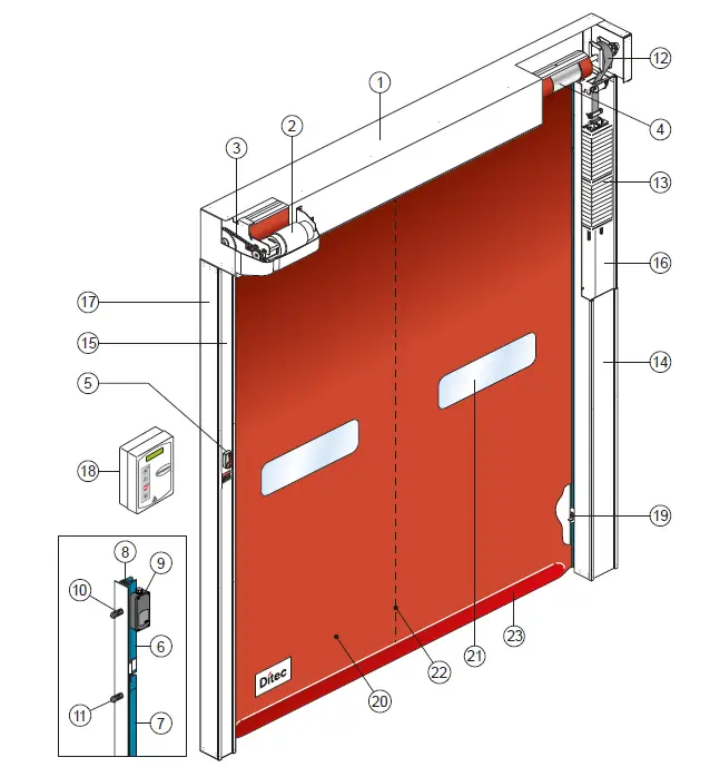
- Transom
- Motor K10
- Transmission chain
- Rolling shaft
- Manual release lever
- Polyzene guide upper section
- Polyzene guide lower section
- Fixing plate of the guide
- Linear Encoder (SLE)
- Supporting spring
- Fixing screw
- Belt counterweight
- Modular counterweight
- Right column cover
- Left column cover
- Right column
- Left column
- Electronic board
- Photocell 5FB
- Polyester curtain
- PVC transparent window
- Vertical re-reinforcing strips
- Bottom edge with sand ballast
TECHNICAL CHARACTERISTICS
CONTROL PANEL TRIPHASE (49E)
- Power supply voltage ………….400 V triphase 50/60 Hz
- Line sizing ……………………………………………………… 5 A
- Auxiliary control power voltage…………………….24V
- Motor rating………………………………………………0,9 KW
- Control board protection class……………………….. IP 55
- Operating temperature…………………………. – 5 + 50 °C
- Power supply voltage ……… 230 V monophase 50/60 Hz
- Line sizing ……………………………………………………. 12 A
- Auxiliary control power voltage…………………….24V
- Motor rating………………………………………………0,9 KW
- Control board protection class……………………….. IP 55
- Operating temperature…………………………. – 5 + 50 °C
Correctly size the line conductor cross-section by referring to the indicated absorption and taking the length and installation of the cables into account.
MECHANICAL INSTALLATION
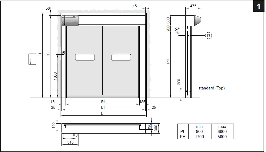
Checking the opening (fig.1).
- Check the dimensions of the opening, and their correspondence to the overall dimensions of the door supplied, taking into consideration any necessary tolerances in the case of installation in an archway.
- Check that no existing structures obstruct the assembly of the door.
- Ensure the resting surfaces are level and, if necessary, adapt them using appropriate shims.
- Check the solidity of the opening: secure anchorage must be ensured by means of brackets or anchor plugs. In the case of insufficient or dubious solidity, it is necessary to create an adequate self-supporting metal structure.
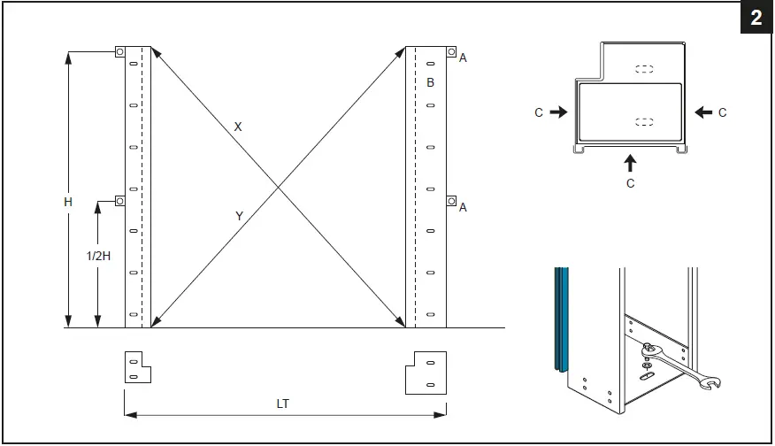
Fitting the uprights (fig.2).
- Measure the overall dimensions of the crosspiece (LT).
- Mark the exact position of the uprights on the floor.
- Remove the covers of the uprights and fix the bases according to the marks using special M8 size plugs.
- Plumb the uprights and fix them at the indicated points (A) with external brackets or (B) for fixing from inside column. M8 size plugs.
- Check that the installation is perfectly perpendicular by measuring the diagonals.
Do not drill holes in the right-hand upright near the counterweight sliding area (C).
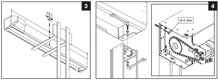
Assembling the crosspiece
- Remove the M8 bolts preassembled on the ends of the crosspiece.
- Carefully lift the crosspiece using a forklift truck or other lifting equipment. Make sure that it cannot fall while being lifted and protect the door section from being damaged (fig.3).
- Place the crosspiece on the uprights, reinsert the fixing bolts and tighten them (fig.4).
Fix the crosspiece onto the side plate. - For doors with PL > 4000 fix the crosspiece on the centre (to avoid unsightly bending of the frame).
Assembling the counterweights
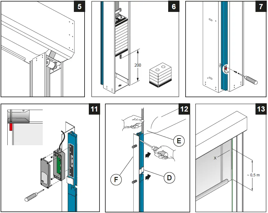
- Completely unroll the belt leaving 1 spare turn wound around the winding drum and passing the belt around the transmission pulley (fig.5).
- Fix the belt in place using the special plaque (fig.6). Adjust the length of the belt so that the threaded bar remains approximately 200 mm off the ground (when the door is wide open).
- Finely adjust the balance using the 4 lower counterweight elements.
Installing the photocells
- Connect the photocells as shown in (fig.16).
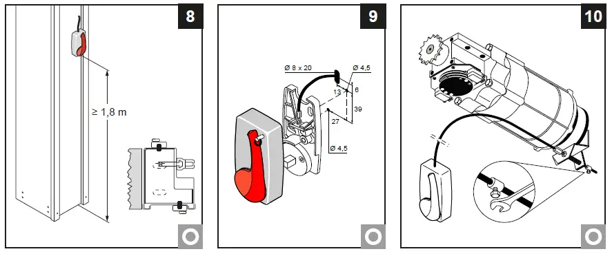
Assembling the emergency release lever
- The emergency release lever must be assembled on the structure itself or on the wall at a minimum height of 1.8 m off the ground (fig.8).
- If it is assembled on the structure, use the measurements indicated in (fig.9) and place the drive cable in the spaces and connect it to the gearmotor brake (fig.10).
- Check that the device is operating correctly; when the lever is operated, the door section should be free to rise.
Installation of the Safety Linear Encoder (SLE)
- The SLE must be fixed to the sliding guide of the flexible door on the left side as shown in (fig.11) and connected as shown at the paragraph 5.
Positioning the curtain
- Close the upper part of the plastic guides (D) by pushing on the outer side (fig.12)
- Insert each tooth side edge (E) of the curtain in the relevant guide, if necessary to make easier the operation remove the higher screw (F).
- Roll down the curtain so the bottom edge is 0.5m beneath the curtain inlet slot (fig.13).
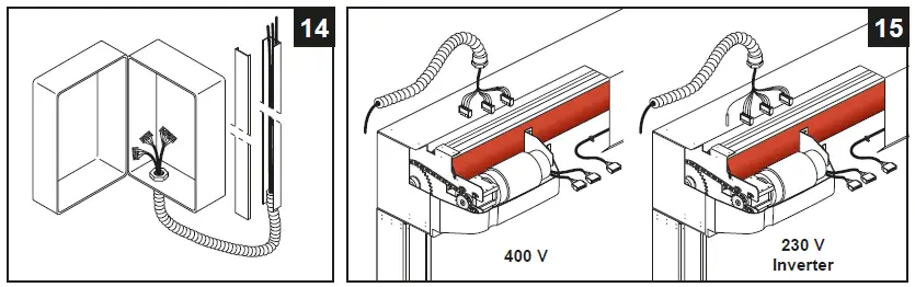
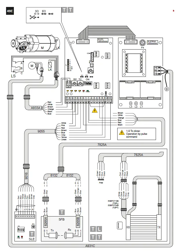
ELECTRICAL CONNECTIONS
Electrical panel
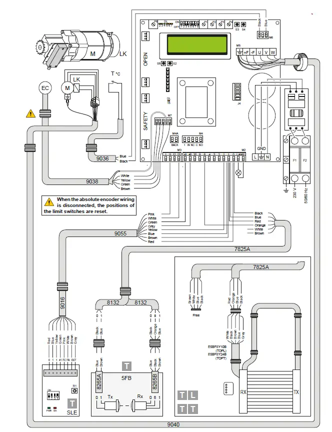
- Insert the cables with the pre-wired terminal boards in the housing (fig. 14) and connect them to the boards (as shown in chap. 5). Fit the cables in the conduit and connect the connectors on the motor (fig.15).
Cabling connection on the board must be done with main power cut off, for at least 30 sec.
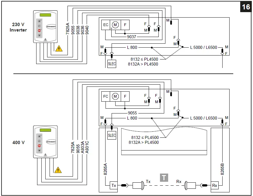
Electrical panel/motor/safety device connections
- Figure 16 shows the layout of the cables supplied and their position in the door; each cable is identified by a special code on an adhesive label.
Safety photocells
- • Make the electrical connections as shown in (fig.16).
• Make the connections in the control panel as shown in the diagrams in chap. 5.

Correctly size the line conductor cross-section by referring to the indicated absorption and taking the length and installation of the cables into account.
49E ELECTRONIC CONTROL PANEL – CONNECTIONS
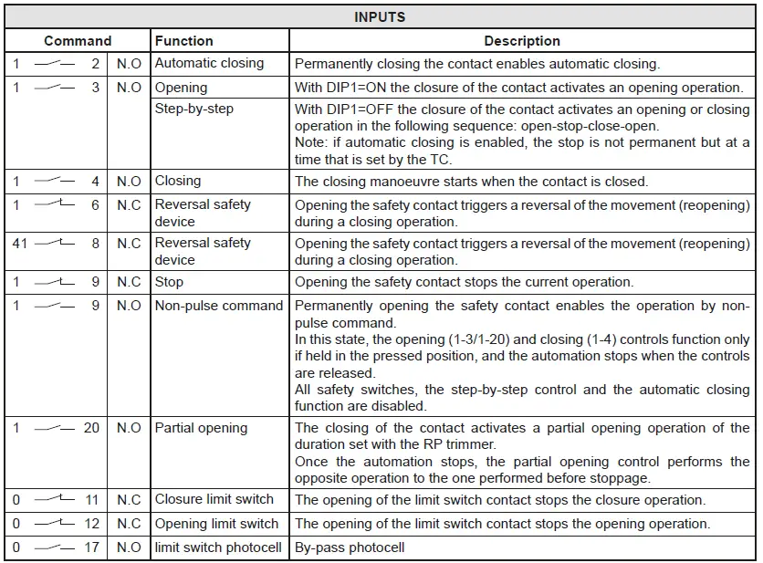
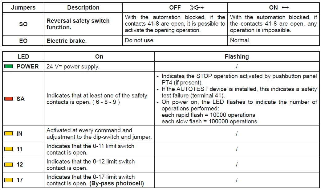
SIGNALS AND SETTING
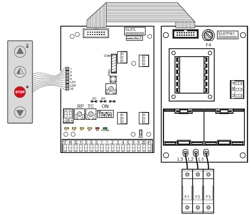
| FUSES | |||
| ID | Value | Dimension | Circuit |
| F1 – F2 – F3 | 8A – 500V | 10.3 x 38 | Three phase line |
| F4 | 3.15A – 230V | 5 x 20 | Transformer |
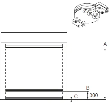
ADJUSTMENT LIMIT SWITCH
- Activate the door by pressing the appropriate buttons, and check it moves in the correct direction and If necessary, reverse the movement direction by modifying the phase sequence, adjusting the line wires upstream of the main switch.

- Carry the curtain in the closed position.
- By means of a screwdriver, turn the “C” cam until the relative micro-switch is triggered.
- Carry out the same procedure for the opening limit switch: bring the curtain to the open door position, and adjust cam “A”.
- Carry out the same procedure for the opening limit switch: bring the curtain at 300mm from the ground, and adjust cam “B”.
- Activate the automation to check the calibration and, if necessary, make a further adjustment.
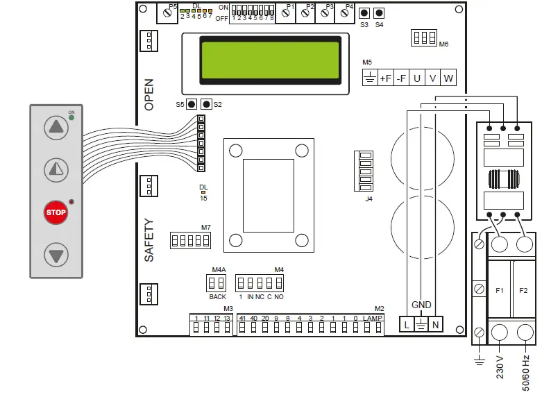
52E CONTROL PANEL (INVERTER) – Connections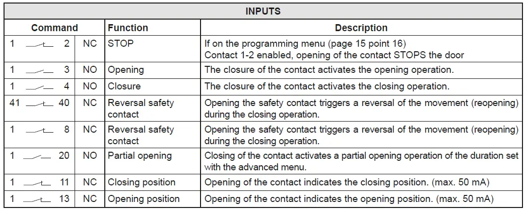
CONTROL PANEL CONNECTORS
| M2 | Safety device / Commands |
| M3 | Position signal |
| M4 | Interlock |
| M4A | Back |
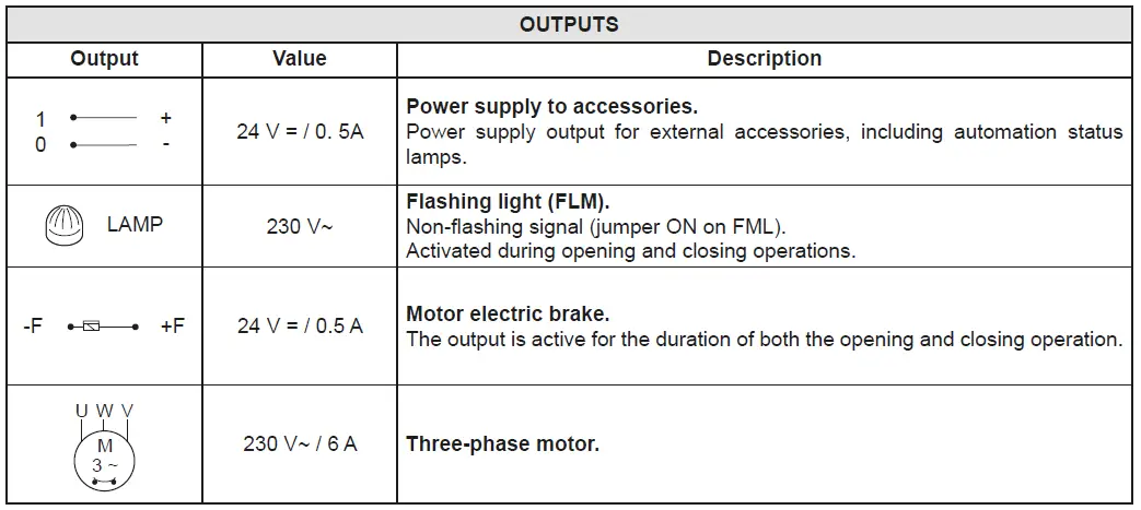
| M5 | Motor / brake motor |
| M6 | Thermal motor |
| M7 | Absolute encoder |
| J4 | Brake resistance |
| OPEN | Auxiliary panel card |
| SAFETY | Auxiliary safety card |
ADJUSTMENTS AND SIGNALS 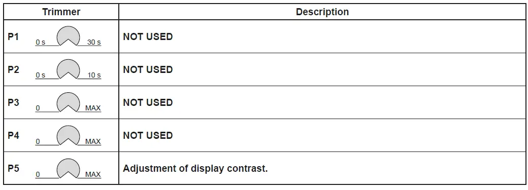
| Dip-switches | Description | OFF | ON |
| DIP 1 | Future use | – | – |
| DIP 2 | Access to advanced menu | Disabled. | Enabled |
| DIP 3 | Trimmer enabling | Disabled | Enabled |
| DIP 4 | Counter TOT: Number of operations SVC: Number of operations left until service | Disabled | Enabled |
| DIP 5 | Access to the service menu | Disabled | Enabled |
| DIP 6 | Door operating data display (F working, I Bus, I peak, V Bus) | Disabled | Enabled |
| DIP 7 | Future use | – | – |
| DIP 8 | Cyclic operation menu | Disabled | Enabled |
| LED | On |
| DL2 | Closing position |
| DL3 | Deceleration |
| DL6 | Partial opening |
| DL7 | Opening position |
| DL15 | Autostart |
| Buttons | Description |
| S2 | USED FOR PROGRAMMING |
| S3 | NOT USED |
| S4 | NOT USED |
| S5 | USED FOR PROGRAMMING |
| FUSES | |||
| ID | Value | Size | Circuit |
| F1 – F2 | 12A – 500V | 10.3 x 38 | Single phase line |
POSITION ADJUSTMENT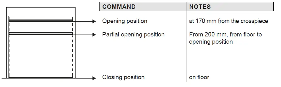
TROUBLESHOOTING
| Display message | Problem | Check |
| Current limit exceeded | Requested motor torque exceeds available torque. | • Reduce opening speed. • Check power supply. • Check power supply wiring. |
| Encoder battery | Absolute encoder battery flat or position read error | • Switch off the control panel, wait 3 minutes and reconnect the power supply. If the problem is not resolved, try again. • If the encoder battery message remains displayed, replace the encoder. |
| Insert brake resistance | Voltage on BUS exceeds threshold | • Switch off the control panel, wait 3 minutes and reconnect the power supply. • If the error reoccurs, check that the voltage on the BUS is lower than 360 V. |
| Max. BUS voltage | BUS voltage exceeds threshold | • Switch off the control panel, wait 3 minutes and reconnect the power supply. • Check the control panel power supply voltage. |
Installation menu
When the control panel is switched on, after showing the messages DITEC and microprocessor and card FW VERSION, the device automatically enters the installation menu and displays the message SELECT LANGUAGE.
Confirm with![]()
Remove cables from PIN 3, 4, 20 during programming
| STEP | 1st level options | 2nd level options | Menu scrolling | Notes |
| 1 | Select language |
| Confirm with: | |
| Confirm with:
| ENGLISH | |||
| ITALIAN | ||||
| FRANÇAIS | ||||
| DEUTCH | ||||
| ESPANOL – POLSKA CESKY – MAGYAR | ||||
| 2 | Door model |
| Confirm with: | |
| Confirm with:
| SOFT RESET | |||
| SECTOR RESET | ||||
| SMART PLUS | ||||
| SECTOR PLUS | ||||
| TRAFFIC C | ||||
| SMART RESET | ||||
| 3 | Position control |
| Confirm with: | |
| Confirm with:
| LIMIT SWITCH | |||
| ENCODER | ||||
| 4 | Calibrating positions |
| The door will move to the desired position in man present mode and at low speed.
Confirm position with: | |
| Confirm with:
| CLOSED POSITION | |||
| PARTIAL OPEN POS. | ||||
| OPEN POSITION | ||||
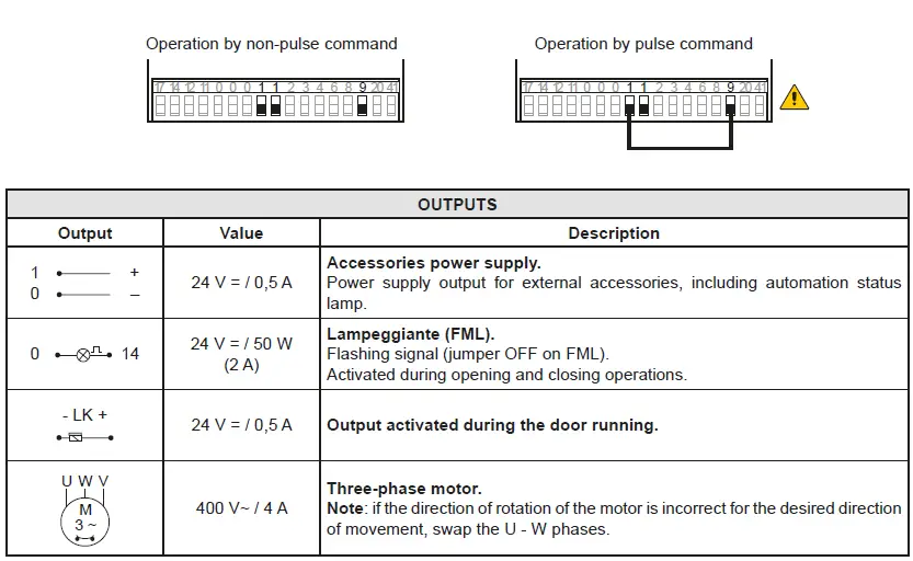
| 5 | Command mode |
| Confirm with: Selecting 1-9: if 1-9 is closed, the command mode will be impulsive, if 1-9 is open the command mode will be “dead man” | |
| Confirm with:
| IMPULSIVE | |||
| MAN PRESENT | ||||
| INPUT 1-9 | ||||
| 6 | CONFIRM DATA | Confirm with: |
PROGRAMMING COMPLETED
The door is now programmed and operating with the set default speed values. With the door MOVING, the voltage and current values will be displayed on the BUS.
Advanced menu
The advanced menu allows you to modify the position of the limit switches which have previously been set and modify the set default parameters.
To access the Advanced Menu:
- STOP the door
- Set DIP 2 to ON
“ENCODER CALIB.”, the first item in the advanced menu, will appear on the display.
ONCE PROGRAMMING HAS ENDED, SET DIP2 TO OFF
Remove cables from PIN 3, 4, 20 during programming
| STEP | 1st level options | Scrolling | Confirm | 2nd level options | Notes |
| 1 | Encoder Calibration |
|
| Closed position |
| The door will move to the desired position in man present mode and at low speed. All the positions (closing, partial opening, opening) must be set. |
| 2 | Photocell excluded (step present only for Reset doors) |
| Change value (1 unit @ 3mm) |
| By increasing the value, the position of the photocell by-pass is raised | |
| 3 | Primary safety device excluded |
| Change value (1 unit @ 3mm) |
| By increasing the value, the position of the primary safety by- pass is raised | |
| 4 | Automatic closing (default SI with T= 5 s) |
|
| YES |
| |
| NO | ||||||
| 5 | Automatic closing time |
| Time variant |
| Option available only if YES has been selected for point 4). Value ranging from 0 to 100 sec. | |
| 6 | Command mode |
|
| Impulsive |
| Selecting 1-9: if 1-9 is closed, the command mode will be impulsive, if 1-9 is open the command mode will be “dead man” |
| Man present | ||||||
| INPUT 1-9 | ||||||
| 7 | Opening safety device |
|
| YES |
| If set to YES, the closed door that receives an opening command does not open if the photocell is activated. |
| NO | ||||||
| 8 | Interlock |
|
| NO INTERLOCK |
| AIRLOCK: door 2 opens with ex- ternal command only if door 1 is closed.
INTERLOCK: door 2 opens auto- matically when door 1 has closed |
| AIRLOCK | ||||||
| INTERLOCK | ||||||
| 9 | Pre-flashing when opening (default no) |
|
| YES |
| Pre-flashing has a set time of 3 sec. |
| NO | ||||||
| 10 | Opening ramp advance |
| CHANGE VALUE (1 unit @ 3mm) |
| When the value increases, the deceleration distance when opening increases. | |
| 11 | Opening speed in (Hz) |
|
| CHANGE VALUE |
| The setting of values that are higher than the default ones must be assessed according to door dimensions and operating conditions. |
| 12 | Closing speed in (Hz) |
| CHANGE VALUE |
| The setting of higher values must be assessed according to door dimensions and operating conditions. | |
| 13 | Enable service alarms |
|
| YES |
| |
| NO | ||||||
| RESET? | Restart the service count down | |||||
| 14 | Service thresh |
| CHANGE VALUE |
| Option available only if YES has been selected for point 14). Set value to steps of 1000 cycles Max 200,000 cycles | |
| 15 | Enable stop 1-2 |
|
| YES |
| If set to YES, opening of the contact 1-2 STOPS the door. |
| NO | ||||||
| 16 | Brake resistance (default NO) |
|
| YES |
| Set to YES when the door is supplied with brake resistance. |
| NO | ||||||
| 17 | PARAMETER RESET |
| CONFIRM |
| Confirm to go back to the installation menu. |
ONCE PROGRAMMING HAS ENDED, SET DIP2 TO OFF
Timed opening menu
With door in STOP position and DIP 8 ON you enter the menu CYCLIC MODE. By activating this mode it is possible to set a timed opening at regular time intervals. Once the mode is set put DIP 8 OFF.
| STEP | 1st level options | Scrolling | Confirm | 2nd level options | Notes |
| 1 | CYCLIC MODE |
|
| TIMER OFF |
| Timer not active |
| TIMER ON | Timer active | |||||
| 2 | TIME UNIT |
|
| MIN. |
| Timer by minuts |
| SEC. | Timer by seconds | |||||
| 3 | OPENING TIME |
| 1 …200 |
| Set the regular time intervals | |
| 4 | AUTO CLOS.TIME |
| 1….200 |
| Set the time during which the door remains open | |
| 5 | TOT |
| VALUE |
| Cycle counter | |
| 6 | RESET CYCLES |
| RESET? |
| Cycle counter reset |
When CYCLIC MODE is active, the display shows every 2 sec: TOT cycle – count down to next open/OPENING TIME
Service menu (password required)
The Service menu is used to modify the brake resistance thresholds, the overcurrent threshold and the anti-wind function when the encoder intervenes.
To access the Service menu:
- STOP the door
- Set DIP5 to ON
- Enter the PW: button sequence OPEN- OPEN- CLOSE- PARTIAL OPENING
Remove cables from PIN 3, 4, 20 during programming
| 1 | MIN BRAKING VOLT. Default 340Vdc | Threshold for partial intervention of braking resistance |
| 2 | MAX BRAKING VOLT. Default 380Vdc | Threshold for total intervention of braking resistance |
| 3 | OVERCURRENT LIMIT Default 10A | If the current on the BUS exceeds the set threshold, the door opens at half the speed to reduce absorption. |
| 4 | RAMP SLOPE DURING OPENING | Changes the slope of the deceleration ramp when opening. Default 15. (If the value is increased, the ramp distance is reduced). |
| 5 | BATTERY LEVEL | Visualizes the encoder battery charge level from 0% to 100% |
| 6 | ALARM LIST | The last 50 alarms are displayed: Overcurrent; bus voltage exceeds limit, Intervention of brake resistance, inverter overtemperature, faulty motor driver (encoder). To exit, press partial opening |
ONCE PROGRAMMING HAS ENDED, SET DIP5 TO OFF
Display messages
| Ditec | door closed waiting for command | |
| Opening of VBUS IBUS | door opening | |
| Door open – automatic closing time | Door open | |
| Closing of VBUS IBUS | door closing | |
| Input 40 closed; input 8 open | intervention of photocell | When door is moving |
| input 40 open; input 8 closed | intervention of encoder (SLE) | When door is moving |
| Thermal or release micro open | Intervention of safety micro on manual opening device / intervention of motor thermal switch. | |
| Opening safety device activated | photocell engaged when door is closed and door does not open | Message that only appears if the “opening safety” function is set to YES on the advanced menu (step 7). |
| Door stopped | stop command activated |
Interlock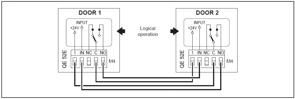
ADJUSTING AND STARTING
Adjustment of the Safety Linear Encoder (SLE)
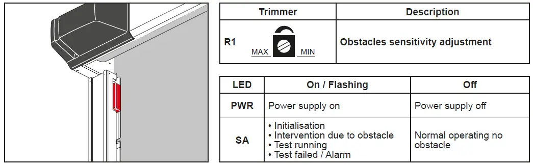
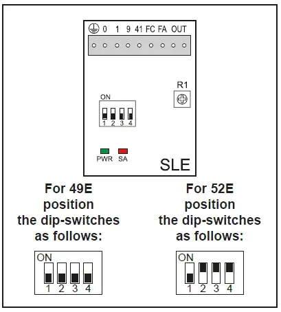
| Dip- switches | Description | OFF | ON |
| DIP 1 | Control panel type | 49E / 52E | / |
|
DIP 2 | Obstacle detected after FC closing limit switch |
Disabled | Enabled (only control panels with INVERTER) |
| DIP 3 | Scale of sensitivity | HIGH (doors close quickly) | LOW (doors close slowly) |
|
DIP 4 | Limit switch polarity | 0 = Limit switch common 49E | 1 = Limit switch common 52E) |
TROUBLESHOOTING
DANGER: Before performing and operations and working on the electronic equipment make sure that the power supply has been disconnected
WARNING: The following instructions are for qualified and authorised personnel only. Specific laws and standards must always be complied with even when not expressly indicated.
For repair work or replacements, use only original Ditec spare parts.
| COMMAND | PROBLEM | CHECK |
| Any command with the curtain in any position | The curtain and the motor do not move | • Mains power supply or fuses F1, F2, F3 • STOP activated (“Stop” LED on push-button panel permanently on) • Motor connected to wrong terminals and/or for 400V version dip-switch in incorrect position (see page 8) • For 400V version opening (A) and closing (C) limit switches activated simultaneously (LEDs 11 e 12 on) • Motor with thermal switch activated • Manual operation safety micro activated • One of the power devices faulty (control panel, motor, motor connection cable) |
| The motor rotates in the opposite direction | • Invert the position of the two phases of the power supply line | |
| Opening command with curtain closed | The motor does not move | • Opening command not connected correctly or faulty (commands 1 – 3) • For 400V version safety device activated (Stop button LED flashing and SA LED permanently ON) with SO jumper closed • Opening limit switch(A) activated (LED 12 ON) • Closing command always activated or short-circuited |
| Closing command with curtain open | The motor does not move | • Closing command not connected correctly or faulty (commands 1 – 4) • Safety device activated (Stop button LED flashing) • Closing limit switch (C) activated (LED 11 ON) • Opening command always activated or short-circuited • Failed safety device autotest (Stop LED on push-button panel OFF) |
| Stop activated during an operation | The motor does not stop | • Stop command not working or incorrectly connected (Stop LED on push-button panel does not come on) |
| The motor stops late | • Motor brake worn or faulty | |
| Activation of a safety device during closing | Door movement is not reversed | • Safety device faulty or not connected correctly • Check earth connections. |
| Door movement does not reverse or reverses only for part of the stroke | For 400V version • Input 17 closed (LED 17 OFF) • Cam B incorrectly regulated (LED 17 OFF or comes on in an incorrect position) | |
| Automatic closure activated with curtain open | The door does not close automatically after the time set with TC | • Automatic closure not enabled correctly • Opening command always activated or short-circuited • Failed safety device autotest |
| During an operation | The curtain does not stop at the limit switch | For 400V version • Limit switch contact is short-circuited (LED 11 or LED 12 always OFF) • Mechanical fault in the limit switch (LED 11 or LED 12 always OFF) • Brake worn or faulty (LED 11 or LED 12 ON) |
| The curtain does not stop correctly at the limit switch | For 400V version • Dip-switch 5 set to OFF |
MAINTENANCE TO BE CARRIED OUT EVERY 6 MONTHS
Regular inspections should be made according to national regulations and product documentation by a Ditec trained and qualified technician. The number of service occasions should be in accordance with national requirements and with the product documentation.
Safety Devices
- Check the correct operation of the safety device Linear Encoder (SLE)
- Check the correct operation of the safety photocells
Side guides
- Check the guides wearing and the relevant curtain sliding
- Installation / Fitting
- Tighten the fitting screws of the uprights with the crosspiece
- Check the anchoring of the door to the door frame
Motor
- Check the fixing of the motor to the relevant support
- Check the tensioning of the transmission chain
- Check the limit switches functioning and the good alignment with the cams.
- Check the brake disc wearing. If necessary replace the disc
- Check the properly manual release lever brake functioning (when applicable)
- Check the wear and tear of the counterweight belt. Replace the belt if necessary. Main Shaft
- Check the good bearing supports fixing
- Lubricate the support of the bearings by suitable grease inlet
Maintenance Plan
The table below shows the recommended interval – in months – when to replace parts during preventive maintenance.
| Part | Part number | Cycles / hour | Abusive Environment (1) | ||
| <10 Low Traffic | <30 Medium Traffic | >30 High Traffic | |||
| Months | Months | Months | |||
| Limit switch group (if 400V) | 6K10GF | 36 | 24 | 12 | 12 |
| Limit switch (if 400V) | 5M | 48 | 36 | 24 | 24 |
| Brake disc | 21572 | 36 | 24 | 12 | 12 |
| Brake disc guide | 21571 | 36 | 24 | 12 | 12 |
| Upper guide with lens | 29198ASOL | 48 | 36 | 24 | 24 |
| Upper guide | 281068 | 48 | 36 | 24 | 24 |
| Lower guide | 6BGBSC | 48 | 36 | 24 | 24 |
| Belt counterweight | 6KTFCS | 36 | 24 | 12 | 12 |
| Guide compensation spring | KSPRING | 36 | 24 | 12 | 12 |
| Lens group wide screen | 6GLSLEC | 36 | 24 | 12 | 12 |
(1) Dirty or dusty environment, operating temperature near to 0°C or over 35°C, wind pressure within 20% of maximum limit.
REINSERT THE CURTAIN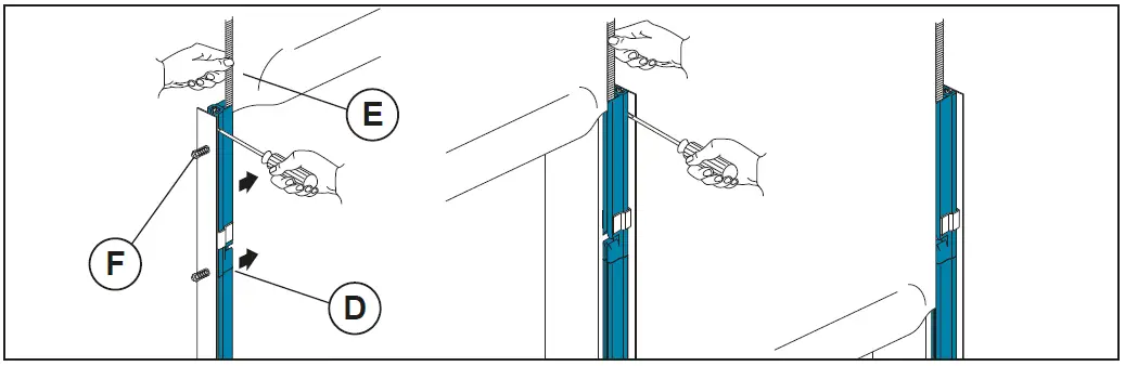
- Close the upper part of the plastic guides (D) by pushing on the outer side.
- Insert each tooth side edge (E) of the curtain in the relevant guide, if necessary to make easier the operation remove the higher screw (F).
- Roll down the curtain so the bottom edge is 0.5m beneath the curtain inlet slot.
USE INSTRUCTIONS
GENERAL SAFETY PRECAUTIONS
This user handbook is an integral and essential part of the product and must be delivered to the users. Keep this document and pass it on to any future users.
This automation is a “vertical-roll door”; it must be used for the specific purpose for which it was designed. Any other use is to be considered inappropriate and so dangerous. Assa Abloy Entrance Systems AB declines all responsibility for damage caused by improper, incorrect or unreasonable use. The device may be used by children over the age of 8 and by people with reduced physical, sensorial or mental abilities, or lack of experience or knowledge, as long as they are properly supervised or have been instructed in the safe use of the device and the relative hazards.
Cleaning and maintenance work must not be carried out by children unless they are supervised.
USE PRECAUTIONS
- Do not enter the door action area while the door is moving.
- In the event of a fault or malfunctioning, turn off the main switch. The operations of maintenance, adjustment and repair must be carried out by skilled and authorised staff.
- Each automation has its own “Installation and Maintenance handbook”, reporting the periodical maintenance plan. Please take care to check all the safety devices.
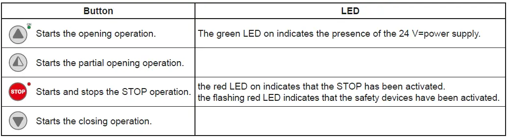
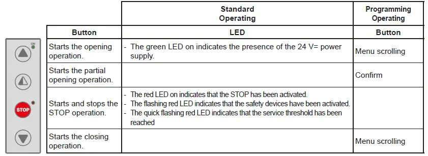
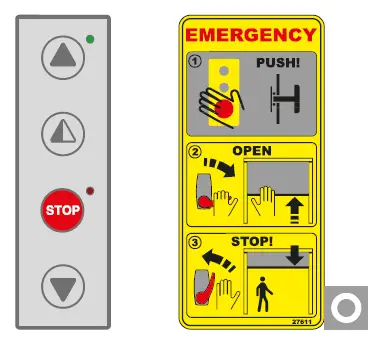
BUTTONS
 Full opening: the door opens completely. The stroke can be fixed via the end stop microswitch.
 Partial opening: the door opens partially, to a point time-regulated by the RP trimmer.
 STOP: the door stops immediately.
 Closing: the door closes completely. The stroke can be fixed via the end stop microswitch.
MANUAL RELEASE LEVER (for emergency reopening).
Warning: before using the manual lever, turn the equipment off, putting the main switch on “0”.
- When the lever is released, the brake is regularly working.
- Pulling the lever, the brake is unclamped.
To raise manually the panel, in case of power lacking or damage, act as follows: - pull the release lever (fig. 2), releasing the brake;
- raise the panel on open door position;
- leave the lever back (fig. 3), in order to run the brake again.
Stop the opening of the panel before the safety edge hits the crosspiece.
| Part | Part number | Cycles / hour | Abusive Environment (1) | ||
| <10 Low Traffic | <30 Medium Traffic | >30 High Traffic | |||
| Months | Months | Months | |||
| Limit switch group (if 400V) | 6K10GF | 36 | 24 | 12 | 12 |
| Limit switch (if 400V) | 5M | 48 | 36 | 24 | 24 |
| Brake disc | 21572 | 36 | 24 | 12 | 12 |
| Brake disc guide | 21571 | 36 | 24 | 12 | 12 |
| Upper guide with lens | 29198ASOL | 48 | 36 | 24 | 24 |
| Upper guide | 281068 | 48 | 36 | 24 | 24 |
| Lower guide | 6BGBSC | 48 | 36 | 24 | 24 |
| Belt counterweight | 6KTFCS | 36 | 24 | 12 | 12 |
| Guide compensation spring | KSPRING | 36 | 24 | 12 | 12 |
| Lens group wide screen | 6GLSLEC | 36 | 24 | 12 | 12 |
(1) Dirty or dusty environment, operating temperature near to 0°C or over 35°C, wind pressure within 20% of maximum limit.
| Date | Counter | Signature |
APPLICATIONS
Use: 5 (minimum 5 years of working life with 600 cycles a day)
Applications: HEAVY DUTY (for industrial and commercial access with heavy duty use).
- Service class, running times, and the number of consecutive cycles are to be taken as merely indicative having been statistically determined under average operating conditions, and cannot therefore be applied to each individual case. Reference is to the period when the product functions without the need for any extraordinary maintenance.
- Independent variables such as friction, balancing and environmental factors may substantially alter the lifespan or performance characteristics of the automatic access or parts thereof (including the automatic systems). It is the responsibility of the installer to adopt suitable safety measures for each single installation.
SOUND PRESSURE
sound pressure level LPa ≤ 70 dBa


