![]() SL710 Water Pressure Sensor
SL710 Water Pressure Sensor
SL710 Water Pressure Sensor User
Manual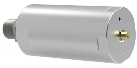
General
SL710 series is a low-power water pressure monitoring sensor. The pressure seat is processed with 17-4PH stainless steel one-piece structure, with high overload performance. The pressure interface has no welds, silicone oil or other organic substances, and has good sealing performance. LoRa wireless communication ensure low power consumption, long distance, built-in high-capacity lithium sub battery and long service life. It can be used in low-power wide area IOT scenarios such as water pipe and valve pressure detection.
| Sensor Type | Model No. |
| Water Pressure Sensor | SL710CN, SL710EU,SL710US,SL710AS |
Note
CN: LoRaWAN CN470,Frequency:470~510 MHz
EU: LoRaWAN EU868,Frequency:863~870 MHz
US: LoRaWAN US915,Frequency:902~928 MHz
AS: LoRaWAN AS923,Frequency:920~925 MHz
1.1.Main Features:
- 1.The maximum transmission power is 22dbm, the transmission distance is long, and the open space can reach 3-5 km.
- 2.Built in 19ah high-capacity lithium sub battery, with a service life of more than 5 years.
- 3.The new generation of pressure transmitter is adopted, which has the electrical characteristics of high precision, high reliability and low power consumption.
- 4.Wireless inquiry and modification of configuration parameters are convenient for on-site installation and maintenance.
- 5.Open communication protocol and access to the third-party Lora gateway with simple configuration.
- 6.Full industrial chip design, working temperature range -40 ℃ ~+85 ℃.
- 7.IP66 waterproof design, suitable for harsh industrial environment.
1.2. Parameters
| Parameters | Feature |
| CPU | STM32L151 CPU |
| Wireless | LoRa(SX1268/SX1262) |
| Encryption | AES128 |
| Power | Built-in Li-battery (Non-rechargeable) |
| Capacity | 19000 mAh |
| Battery life | 8 Years(Data collecting every 5 seconds data uploading every mins @SF9) |
| Measure Range | 0~3.5 MPa |
| Precision | ±0.5 %FS |
| Long Time Stability | ±0.25 %FS |
| Parameters | Feature |
| Respond Time | 5 Seconds(e.g data collecting time, configurable) |
| Communication | Half-duplex |
| Data Speed | 300bps ~ 62.5 kbps |
| Size | 102mm X 60mm X 25mm |
| Working Temperature | -40℃~85℃ |
| TX Power | Max 22dBm |
| Sensitivity | -140 dBm |
| Antenna | SMA |
| Frequency | SX1268: CN470 SX1262: EU868 / US915 / AS923 |
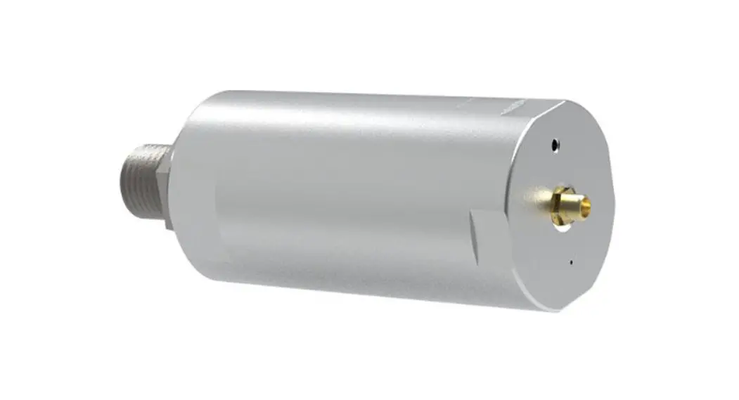
1.3. Product Detail
Front 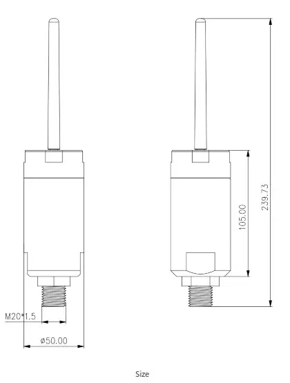
Installation
- Do not forcibly rotate the cylinder part of the sensor to avoid damaging the internal circuit of the sensor
- When installing, please use a wrench to twist the hexagon nut part, and do not force the installation through the cylinder part of the sensor.
- The impulse piping should be as short as possible and avoid sharp bends.
- The installation slope of impulse piping should not be less than 1:12 to avoid sedimentation.
- The layout of the impulse piping shall enable the bubbles in the measured liquid or the sediment in the measured gas to flow back to the process piping.
- During installation, pay attention to the sealing of the interface to avoid oil leakage.
2.1.Magnetic induction trigger
The sensor enters the configuration mode through magnet induction triggering. When there is no magnet close to the magnetic induction area by default, the sensor is in a low-power operation state. When a magnet enters the sensing area, the sensor will trigger a configuration wait mode. (the magnet only needs to be detected once, and it is notnecessary or recommended to stay in the sensing area for a long time.)
After entering the configuration waiting mode, the indicator light will remain green. At this time, LoRa dongle can be used for configuration and query. When there is configuration or query operation, the sensor will automatically extend the configuration time by 30s. If there is no operation for 30 seconds, enter the low-power operation mode.
2.2. Indicator
There is one indicator on the sensor with two colors: red and green.
2.2.1. Configuration indicator
while magnetic induction trigger, and in configuration, the indicator is green. While indicator is off, and sensor is in low power mode.
2.2.2. TX Indicator
While the sensor uploading data, and the indicator flushes in green.
2.2.3. Fault Indicator
While there is something wrong with the sensor, the indicator flushed in red.
When the device enters the configuration mode, it supports wireless at commands and can be configured wirelessly through Rejeee USB dongle.
You can use Sensor Tool for configuration.
Follow steps below:http://doc.rejeee.com/web/#/32?page_id=449
2.5.Antenna
The antenna interface of the equipment adopts standard SMA and the specification of external thread and internal hole. During installation, attention shall be paid to voiding
metal and strong interference equipment. If the installation environment is poor, it is recommended to use a sucker antenna with feeder for installation.
2.6.Data Uploading
When sensor turn on, it will send data immediately.
When the pressure changes more than the set change compared with the last reported data, data uploading immediately.
When the system heartbeat cycle time expires, data uploading.
Configuration
3.1.Data check period
The default check period of the system is 5 seconds, the minimum configurable is 1 second, and the maximum configurable is 65553 seconds. The smaller the period is, the more sensitive the response will be, whereas the power consumption will increase.
3.2.Data uplink period
The default data uplink period of the system is 10 minutes (equivalent to heartbeat transmission). For example, in the environment of constant water pressure, the data is uploading every 10 minutes, and this parameter can be adjusted according to the actual situation.
3.3.Calibration
The system does not configure the calibration value by default (i.e. 0). The user can modify the calibration value as needed. Negative numbers are supported. The unit is PA 3.4.Variation
The system does not configure the change amount by default (that is, 0). In the water pressure sensor equipment, because the equipment range is generally large, when the change amount is 0, 5000 PA is automatically used as the change amount in the equipment for logical judgment.
The purpose of the design variation is to support the equipment to judge the variation according to the sampling cycle while reporting it by cycle. When the sampling data and the last sent data exceed the change amount, they will be reported immediately without waiting for the reporting cycle time. In order to support a rapid response to the measured object.
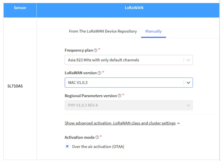
3.5. Connect to LoRaWAN Network
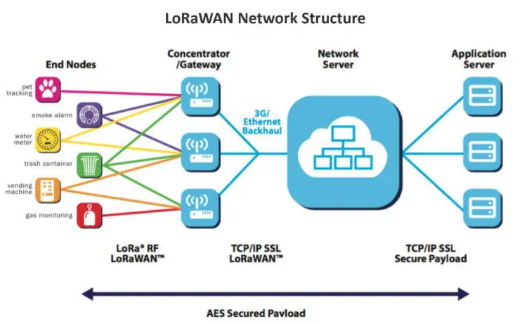
SL710 water pressure sensor is based on standard LoRaWAN Class A/C, so you can connect to any LoRaWAN network through OTAA or ABP.
On the package of device, you can find information as below, with this information, you can connect to any LoRaWAN server.
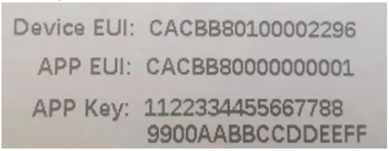
Here below take TTN as an example about how to connect the device to TTN server, please make sure to choose manually and the right frequency plan as below:
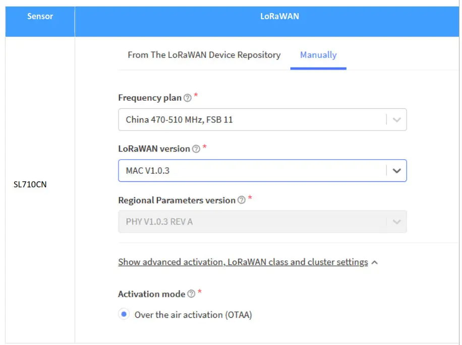
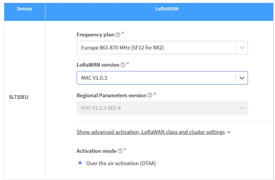
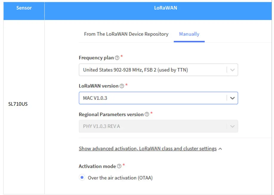
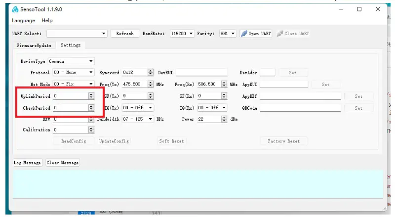
3.5.1 Data Configuration
Normally customer only needs to configure the following information under LoRaWAN:
- Uplink Period: Data uploading Period, that means sensor collect data and send to gateway
- Check Period: Data collecting period, that means sensor collect data but not upload
Wireless Data Format
4.1 SIP(02/03)— LoRaWAN
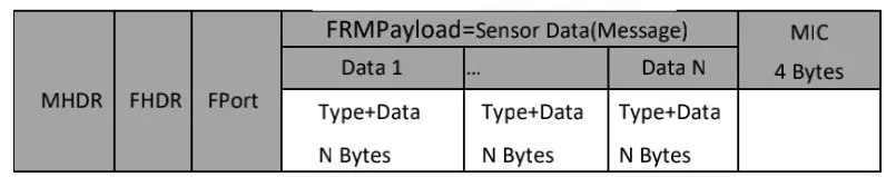
FPort:1
FRM Payload: e.g sensor data(Message Body)
Refer to Renee sensor data。
4.2 Sensor Data
4.2.1 Device Information(0x00)
| Type | Value | Value | Value |
| 1 Byte | 3 bit | 5bit | 1 Byte |
| 0x00 | Version | Battery Level | Reserve |
4.2.3.Pressure(0x07)
| Type 1 Byte | Value 4 Bytes | Note |
| 0x07 | Pressure | 4-byte signed integer, default unit P |
Feature Test
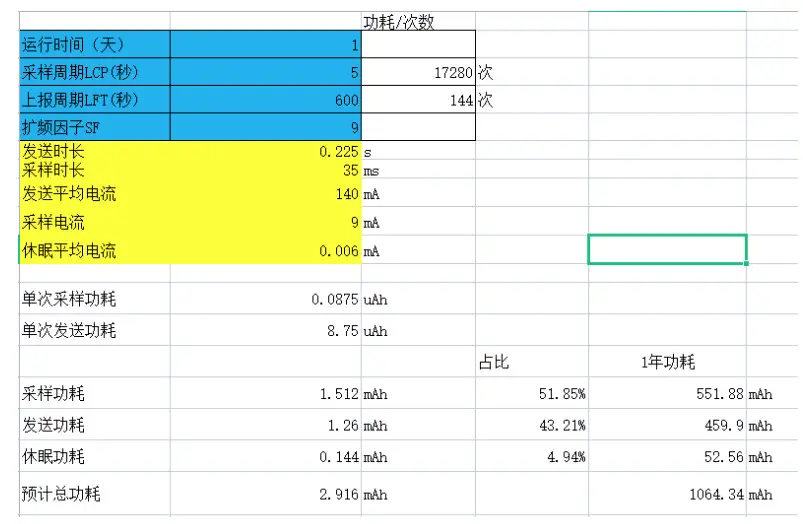
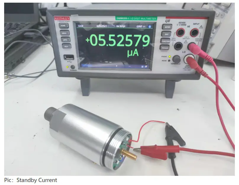
5.1.Standby Current
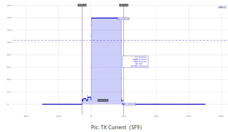
5.2. Sensor TX Current
5.3.Sensitivity Test
| SF | dBm, @BW=125K, 470M 1 It |
| SF=7 | -126 |
| SF=8 | -129 |
| SF=9 | -131 |
| SF=10 | -134 |
| S F=11 | -136 |
| SF=12 | -139 |
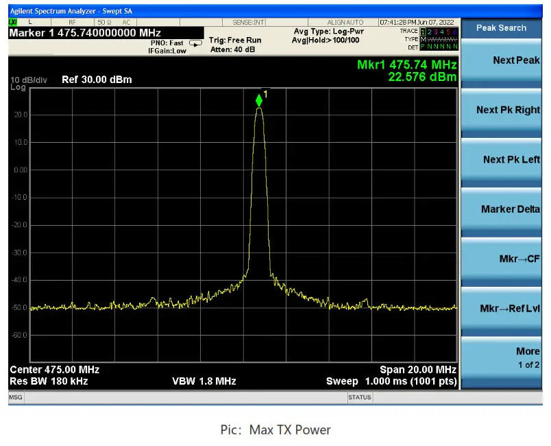
5.4.TX Power Test
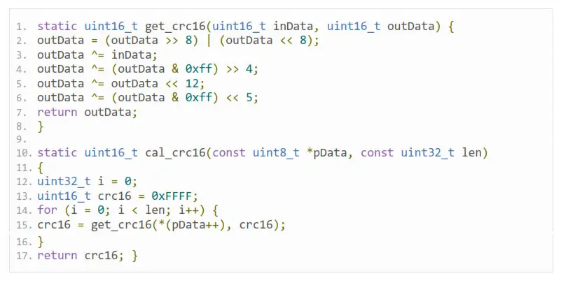
CRC Example
![]()


