![]()
Quick start guide 
NVIP-5VE-4501
SAFEGUARDS AND WARNINGS
THE PRODUCT MEETS THE REQUIREMENTS CONTAINED IN THE FOLLOWING DIRECTIVES: DIRECTIVE 2014/30/EU OF THE EUROPEAN PARLIAMENT AND OF THE COUNCIL of 26 February 2014 on the harmonization of the laws of the Member States relating to electromagnetic compatibility (OJ L 96, 29.3.2014, p. 79–106, with changes)
 DIRECTIVE 2012/19/EU OF THE EUROPEAN PARLIAMENT AND OF THE COUNCIL of 4 July 2012 on waste electrical and electronic equipment (WEEE) (OJ L 197, 24.7.2012, p. 38–71, with changes)
![]() DIRECTIVE 2011/65/EU OF THE EUROPEAN PARLIAMENT AND OF THE COUNCIL of 8 June 2011 on the restriction of the use of certain hazardous substances in electrical and electronic equipment (OJ L 174, 1.7.2011, p. 88–110, with changes)
DIRECTIVE 2011/65/EU OF THE EUROPEAN PARLIAMENT AND OF THE COUNCIL of 8 June 2011 on the restriction of the use of certain hazardous substances in electrical and electronic equipment (OJ L 174, 1.7.2011, p. 88–110, with changes)
Information
The device, as an element of a professional CCTV system used for supervision and control, is not intended for self-installation in households by people without specialist knowledge.
Exclusion of liability in case of damaged data on disks or other devices or media:
The manufacturer is not liable in the event of damage or loss of data contained on disks or other devices or media during the operation of the Product.
Obligation to consult with the Manufacturer before performing an activity not provided for in the operating manual or other documents:
Before performing an action that is not provided for in the Product manual, other documents attached to the Product or does not result from the normal purpose of the Product, please contact the Manufacturer under the pain of excluding the Producer’s liability for the consequences of such an action.![]() Pictures in this publication showing camera views can be simulations. Actual camera images may vary depending on the type, model, settings, observation area, or environmental conditions.
Pictures in this publication showing camera views can be simulations. Actual camera images may vary depending on the type, model, settings, observation area, or environmental conditions.
WARNING!
THE KNOWLEDGE OF THIS MANUAL IS AN NECESSARY CONDITION FOR THE PROPER USE OF THE DEVICE. PLEASE READ IT BEFORE INSTALLING AND OPERATING THE DEVICE.
WARNING!
THE USER IS NOT ALLOWED TO DISASSEMBLE THE CASING AS THERE ARE NO USER-SERVICEABLE PARTS INSIDE THIS UNIT. ONLY AUTHORIZED SERVICE PERSONNEL MAY OPEN THE UNIT
- Prior to undertaking any action please consult the following manual and read all the safety and operating instructions before starting the device.
- Please keep this manual for the lifespan of the device in case referring to the contents of this manual is necessary;
- All the safety precautions referred to in this manual should be strictly followed, as they have a direct influence on the user’s safety and durability, and reliability of the device;
- All actions conducted by the servicemen and users must be accomplished in accordance with the user’s manual;
- The device should be disconnected from power sources during maintenance procedures;
- Usage of additional devices and components neither provided nor recommended by the producer is forbidden;
- Mounting the device in places where proper ventilation cannot be provided (e. g. closed lockers etc.) is not recommended since it may lead to heat build-up and damage the device itself as a consequence;
- Mounting the camera on an unstable surface or using not recommended mounts is forbidden.
The improperly mounted cameras may cause a fatal accident or maybe seriously damage themselves. The camera must be mounted by qualified personnel with proper authorization, in accordance with this user’s manual. - The device should be supplied only from power sources whose parameters are in accordance with those specified by the producer in the camera technical datasheet. Therefore, it is forbidden to supply the camera from a power source with unknown parameters, unstable or not meeting the producer’s requirements;
Due to the product being constantly enhanced and optimized, certain parameters and functions described in the manual in question may change without further notice.
We strongly suggest visiting the www.novuscctv.com/en website in order to access the newest full manual
FOREWORD INFORMATION
TECHNICAL SPECIFICATION
| IMAGE | |
| Image Sensor | 5 MPX CMOS sensor 1/2.7” SmartSens |
| Number of Effective Pixels | 2880 (H) x 1620 (V) |
| Min. Illumination | 0.03 lx/F1.2 – color mode, 0 lx (IR on) – B/W mode |
| Electronic Shutter | auto/manual: 1/5 s ~ 1/20000 s |
| Digital Slow Shutter (DSS) | up to 1/5 s |
| Wide Dynamic Range (WDR) | yes (double scan sensor), 120dB |
| Digital Noise Reduction (DNR) | 2D, 3D |
| Defog Function (F-DNR) | yes |
| Highlight Compensation (HLC) | yes |
| Back Light Compensation (BLC) | yes |
| Reduction of image flicker (Antiflicker) | yes |
| LENS | |
| Lens Type | fixed focal, f=2.8 mm/F1.6 |
| DAY/NIGHT | |
| Switching Type | mechanical IR cut filter |
| Switching Mode | auto, manual, time |
| Switching Delay | 1 ~ 36 s |
| Switching Schedule | yes |
| Visible Light Sensor | yes |
| NETWORK | |
| Stream Resolution | 2880 x 1620, 2560 x 1440 (QHD), 2304 x 1296, 1920 x 1080 (Full HD), 1280 x 720 (HD), 640 x 480 (VGA), 320 x 240 (QVGA) |
| Frame Rate | 30 fps for each resolution |
| Multistreaming Mode | 3 streams |
| Video/Audio Compression | H.264, H.264+, H.265, H.265+/G.711 |
| Number of Simultaneous Connections | max. 10 |
| Bandwidth | 60 Mb/s in total |
| Network Protocols Support | HTTP, TCP/IP, IPv4, HTTPS, FTP, DHCP, DNS, DDNS, NTP, RTSP, RTP, UPnP, SNMP, SMTP, P2P, HTML5 |
| ONVIF Protocol Support | Profile S/G |
| Camera Configuration | from Internet Explorer browser languages: Polish, English, Russian, and others |
| Compatible Software | NMS |
| Mobile applications | RxCamView (iPhone, Android) |
| OTHER FUNCTIONS | |
| Privacy Zones | 4 video mask type: single color |
| Motion Detection | yes |
| Audio Detection | yes |
| Video Content Analysis (VCA) | abandoned object, object disappearance, line cross, zone entrance, zone exit, multi loiter, cross counting, heat map, queue length detection, objects distinguishing |
| Image Processing | 180˚image rotation, vertical flip, horizontal flip |
| Pre-alarm/Postalarm | up to 5 s/up to 30 s |
| System Reaction to Alarm Events | an e-mail with an attachment, saving the file on FTP server, saving the file on SD card, saving in the cloud storage |
| Restoring default settings | via web browser, using the reset button |
| IR LED | |
| LED Number | 2 |
| Range | 30 m |
| Smart IR | yes (hardware support) |
| INTERFACES | |
| Audio Input/Output | built-in microphone |
| Network Interface | 1 x Ethernet – RJ-45 interface, 10/100 Mbit/s |
| Memory Card Slot | microSD – capacity up to 256GB |
| INSTALLATION PARAMETERS | |
| Dimensions (mm) | 100 (Ф) x 90 (H) |
| Weight | 0.43 kg |
| Degree of Protection | IP 66 (details in the user’s manual on page 7) |
| Enclosure | vandalproof aluminium, white |
| Power Supply | PoE, 12 VDC |
| Surge protection | TVS 4000 V |
| Power Consumption | 2 W, 4 W (IR on) |
| Operating Temperature | -30°C ~ 55°C |
| Humidity | max. 95%, relative (non-condensing) |
1.1. Camera dimensions (in millimeters) 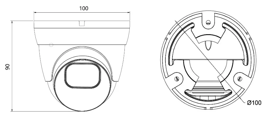
START-UP AND INITIAL CONFIGURATION
Caution:
If the device was brought from a room with a lower temperature, wait until it reaches the temperature of the room in which it is to work. Do not switch the device immediately after bringing it from a cooler place. The condensation of water vapor can cause short circuits and consequently damage the device.
START-UP AND INITIAL CONFIGURATION
Before starting the device familiarize yourself with the description and the role of particular inputs, outputs, and adjusting elements that the device is equipped with.
2.1. Description of the camera’s electrical connectors 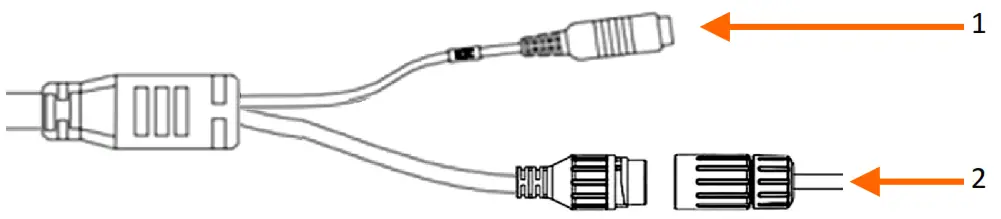
- 12VDC camera power socket
- 100 Mb/s Ethernet port (hermetic RJ-45 socket)
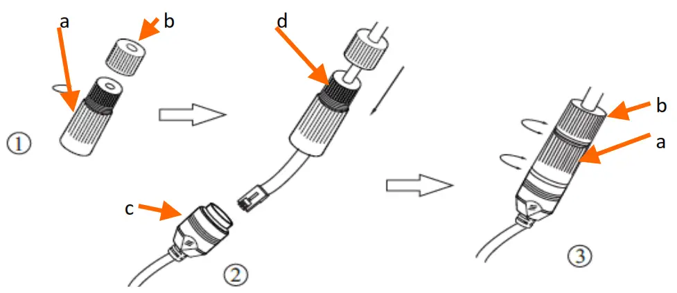
2.2. Connecting ethernet cable
To maintain hermeticity network cable connection, follow the instructions below:
- Unscrew the nut (b) from the connector cover (a), mount the sealing ring on the socket (c)
- Route the network cable through the components (a) and (b). Plug the RJ-45 connector into the socket (c)
- Screw the connector cover (a) on the socket (c). Inside the upper part of the connector cover (a) push into the stop the seal of the cable (d) – the seal is cut to insert on the network cable.
- Tighten up to the stop nut (b)
Caution:
The 12VDC power connector is not hermetic. The user should seal them on his own.
2.3. “Two-way power” function
The camera is equipped with the “Two-way power” function. When the camera is connected to the PoE switch, 12VDC is available in the 12V camera power socket. This allows the user to power the receiver with low power consumption, e.g. a microphone, from the camera power socket.
![]() The maximum power consumption of the device using the “Two-way power” function is 3W.
The maximum power consumption of the device using the “Two-way power” function is 3W.
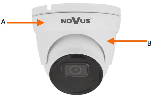
2.4. Camera mounting
To mount a camera please follow the instructions below:
- Remove the retaining ring (A) by turning it counter-clockwise
- Remove the camera cover (B), remove the camera from the base
- Put the bracket to the wall in a desired mounting place (with a cable hole). Taking the bracket’s base screw holes as a pattern, mark future drilling holes for screws.
- Drill holes in accordance with previously done markings and base hole placement.
- Mount the camera base using the supplied plugs and screws.
- Connect the camera cables, put the camera on the base, attach the cover (B) and pre-tighten the retaining ring (A)
- Adjust camera position.
- Tighten to the stop retaining ring (A)
Caution:
Please note that the wall or ceiling must have enough strength to support the camera.
Caution:
The declared degree of protection of the camera relates to its housing and does not take into account the possibility of moisture infiltration into the interior of the camera by connecting cables. Connection cables protection i.e. sealing up is the responsibility of the camera installer. The manufacturer is not liable for any damages to the camera caused as a result of failing in performing that activity by the installer, which also means that camera damaged in that way is not subject to warranty repairs.
2.5. Starting the camera
To start the camera, connect the Ethernet cable to the RJ45 network socket of the IP camera, and the other end to the network switch. As a power source, it is possible to use an externally stabilized power supply with parameters that meet the requirements of the camera or PoE network switch.
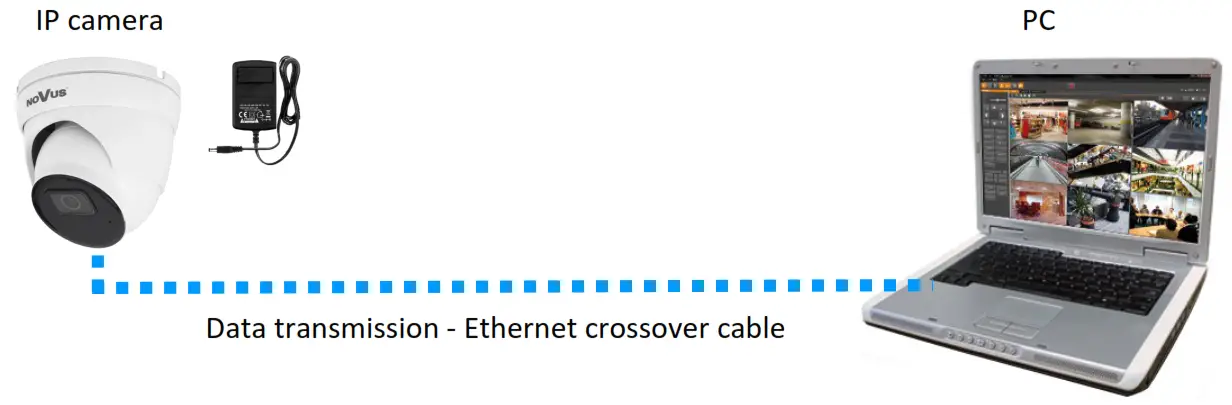
The recommended method of starting and configuring the IP camera is to connect it to a PC or laptop in a dedicated network switch to which no other devices are connected. In the case of a power supply from an external power supply, it is enough to use any network switch or a cable connected directly to the computer. For network configuration data (IP address, gateway, netmask, etc.), please contact the administrator of the network in which the device is to work.
• Connection using network switch with PoE support 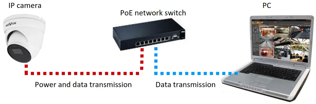
• Connection using the external power supply and network switch
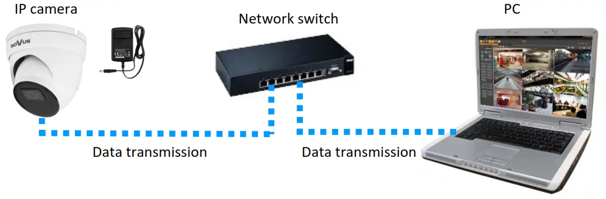 • Connection using the camera’s external power supply and an Ethernet crossover cable
2.6. Parameter configuration using a web browser
The default network settings for the camera are:
- IP address= 192.168.1.200
- Network mask – 255.255.255.0
- Gateway – 192.168.1.1
- User name – root
- Password – pass
Knowing the camera’s IP address you need to appropriately set the PC IP address, so the two devices can operate in one network subnet ( e.g. for IP 192.168.1.1, the appropriate address for the camera ranges from 192.168.1.2 to 192.168.1.254, for example, 192.168.1.60). It is not allowed to set the same addresses for the camera and PC computer
You can either set a network configuration (IP address, gateway, netmask, etc.) of the NOVUS IP camera yourself or select DHCP mode (DHCP server is required in this method in the target network) by using a web browser or by NMS software. When you use the DHCP server checks the IP address lease and its linking with the camera MAC address to avoid changing or losing the IP address during device operation or network/ DHCP server breakdown. You have to remember to use a new camera IP address after changing network parameters.
After the network setting configuration has been done, the camera can be connected to a target network.
2.7. Security recommendations for network architecture and configuration
WARNING!
Below are shown security recommendations for network architecture and configuration of CCTV systems that are connected to the Internet to reduce the risk of unauthorized interference with the system by a third party.
- Absolutely change the default passwords and user names (if the device gives this possibility) of all applied network devices (recorders, cameras, routers, network switches, etc.) to the severe complexity password. Use lowercase and uppercase letters, numbers, and special characters if there is such a possibility.
- Depending on the available functionality in the order to restrict access to the user network devices at
the administrator account level, it is recommended to configure the user’s accounts accordingly. - Do not use the DMZ function (Demilitarized zone) in your router. Using that function you open access to the recorder system from the Internet on all ports, which gives the possibility for unauthorized interference with the system.
Instead of DMZ use port forwarding to redirect only the ports which are necessary for the performance of the connection (detailed information about ports of communication in different models of recorders, cameras, etc. can be found in the operating instructions). - Use routers with firewall function and make sure it is enabled and properly configured.
- It is recommended to change the default network communication port numbers of used devices if there is such a possibility.
- If used network devices have a UPnP feature and it is not used, turn it off.
- If used network devices have a P2P feature and it is not used, turn it off.
- If used network devices support HTTPS protocol for connection, it is recommended to use it.
- If used network devices support IP filtering for authorized connections function, it is recommended to use it.
- If the used recorder has two network interfaces it is recommended to use both of them to physically separate the network for cameras and the network for Internet connection. The only device in the system, accessible from the Internet will be a recorder – there will be no physical access directly to any camera.
NETWORK CONNECTION USING WEB BROWSER
3.1. Recommended PC specification for web browser connections
The following requirements apply to the connection with the IP camera assuming smooth video display at the maximum resolution.
- CPU Intel Core i3 3GHz or newer
- RAM Memory min. 8 GB
- Graphic card (any Nvidia GeForce 512MB Ram or equivalent)
- OS Windows 8/8.1/10
- The network card 100/1000 Mb/s
3.2. First connection to the camera via a web browser
Enter the IP address of the camera in the address bar of the web browser. After connection, the following will be displayed: the administrator password definition window and then the security question window, allowing you to regain access to the camera in the event of forgetting the administrator password, without the need to reset.
Defining the administrator password
When connecting to the camera for the first time, the administrator password definition window is displayed.
![]() When connecting to the camera for the first time, the password definition stage windows may appear in English.
When connecting to the camera for the first time, the password definition stage windows may appear in English.
Enter the password for the administrator account in the “New Password” field, and then repeat for confirmation in the “Confirm Password” field. The strength of the password is indicated on the “Password Strength” indicator and the requirements for its creation can be seen in the pop-up window that shows up by hovering over the question mark symbol.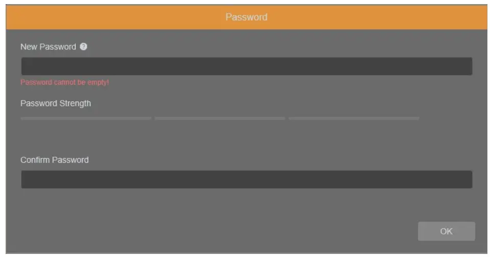
After defining the administrator password, the password recovery question selection window is displayed.
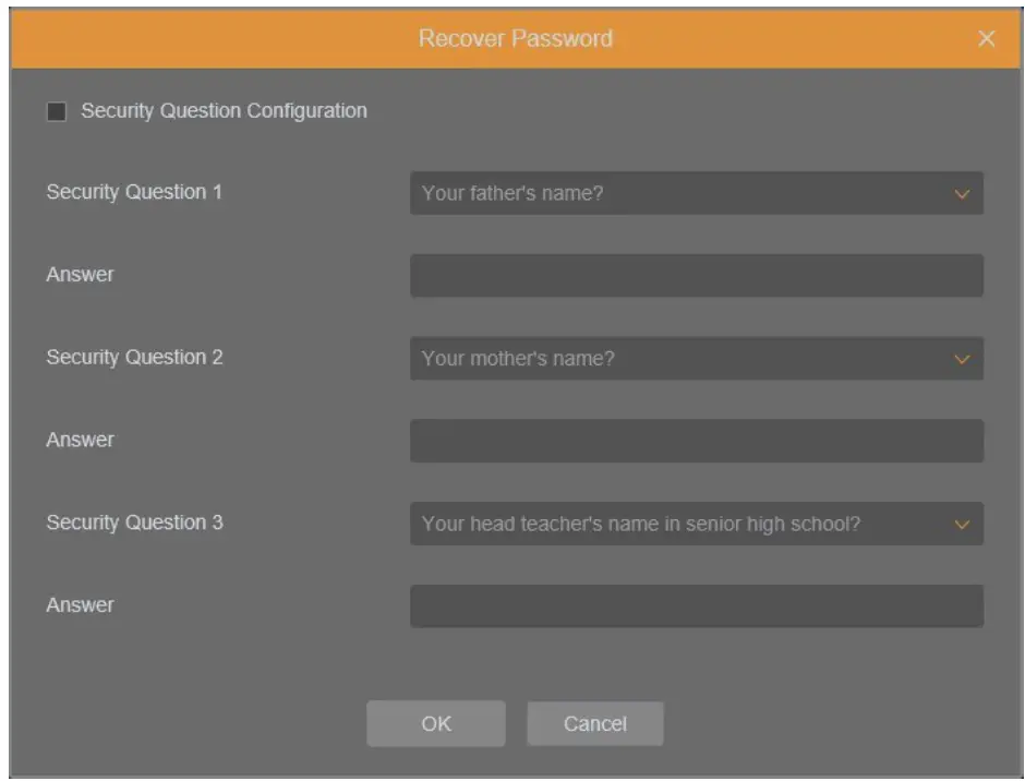
To activate the security questions, select the “Security Question Configuration” option. Then select the questions from the “Security Question” lists and enter your own answers in the “Answer” fields.
![]() It is obligatory to answer all the questions. Selected questions and answers should be stored in a place protected against unauthorized access. After saving the answers, they cannot be changed, and giving new ones is possible after restoring the factory settings.
It is obligatory to answer all the questions. Selected questions and answers should be stored in a place protected against unauthorized access. After saving the answers, they cannot be changed, and giving new ones is possible after restoring the factory settings.
Since the camera does not analyze the sense of the answer, but only remembers it, it can be any string of characters. The same answer can be given to each of the questions.
After making the necessary changes, save them by pressing the “OK” button. The camera confirms the correctness of the operations by displaying a confirmation window. After pressing the “OK” button in the confirmation window, the login window to the web panel of the camera is displayed.
![]() It is not mandatory to activate security questions. This step can be skipped by pressing the “OK” button without selecting “Security Question Configuration”, or by pressing the “Cancel” button. However, in this case, the password recovery option is not available and the only way to restore access to the camera in case the password is lost is to use the button reset.
It is not mandatory to activate security questions. This step can be skipped by pressing the “OK” button without selecting “Security Question Configuration”, or by pressing the “Cancel” button. However, in this case, the password recovery option is not available and the only way to restore access to the camera in case the password is lost is to use the button reset.
Administrator password recovery
To regain access to the camera if you forget the password, click on the “Recover password” link in the lower right corner of the login window. The password recovery window is displayed, in which the user must enter the answers provided during the configuration of the answer in the appropriate fields, and then set a new password.
Login to the camera
To log in to the camera, enter the administrator account name and password in the login window. 
After logging in using the Internet Explorer browser, the camera can display a message about the need to install the “SurveillancePluginV2.exe” plug-in, necessary to display video (this message appears if the system was not previously installed the plug-in or if the plug-in is present, but it is in the wrong version).
In this case, click on the “Download and install plug-in” link and follow the installer’s instructions.
After the installation is complete, refresh the browser window. After these steps, the camera image should appear in the live view window.
If the plug-in installation process is interrupted by Windows Security, allow the plug-in to install and run.
Live video can be played only after the player plug-in is installed. Download and install the player. if you have installed the player, restart your browser. (Allow the player in your browser.)
When logging in with a browser using HTML5 (such as Firefox, Chrome, Opera, or Safari), there is no need to install any plug-ins and after entering the username and password, the preview window displays a live image.
USING AND CONFIGURING
4.1. The Remote Preview Interface![]() The following is a view of the live view window in Internet Explorer with the “SurveillancePluginV2.exe” plugin installed. When connecting to the camera from browsers that use HTML5, some menu items and/or options may not be available. This is not a fault, but due to the specific nature of HTML5.
The following is a view of the live view window in Internet Explorer with the “SurveillancePluginV2.exe” plugin installed. When connecting to the camera from browsers that use HTML5, some menu items and/or options may not be available. This is not a fault, but due to the specific nature of HTML5.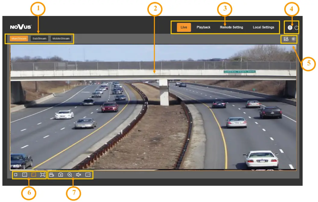
- Select a stream to display in the remote view window.
- Live Preview window.
Double-clicking the left mouse button on the preview window enables and disables the display of the image on the full screen. - Buttons for selecting the operating mode and configuring the camera:
Playback – enables the playback panel of recordings from the memory card
Live – enables preview live stream
Remote Setting – displays the configuration panel camera
Local Setting – displays the configuration panel of paths to snapshot folders - Icon to access the camera:

– displays information about the logged-in user and the version of the applet – logout from the camera - Displays additional information and adjustment panels.

– enables and disables the video analytics event alarm display panel – enables the image adjustment panel. - Picture control buttons:

– enables and disables the live preview – sets the original aspect ratio – fits the image to the browser window – sets fullscreen - Buttons controlling additional functions:

– enables and disables the recording of the video stream to the user’s PC – takes a screenshot and saves it to the user’s PC – enables and disables enlarging the picture – turns audio on and off – enables and disables the pixel counter (displays the size of the selected area)

RESTORING FACTORY SETTINGS
The camera menu has an option to reset the settings to the factory values. To restore the camera settings to the default values, go to the “Load Default” tab (Remote Settings -> Maintain -> Load Default).
Then select the camera options that you want to reset and press the “Save” button. After confirming the administrator password, the camera settings will be restored.
Restoring the factory settings is also possible by pressing and holding for about 5 seconds the reset button, which is located under the lid in the camera housing.
INSTALLING A MEMORY CARD
The microSD memory card slot is located under the lid in the camera housing. 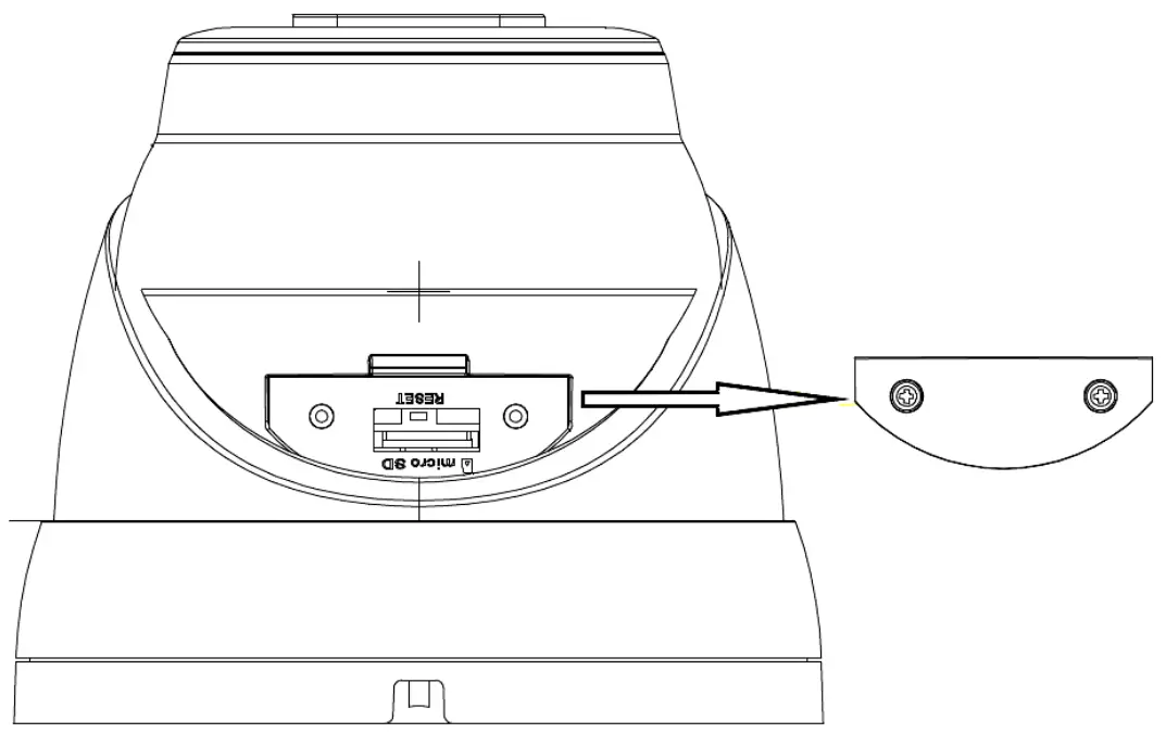
To install a memory card, disconnect the camera’s power supply, remove the screws that secure the lid and insert the card into its slot. After closing the lid and starting the camera, go to the “Remote Setting > HDD” menu and format the memory card.
NOTES![]()
AAT SYSTEMY BEZPIECZEŃSTWA Sp. z o.o.
431 Pulawska St., 02-801 Warsaw, Poland
tel.: +4822 546 0 546, [email protected]
www.novuscctv.com
References
 NOVUS Professional solution for your security systems | Video surveillance (CCTV), Access control
-
NOVUS Professional solution for your security systems | Video surveillance (CCTV), Access control
-
NOVUS Profesjonalne rozwiązanie dla systemów zabezpieczeń | Telewizja przemysłowa CCTV, Kontrola dostępu


