![]()
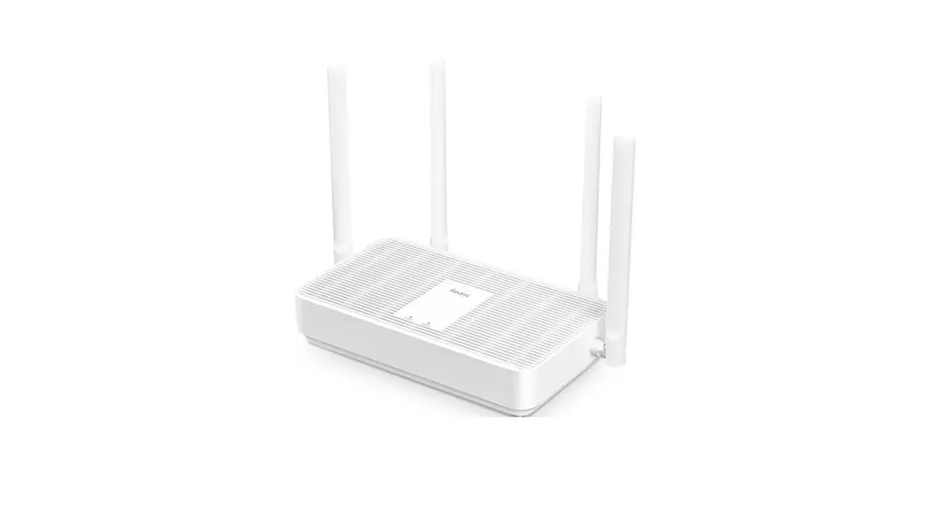
Wi-Fi 6 Router
QUICK Installation Guide
Version: v1.0
Preface
This QIG provides hardware specifications, installation requirements, and how to use your new IEEE802.11ax router/access point.
This QIG is intended for users that understand: Network planning and IP protocols; Field technical support and maintenance Network administration or handle network configuration and maintenance
Due to reasons such as different models, different configurations, and firmware upgrades, there may be differences between contents in this QIG and devices received. Please refer to the actual information shown on the device.
Port number shown in this QIG is for demonstration only, the port number is subject to the actual device.
Table of Contents
- Device Introduction
- Installation Preparation
1. Safety Precautions
2. Environmental Requirement
3. Temperature and Humidity Requirement
4. Accessories
5. Installation Tools - AP Installation
1. Installation Procedure
2. Check Before Installation
3. AP Installation
4. Connect AP To Power Supply
5. Connect AP to network - Appendix
Device
- Device Introduction
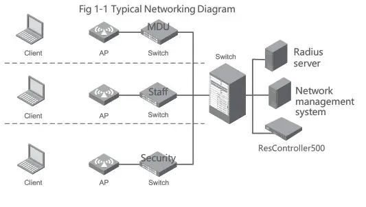
Router/AP working in FIT mode is used together with ResController, all configurations are done from the ResController. A typical networking diagram is shown in Fig 1-1 below.
- Installation Preparation
1. Safety precautions
Only professionals are allowed to install and assemble the AP and its accessories. Please read the safety precautions listed below before installing and operating to avoid environmental pollution and personal ijury.
This note cannot cover all possible risks
- Please take necessary safety measures to ensure the personal safety of installation personnel and protect the Router/AP device from damage.
- Please ensure the ground of the installation site is flat and dry and take necessary anti-skid measures.
- Please ensure that the device to be installed is clean and free of dust.
- Please do not put the device in a wet place and ensure that the installation position of the device will not be exposed to any sources of liquid.
- Please do not put the device and installation tools in the walking area.
Environmental Requirement
Before preparing for installation, the installation conditions shall also be checked to ensure that the device is in a good operating environment for the long term.
Temperature and Humidity Requirement
The temperature and humidity environment requirements for device operation are as follows:
| ITEM | VALUE RANGE |
| Working Temperature | 0°C–40°C |
| Storage Temperature | -40°C^70°C |
| Working Humidity | 570–95% (Non condensing) |
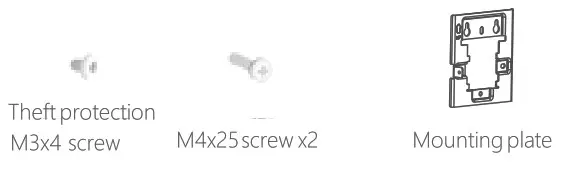
Accessories
Accessories attached to the device as below:

Installation tools (not included)

AP Installation
- Installation Procedure

- Check Before Installation Check below before Router/installation: Please power on the Router/AP, connect Router/AP to Ethernet, check LED indicator status, make sure The Router/works normally. For LED indicator status pls refer to the Appendix Please record the Router/AP MAC address and SN for future support use.
- Router/AP Installation (1) Install the mounting plate into the wall socket by using an M4 screw, see Fig 3-1 (2)Connect the cable to WAN/POE and Pass-Through port on the bottom side of AP
 Note: The Pass-Through ports on the side and bottom of the AP are standard RJ4S ports, which can use as telephone lines or connect according to the actual needs of users.
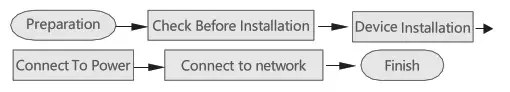
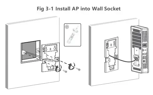
Fig 3-2 Install AP to the Wall
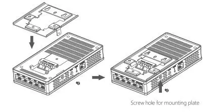
Installation Steps
- first. install the mounting plate onto the Router/AP using the included screw
Screw hole for mounting plate
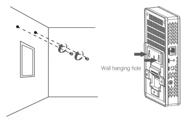
- Punch holes in the wall and install screws

Align the mounting hole on the bottom of the Router/with the lower edge of the protrusion of the mounting plate. Install the protrusion on the mounting plate into the mounting hole of AP, then press it to fix the Router/AP into position. Finally, tighten the theft protection M3x4 screw on side of the Router/AP. See figure below
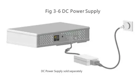
Connect Router/AP to the Power Supply (not included)
The Router/AP supports a DC (not included) and 80L3af/at PoE power supply. Users can choose a suitable power supply type according to the actual networking environment
- Check Before Powering On
After installation, the below points need to be checked before power on the device:
When using a DC power supply, make sure local AC power has a good ground connection
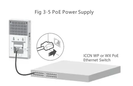
When using PoE power supply, make sure PoE PSE has a good ground connection - PoE Power Supply
Connect PoE port of PoE switches to PoE In port on the bottom of Router/AP with LAN cable to provide Pa power supply to Router/AP. See Fig 3-S below:
- DC Power SupplyNote:
A DC power adaptor is not included in the package.Table 3-1 DC power adaptor specificationITEM SPECIFICATION Power Input 100-240VAC Power Output +12v  1A DC
1A DC
- Power On Check
After connecting the Router/AP to a power source, please check if the LED indicator is normal. For LED indicator status, please refer to Appendix Fig A-3.
Connecting the Router/AP to the network
There is no need to configure AP itself, all configurations are done from ResController if deployed.
Appendix
A.1 Basic Specification
Table A-1 Basic Specification
| ITEM | WIRELESS AP |
| Protocols | IEEE802.11a/b/g/n/ac/ax |
| Dimensions (WxDxH ) | 160mm x 86mm x 30mm |
| Net Weight | 0.25kg / 0.5Ibs |
| Antennas | Intenal anternnas |
| Power Consumption | ≤12.95W(without US8) ≤15.46W(with USB) |
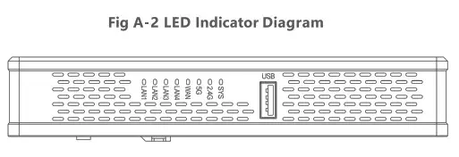
A.2 LED Indicator Notes: LED indicator normal status and corresponding twinkle frequency.
- Blink frequency 0.5Hz: Blink once each second
- Blink frequency 1Hz: Blink once each second
- Blink frequency 2Hz: Blink twice each second
 SYS indicator
- 2.4G & SG WiFi indicator
- WAN/LAN indicator
 SYS indicator
Fig A-3 Indicator Definition
| Indicator | Color | Status | Definition |
| POWER | Red | OFF ON | Power is off or LED indicator is in off status Device is initializing or abnormal initialization |
| WiFi | — | OFF | No wireless client communicating with AP or LED indicator is disabled in firmware |
| Green | Blink | A wireless client is communicating on 2.4G port | |
| Green | Blink | A wireless client is communicating on 5G port | |
| WAN/LAN | — | OFF | No connection on WAN/LAN port |
| Green | ON | Port negotiation rate is 1000Mbps | |
| Blink | Port is working normally at 1000Mbps |
A.3 Ports
1* Console port
4* 10/100/1000M LAN ports
1* 10/100/1000M WAN port with PoE support
1* DC IN (DC power supply not included)
2* Pass-Through ports
1* USB port
1* RESET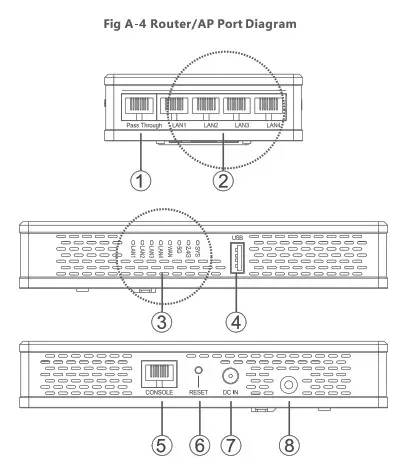
- Pass-Through
- 0 10/100/1000M
- LAN LED Indicator
- USB
- CONSOLE
- ST
- 12V/DC
- Theft protection jack
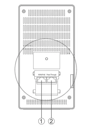
- WAN/PoE In port
- Pass-Through port
Fig A-5 Port Definition
| PORT | STANDARDS | DESCRIPTION |
| Console | RS/EIA-232 | AP management and configuration Note: For maintenance staff use only |
| Ethernet | IEEE802.3 IEEE802.3u | 10/100/1000M Ethernet ports Corresponding ports: GE1/0/2—GE1/0/5 port in MAP file gigabit Ethernet 2— gigabit Ethernet 5 in AC configuration |
| 12V DC | _ | DC Power Input to AP |
| Pass-Through | IEEE802.3 IEEE802.3u | Two Passthrough ports for phone or RJ45 cable connection |
| USB | USB2.0 | Data transmission or power supply |
| Reset | — | Press less 5 seconds, restart AP Press over 5 seconds, restore factory default |
ICC Networking
www.iccnetworking.com
[email protected]
02021 ICC Networking. MI rights reserved


