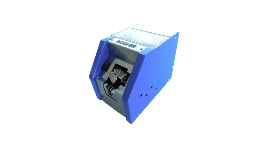
![]() NFK N30 Automatic Screw Feeder
NFK N30 Automatic Screw Feeder
Instruction Manual
AUTOMATIC SCREW FEEDER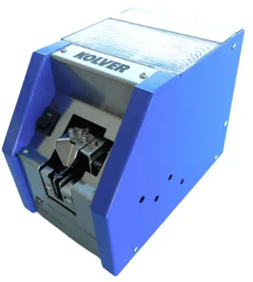
Features
Adjustable for a wide range.
This automatic screw feeder can handle wide range of screws, e.g. metric or self-tapping screws, between M1 and M5 and 20 mm max length.
Working smoothly
The NFK can work continuously without interruptions or jams thanks to the particular loading circuit and to the movement of the brush. Any screw in the wrong position falls in the screw storage so the loading cycle can restart.
Adjustable speed
It’s possible to adjust the vibration speed and the speed of the brush / loading wheel.
Different combinations of speed allow to adapt the NFK to different works.
General instructions
Before performing any such task, please read carefully these instructions and save them for future reference.
NFK Accessories.
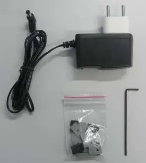
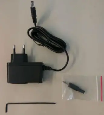
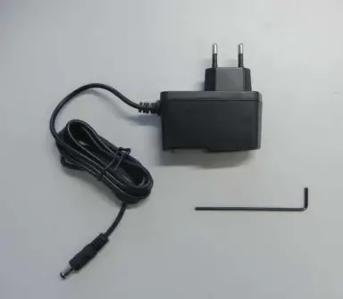
The NFK package contains:
- 1 x NFK already adjusted at the size required
- 1 x Instruction manual
- 1 x AC/DC adapter + power cord
- 1 x kit of spacers
- 1 x hexagonal key

General precautions.
Install the NFK in a stable horizontal position: an inclined base can affect the correct output of the screws. Improper installation could cause the NKF to fall or jam.
Workplace.
Do not operate in presence of oil smoke, steam, moisture or dusts. It may occur fire or electric shock.
Cleaning.
Keep clean the lubricated parts and check them periodically.
Keep the screw storage clean and be careful of possible foreign material inside. Regularly inspect the rail.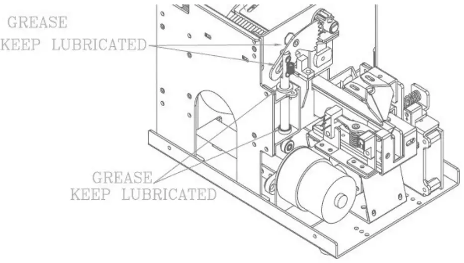
AC/DC Adapter.
Do not use any AC/DC adapter other than the specific one. It may occur fire or electric shock.
Rail.
Handle the rail carefully. It does not need to be lubricated but cleaned periodically. The dirt can block the screw flowing.
Picking up the screws.
Do not exert any force to pick up the screw. Excessive force could break or hit the unit.
Screw.
Do not use dirty or greasy screws, all dirt can clog the NFK. Use only suitable screws (see Technical Data). Do not overfill the storage, the correct amount is described here below. Covers.
Before any performance, make sure that all the covers are closed and secure.
IMPORTANT: Switch off the NFK before opening the covers.
When the NFK is off.
Disconnect the AC/DC adapter, when the unit is not used for an extended period of time.
WARNING. When an abnormality occurs, stop immediately, turn off the power and unplug the power cord of the unit. Contact your Kolver dealer immediately.
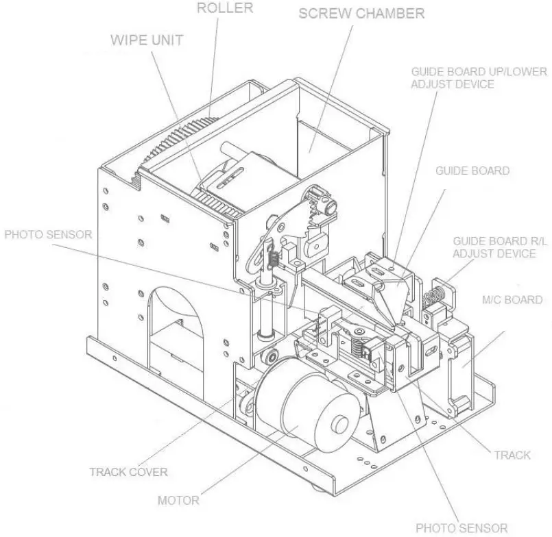
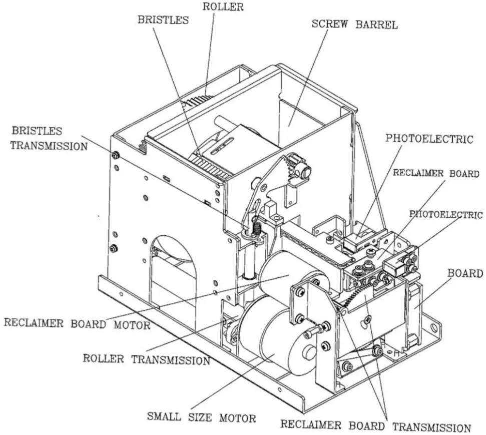
Mechanical description
Technical data
Screw: Suitable for every head shape
D: Head diameter
A: Shank length
L: Total lenght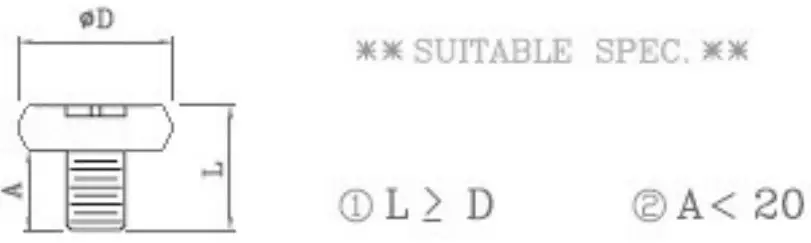 Voltage: 12V DC 500mA
Tension: IN 100/240 AC
OUT 12V DC 1,25A
Dimensions: 184 x 123 x 148 mm (L*W*H)
Weight: 2,75 Kg
Storage temperature: from 0°C to +50°C
IMPORTANT: the item is not grounded!
In case it’s necessary, please connect an eyelet to a screw on the bottom.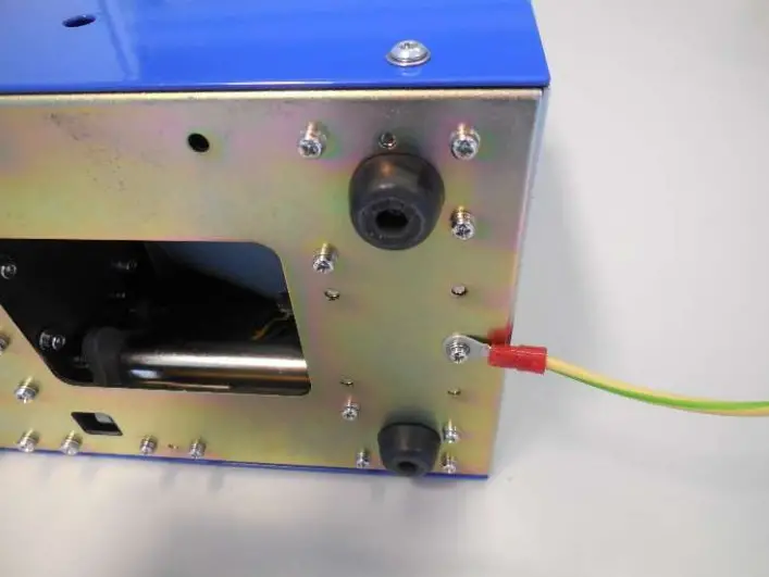
Adjustments
Brush adjustment.
The eject brush places the screws that flows along the track and throws the ones in the wrong position in the storage.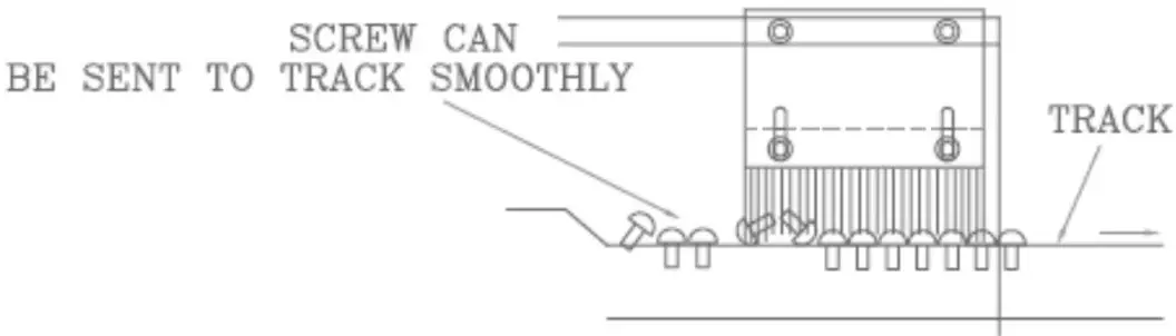
Procedure:
To adjust the eject brush height, loosen the screws in the picture below, raise or lower the brush to the height of the head of your screw.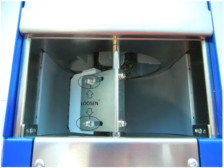 If the brush has been set too high, screws in the wrong position could pass and stop the passage. If too low, the brush could get stuck.
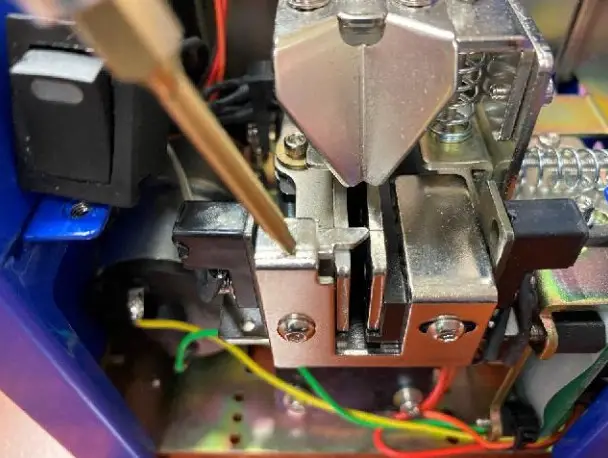
Bit guide & track cover adjustment.
To pick the screw up correctly, the bit guide should be centered on the screw head (see picture below). It’s also possible to adjust it right/left and forward/backward. It should be also adjusted the height of the track cover in such a way as to pass only the screws in the correct position.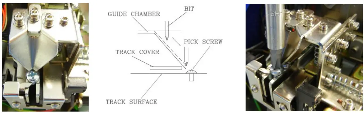 Procedure:
Remove the front panel by unscrewing the 4 screws as in the picture below and by slipping off the power button.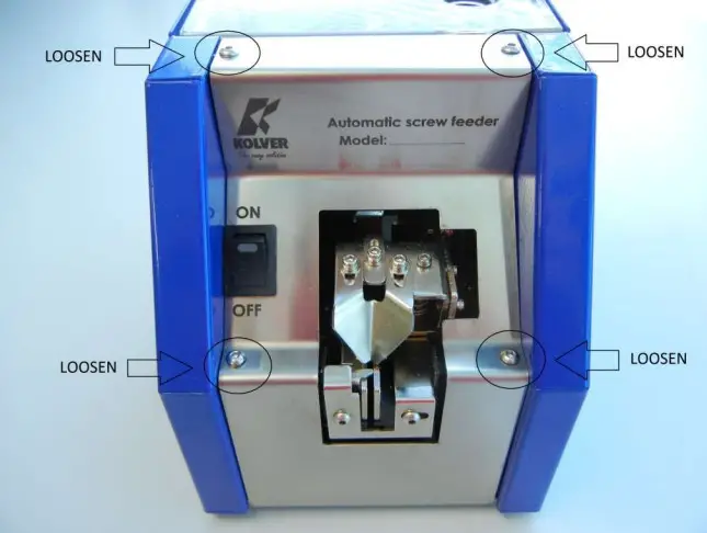
To adjust the bit guide right/left, loosen A screws and turn E screw: clockwise to move the bit guide to the right, and counterclockwise to move it to the left. Once you have found the right spot, tighten A screws.
To move it forward/backward, loosen D screws, find the correct position and fasten it again.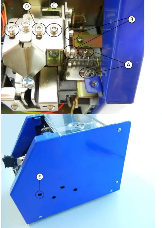 To adjust the height of the block track coverbit guide, loosen B and C screws and turn the screw clockwise to lower, and counterclockwise to raise it. Once you have found the right spot tighten B screws.
To adjust the advancement of the track cover using F screws to cover up to the penultimate screw (see picture here below).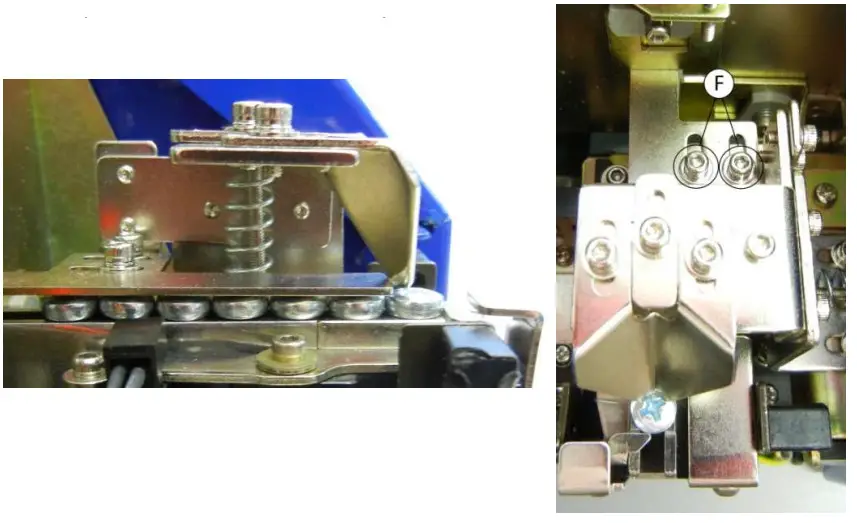 Speed adjustment.
To adjust the vibration speed and the speed of movement of the brush/ loading wheel depends on the use and on the type of screw.
G trimmer adjusts the vibration speed, while H trimmer adjusts simultaneously the speed of the brush and of the wheel of charge. For both the trimmer, if turned clockwise, the speed increases, anticlockwise it decreases.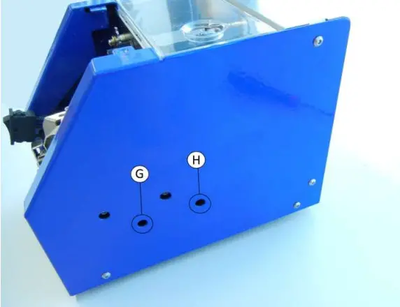 After the adjustments, reassemble the NFK. Make sure that all screws are tightened properly.
Track adjustment.
Thanks to the kit of spacers (from 1.3 to 5.3 mm of thickness ) supplied with the NFK, it is possible to adjust the NFK screws from M1 to M5.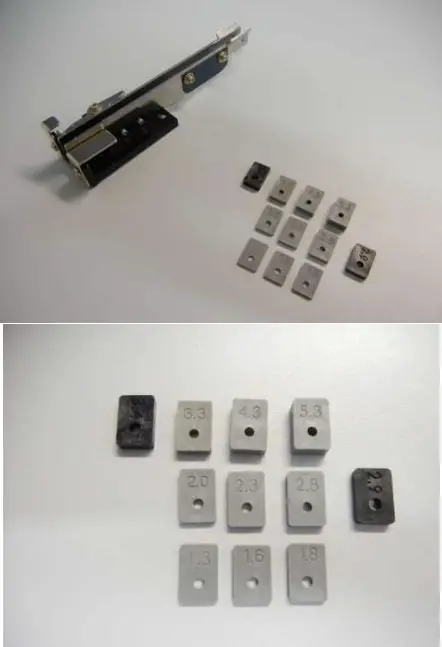 Procedure.
Remove the front panel as previously explained (see Bit guide regulation).
To remove the track, it’s first necessary to enlarge the 2 gate lock screws. Loosen the i and L screws, then M and N screws up to a sufficient width to extract the track.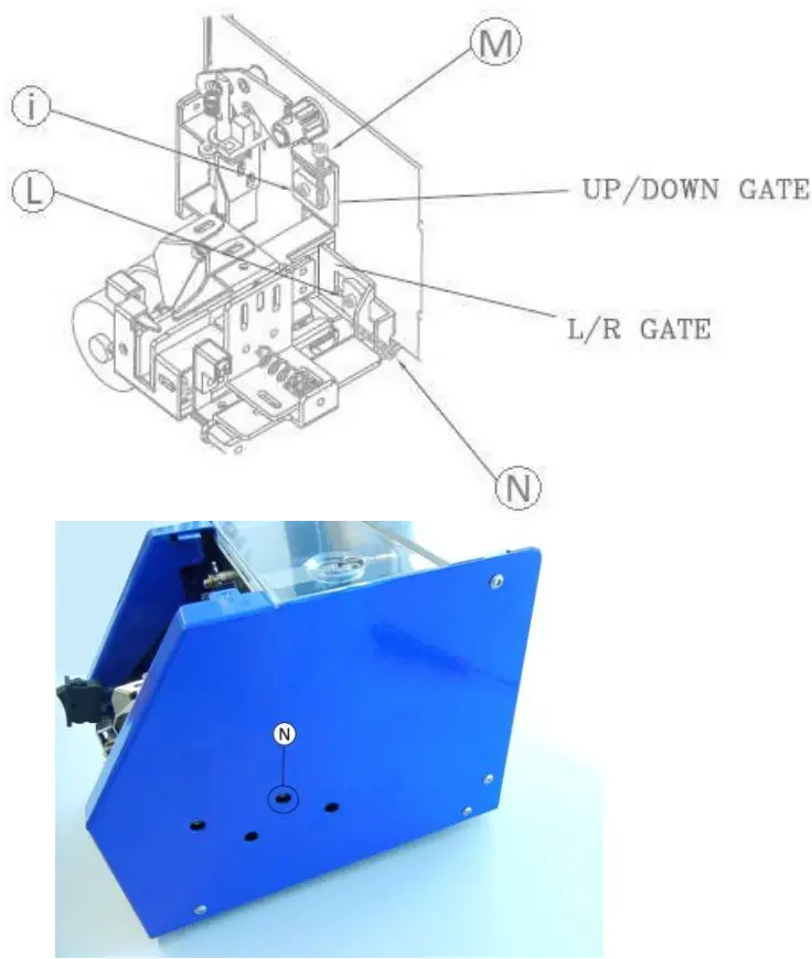 Loosen O screw and then extract the track.
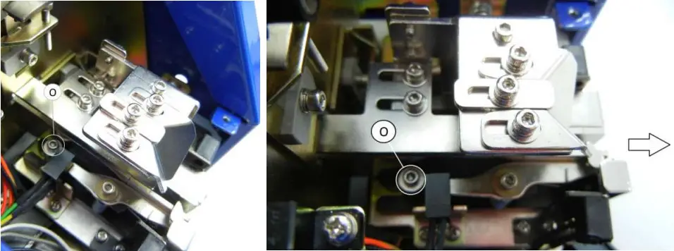 After removing the track and choosing the 2 spacers suitable to the screw used, loosen P and Q screws, and unscrew R screw.
Replace the spacer and tighten the screw R staring the new one at an angle of about 30 °. At the same time enter the second spacer at end of the track as a reference for the distance between the two plates, then tighten P and Q screws.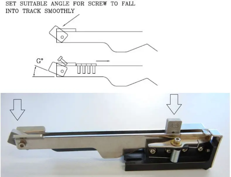
Reassemble the track, tighten O screw and closed the gates through M and N screws, clearance of 1 mm. Tighten i and L screw.
Adjust the bit guide and the cover track Each new shape screw
Troubleshooting.
| PROBLEM | CAUSE | COUNTERMEASURES |
| NFK does not turn ON | The AC/DC adapter is not connected to the power source | Connect the AC/DC adapter to the power source |
| The power switch is set on OFF | Set on ON the power switch | |
| NFK is set on ON but screws don’t exit | Screws not suitable | Check the screw size and properly calibrate the NFK |
| Track cover adjusted too low | Adjust the track cover again | |
| Exit speed too low | Increase the speed | |
| Foreign material inside the storage | Clean the storage and the track | |
| Screws stuck in the track | Brush, track, cover track in wrong position | Adjust them again |
Exploded view & spare list.
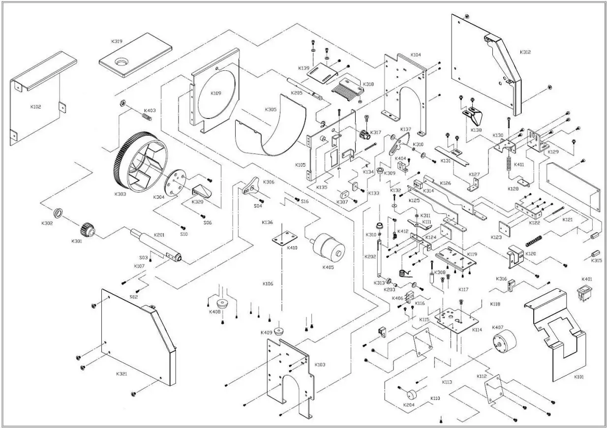
| RIF. | CODICE/CODE | DESCRIPTION |
| K101 | NFK-K101 | Front panel |
| K102 | NFK-K102 | Back panel |
| K103 | NFK-K103 | Rim board-left |
| K104 | NFK-K104 | Rim board-right |
| K105 | NFK-K105 | Front board |
| K106 | NFK-K106 | Base plate |
| K107 | NFK-K107 | Eccentric pulley fix board |
| K109 | NFK-K109 | Rear board |
| K110 | NFK-K110 | Mini motor fix board D |
| K111 | NFK-K111 | Wipe units |
| K112 | NFK-K112 | Mini motor fix steel board-rim (4) |
| K113 | NFK-K113 | Mini motor fix board |
| K114 | NFK-K114 | Track board-down |
| K115 | NFK-K115 | Sensor fix base-1 |
| K116 | NFK-K116 | Sensor fix base |
| K117 | NFK-K117 | Track base guide board |
| K118 | NFK-K118 | Sensor fix base-2 |
| K119 | NFK-K119 | Track base |
| K120 | NFK-K120 | Block board-front |
| K121 | NFK-K121 | M/C fix board |
| K122 | NFK-K122 | Track connectiong board-1 |
| K123 | NFK-K123 | Track board-front (2) |
| K124 | NFK-K124 | Track connectiong board-1 |
| K125 | NFK-K125 | Track board-right |
| K126 | NFK-K126 | Track board-left |
| K127 | NFK-K127 | Block board connectiong board |
| K128 | NFK-K128 | Spring fix board |
| K129 | NFK-K129 | Bit guide fix board |
| K130 | NFK-K130 | Bit guide fix upper board |
| K131 | NFK-K131 | Block board |
| K132 | NFK-K132 | Sensor fix base-5 |
| K133 | NFK-K133 | Sleeve fix board-1 |
| K134 | NFK-K134 | Adjust board |
| K135 | NFK-K135 | Adjust board |
| K136 | NFK-K136 | Mini motor fix board-1 |
| K137 | NFK-K137 | 45 teeth-M1 |
| K138 | NFK-K138 | Bit guide |
| K139 | NFK-K139 | Rocking fix board |
| K201 | NFK-K201 | Spin spindle |
| K202 | NFK-K202 | Rocking main spindle |
| K203 | NFK-K203 | Stud-4 |
| K204 | NFK-K204 | Eccentric pulley |
| K205 | NFK-K205 | Rocking main spindle |
| K301 | NFK-K301 | 20 teeth-M1 |
| K302 | NFK-K302 | Bush-1006 |
| K303 | NFK-K303 | Roller |
| K304 | NFK-K304 | Inside fix board |
| K305 | NFK-K305 | Inner board |
| K306 | NFK-K306 | Eccentric pulley-3 |
| K307 | NFK-K307 | Washer (2) |
| K308 | NFK-K308 | Sleeve |
| K309 | NFK-K309 | Bush-0606 (2) |
| K310 | NFK-K310 | Stud (2) |
| K311 | NFK-K311 | Stud |
| K312 | NFK-K312 | Outer board-right-manual |
| K313 | NFK-K313 | Sheave-1 |
| K314 | NFK-K314 | Kit of Spacers (18) |
| K315 | NFK-K315 | M/C fix board rod |
| K316 | NFK-K316 | Sensor-1 (2) |
| K317 | NFK-K317 | 11 teeth-M1 |
| K318 | NFK-K318 | Wipe units |
| K319 | NFK-K319 | Outer board-up |
| K320 | NFK-K320 | Load board |
| K321 | NFK-K321 | Outer board-left-manual |
| K401 | NFK-K401 | Start button | |
| NFK-K402 | Power supply | ||
| K403 | NFK-K403 | Power socket | |
| K404 | NFK-K404 | Sensor | |
| K405 | NFK-K405 | Mini-motor A (reducer) | |
| K406 | NFK-K406 | Sensor | |
| K407 | NFK-K407 | Mini-motor B | |
| K408 | NFK-K408 | Cushion-8 (2) | |
| K409 | NFK-K409 | Cushion-6 (2) | |
| K411 | NFK-K411 | Spring (0,8-1,0x28L) | |
| K412 | NFK-K412 | Torque spring (Ø0,5&0,6xØ8) | |
| K416 | NFK-K416 | Main board | |
| S01 | NFK-S01 | Cross round head+spring washer+washer (16) | M2,6×0,45Px4,5L |
| S02 | NFK-S02 | Cross pan head+spring washer (13) | M3x0,5Px6L |
| S03 | NFK-S03 | Cross pan head (6) | M3x0,5Px6L |
| S04 | NFK-S04 | Cross flat head (4) | M3x0,5Px8L |
| S05 | NFK-S05 | Cross pan head+spring washer+washer (63) | M2,6×0,45Px4,5L |
| S06 | NFK-S06 | Cross pan head+spring washer+washer (4) | M2,6×0,45Px10L |
| S07 | NFK-S07 | Cross pan head+spring washer+washer (2) | M2,6×0,45Px12L |
| S08 | NFK-S08 | Cross pan head+spring washer+washer (12) | M2,6×0,45Px6L |
| S09 | NFK-S09 | Cross pan head+spring washer (2) | M3x0,5Px15L |
| S10 | NFK-S10 | Cross flat head (6) | M2,6×0,45Px8L |
| S11 | NFK-S11 | Hex socket+spring washer+washer (10) | M2,6×0,45Px5,5L |
| S12 | NFK-S12 | Hex socket+spring washer+washer (2) | M2,6×0,45Px8L |
| S13 | NFK-S13 | Hex socket | M2,6×0,45Px20L |
| S14 | NFK-S14 | Hex socket | M2,6×0,45Px28L |
| S15 | NFK-S15 | Hex socket | M2,6×0,45Px38L |
| S16 | NFK-S16 | Cross flat head (3) | M3x0,5Px5L |
| S17 | NFK-S17 | Hex nut (2) | M2,6×0,45P |
| S18 | NFK-S18 | E type knob | ext. Ø6 |
| S19 | NFK-S19 | Hex socket conicity | M3x0,5Px4L |
| S20 | NFK-S20 | E type knob | ext. Ø3 |
| S21 | NFK-S21 | Hex socket (2) | M2,6×0,45Px20L |
| S22 | NFK-S22 | Washer (4) | 3×8 |
DECLARATION OF CONFORMITY
![]() KOLVER S.r.l.
KOLVER S.r.l.
VIA MARCO CORNER, 19/21
36016 THIENE (VI) ITALIA
Declare that the new tool here described:
Automatic screw feeder:
| NFK N14 | 14514 |
| NFK N17 | 14517 |
| NFK N23 | 14523 |
| NFK N26 | 14526 |
| NFK N30 | 14530 |
| NFK N40 | 14540 |
| NFK N50 | 14550 |
Is in conformity with the following standards and other normative documents: 2006/42/CE, LVD 2014/35/UE, EMCD 2014/30/UE, EN 62841-2-2:2014, EN 62841-1: 2015, EN 60204-1, EN 61000-6-2, EN 61000-6-4.
It is also in conformity with RoHS III normative (2011/65/UE and following 2015/863).
Name: Giovanni Colasante
Position: General Manager
Person authorized to compile the technical file in Kolver
Thiene, 1° gennaio 2021
Vers. 280421
![]() AUTOMATIC SCREW FEEDER /RS
AUTOMATIC SCREW FEEDER /RS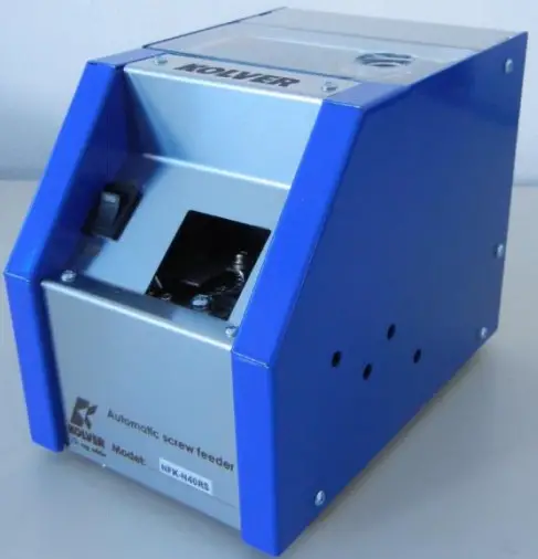
Features
Adjustable for a wide range.
The NFK/RS screw feeder can handle wide range of screws, e.g. metric or self-tapping screws, between M1 and M5 and 20 mm max length.
Working smoothly
The NFK/RS can work continuously without interruptions or jams thanks to the particular loading circuit and to the movement of the brush. Any screw in the wrong position falls in the screw storage so the loading cycle can restart.
Adjustable speed
It’s possible to adjust the vibration speed and the speed of the brush / loading wheel. Different combinations of speed allow to adapt the NFK to different works.
Use
The NFK/RS can easily be used on automatic machines thanks to the release of a single screw one by one. Moreover on the back panel there is a contact of screw presence.
General instructions
Before performing any such task, please read carefully these instructions and save them for future reference.
NFK/RS Accessories.
The NFK/RS package contains:
- 1 x NFK/RS already adjusted at the size required
- 1 x Instructions manuals
- 1 x AC/DC adapter + power cord
- 1 x male jack for the output signal connection
- 1 x hexagonal key

General precautions.
Install the NFK/RS in a stable horizontal position: an inclined base can affect the correct output of the screws. Improper installation could cause the NFK/RS to fall or jam.
Workplace.
Do not operate in presence of oil smoke, steam, moisture or dusts. It may occur fire or electric shock.
Cleaning.
Keep clean the lubricated parts and check them periodically.
Keep the screw storage clean and be careful of possible foreign material inside. Regularly inspect the rail.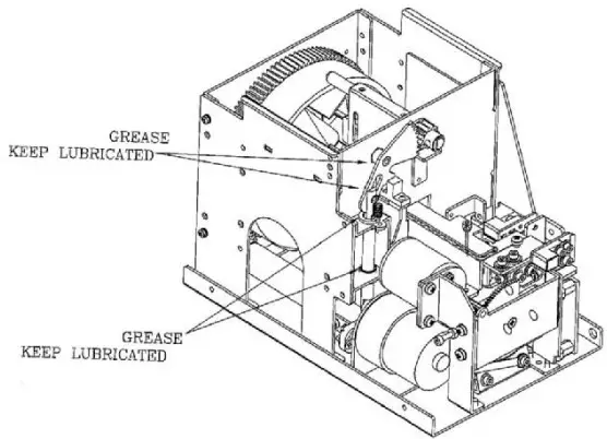 AC/DC Adapter.
Do not use any AC/DC adapter other than the specific one. It may occur fire or electric shock.
Rail.
Handle the rail carefully. It does not need to be lubricated but cleaned periodically. The dirt can block the screw flowing.
Picking up the screws.
Do not exert any force to pick up the screw. Excessive force could break or hit the unit.
Screw.
Do not use dirty or greasy screws, all dirt can clog the NFK/RS. Use only suitable screws (see Technical Data). Do not overfill the storage, the correct amount is described here below.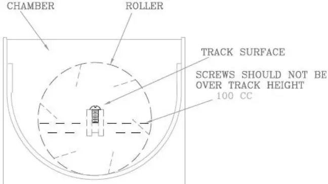 Covers.
Before any performance, make sure that all the covers are closed and secure.
IMPORTANT: Switch off the NFK before opening the covers.
When the NFK is off.
Disconnect the AC/DC adapter, when the unit is not used for an extended period of time.
WARNING.
When an abnormality occurs, stop immediately, turn off the power and unplug the power cord of the unit. Contact your Kolver dealer immediately.
Mechanical description
Technical data
Screw: Suitable for every head shape
D: Head diameter
A: Shank length
L: Total lenghtVoltage: 12V DC 500mA
Tension: IN 100/240 AC
OUT 12V DC 1,25A
Dimensions: 184 x 123 x 148 mm (L*W*H)
Weight: 2,75 Kg
Storage temperature: from 0°C to +50°C
Adjustments
Brush adjustment.
The eject brush places the screws that flows along the track and throws the ones in the wrong position in the storage.Procedure:
To adjust the eject brush height, loosen the screws in the picture below, raise or lower the brush to the height of the head of your screw.If the brush has been set too high, screws in the wrong position could pass and stop the passage. If too low, the brush could get stuck.
Procedure:
Remove the front and the lateral panel by unscrewing the screws as in the picture below and by slipping off the power button.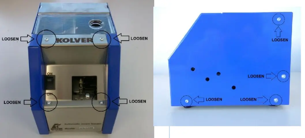 To adjust the height of the cover track block, loosen A screws and turn the B screw clockwise to lower, and counterclockwise to raise it. Once you have found the right spot tighten A screws.
The right height of the cover track from the head of the screw is 2/3 mm approx.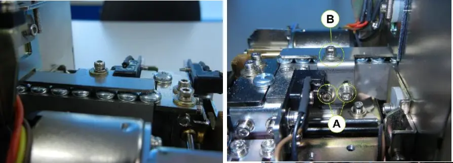 Speed adjustment.
To adjust the vibration speed and the speed of movement of the brush/ loading wheel depends on the use and on the type of screw.
C trimmer adjusts the vibration speed, while D trimmer adjusts simultaneously the speed of the brush and of the wheel of charge. For both the trimmer, if turned clockwise, the speed increases, anticlockwise it decreases.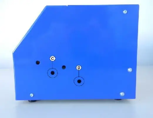 After the adjustments, reassemble the NFK/RS. Make sure that all screws are tightened properly.
Options
Signal on the rear panel.
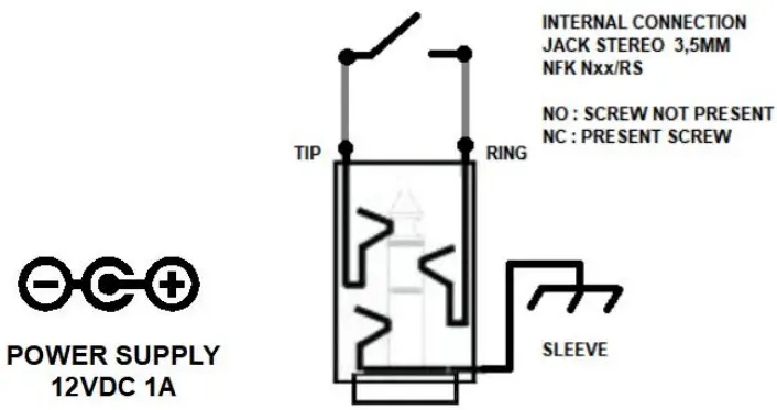
On the rear panel of the NFK/RS, near the power supply connector, there is a jack power connector (used with the supplied connector).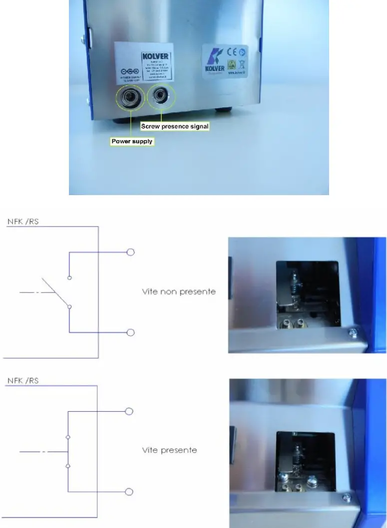
The jack power connector will give a relay contact (10A 250VAC or 30VDC): open contact is case of missing screw and closed contact in case of screw loaded.
Troubleshooting.
| PROBLEM | CAUSE | COUNTERMEASURES |
| NFK does not turn ON | The AC/DC adapter is not connected to the power source | Connect the AC/DC adapter to the power source |
| The power switch is set on OFF | Set on ON the power switch | |
| NFK is set on ON but screws don’t exit | Screws not suitable | Check the screw size and properly calibrate the NFK |
| Track cover adjusted too low | Adjust the track cover again | |
| Exit speed too low | Increase the speed | |
| Foreign material inside the storage | Clean the storage and the track | |
| Sensors not aligned | Check sensor alignment | |
| Screws stuck in the track | Brush, track, cover track in wrong position | Adjust them again |
I/O CONNECTIONS
On the back connector, it’s possible to get the signal of screw present. The contact is “normally” open (screw not present) and closed (screw present).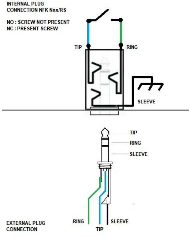
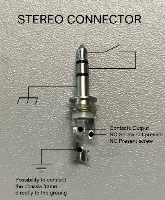
As you can see from the picture below, on the back panel of the NFK Nxx RS, there is a 3.5 mm female jack connector in which it is possible to bring out the clean contact of an internal relay (10A 250VAC or 30VDC).
Using a stereo connector from the TIP and RING contacts it is possible to obtain the screw presence contact.
Since the SLEEVE pin is directly connected to the chassis, if you want to ground the NFK Nxx RS, it is necessary to connect the SLEEVE pin directly to ground as shown below.
ATTENTION: Never connect the SLEEVE pin to the power supply otherwise also the NFK chassis will be under tension, creating possible short circuits with robots or other device that will come into contact with the chassis itself.
SN. 1917352
KOLVER
Kolver s.r.l.
Via M Corner n°19
36016 Thiene (VI) Italy
Tel. +39 0445 371068
www.kolver.it
[email protected]
DECLARATION OF CONFORMITY
![]() KOLVER S.r.l.
KOLVER S.r.l.
VIA MARCO CORNER, 19/21
36016 THIENE (VI) ITALIA
Declare that the new tool here described:
Automatic screw feeder:
| NFK N30/RS | Cod. 014530/RS |
| NFK N40/RS | Cod. 014530/RS |
| NFK Nxx/RS | Cod. 0145xx/RS |
Is in conformity with the following standards and other normative documents: 2006/42/CE, LVD 2014/35/UE, EMCD 2014/30/UE, EN 62841-2-2:2014, EN 62841-1: 2015, EN 60204-1, EN 61000-6-2, EN 61000-6-4.
It is also in conformity with RoHS III normative (2011/65/UE and following 2015/863)
Name: Giovanni Colasante
Position: General Manager
Person authorized to compile the technical file in Kolver
Thiene, 1° gennaio 2021![]()
Vers. 031120
![]() UNIVERSAL AUTOMATIC SCREW FEEDER
UNIVERSAL AUTOMATIC SCREW FEEDER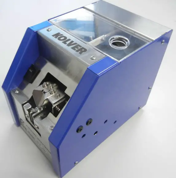
Features
Adjustable for a wide range.
This automatic screw feeder can handle wide range of screws, e.g. metric or self-tapping screws, between M1 and M5 and 20 mm max length.
Working smoothly
The NFK can work continuously without interruptions or jams thanks to the particular loading circuit and to the movement of the brush. Any screw in the wrong position falls in the screw storage so the loading cycle can restart.
Adjustable speed
It’s possible to adjust the vibration speed and the speed of the brush / loading wheel. Different combinations of speed allow to adapt the NFK to different works.
General instructions
Before performing any such task, please read carefully these instructions and save them for future reference.
NFK Accessories.
The NFK package contains:
- 1 x NFK already adjusted at the sizerequired
- 1 x Instruction manual
- 1 x AC/DC adapter + power cord
- 1 x hexagonal key

General precautions.
Install the NFK in a stable horizontal position: an inclined base can affect the correct output of the screws. Improper installation could cause the NKF to fall or jam.
Workplace.
Do not operate in presence of oil smoke, steam, moisture or dusts. It may occur fire or electric shock.
Cleaning.
Keep clean the lubricated parts and check them periodically.
Keep the screw storage clean and be careful of possible foreign material inside. Regularly inspect the rail.
AC/DC Adapter.
Do not use any AC/DC adapter other than the specific one. It may occur fire or electric shock.
Rail.
Handle the rail carefully. It does not need to be lubricated but cleaned periodically. The dirt can block the screw flowing.
Picking up the screws.
Do not exert any force to pick up the screw. Excessive force could break or hit the unit.
Screw.
Do not use dirty or greasy screws, all dirt can clog the NFK. Use only suitable screws (see Technical Data). Do not overfill the storage, the correct amount is described here below.Covers.
Before any performance, make sure that all the covers are closed and secure.
IMPORTANT: Switch off the NFK before opening the covers.
When the NFK is off.
Disconnect the AC/DC adapter, when the unit is not used for an extended period of time.
WARNING. When an abnormality occurs, stop immediately, turn off the power and unplug the power cord of the unit. Contact your Kolver dealer immediately.
Mechanical descriptionTechnical data
Screw: Suitable for every head shape
D: Head diameter
A: Shank length
L: Total lenght
Voltage: 12V DC 500mA
Tension: IN 100/240 AC OUT 12V DC 1,25A
Dimensions: 184 x 123 x 148 mm (L*W*H) Weight: 2,75 Kg
Storage temperature: from 0°C to +50°C
IMPORTANT: the item is not grounded!
In case it would be necessary, please connect an eyelet to a screw on the bottom.Adjustments
Brush adjustment.
The eject brush places the screws that flows along the track and throws the ones in the wrong position in the storage.Procedure:
To adjust the eject brush height, loosen the screws in the picture below, raise or lower the brush to the height of the head of your screw.If the brush has been set too high, screws in the wrong position could pass and stop the passage. If too low, the brush could get stuck.
Bit guide & track cover adjustment.
To pick the screw up, the bit guide should be centered on the screw head (see picture below). It’s also possible to adjust it right/left and forward/backward. The height of the track cover should be also adjusted so that only the screws in the correct position could go through it.Procedure:
To adjust the bit guide, loosen A screws.
Then find the correct position through the bit we will use and tighten A screws again.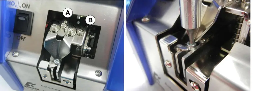 To adjust the height of the track cover/bit guide block, loosen C screws through D holes.
 Turn the B screw clockwise to decrease or counterclockwise to raise it. Once you have found the right spot, fix D screws.
The track cover/guide insert should be adjusted horizontally and parallel to the screw heads leaving a few millimeters apart as shown in the following figures.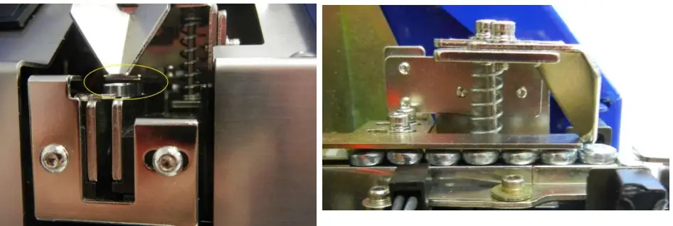 Speed adjustment.
To adjust the vibration speed and the speed of movement of the brush/ loading wheel depends on the use and on the type of screw.
M trimmer adjusts the vibration speed, while N trimmer adjusts simultaneously the speed of the brush and of the wheel of charge. For both the trimmer, if turned clockwise, the speed increases, anticlockwise it decreases.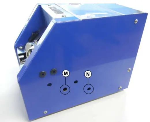
Track adjustment.
Track of NFK-UNI can be adjusted from M1 to M5 screws (1,4 ÷ 5,3 mm).
Procedure
Open the E gate (it could prevent the widening of the track), using F screw. Turn the screw clockwise to widen the gate and counterclockwise to close it.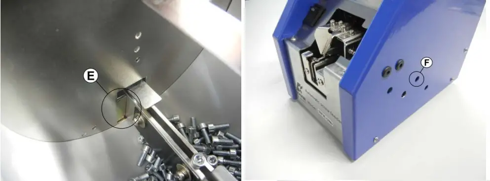 Loosen H and L screws, load in G and i two of the screws you’re going use. They will be a reference for the adjustments.
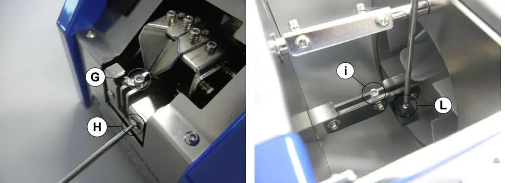 Bring near the 2 sides of the track with the help of your fingers until you find the correct distance of 0.3/0.5 mm larger than the diameter of the screw.
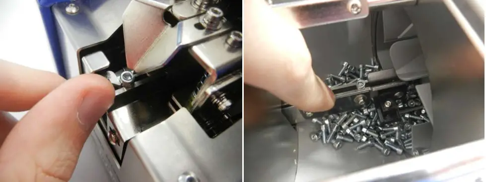 Tighten H and L screws. Slide a screw through the track: if it should not flow smoothly, repeat the procedure. a
Close E gate by turning counterclockwise F screw. Leave about 1 mm between the gate and the track.
Re-adjust the bit guide and the cover track each time you change screw type/size.
Troubleshooting.
| PROBLEM | CAUSE | COUNTERMEASURES |
| NFK does not turn ON | The AC/DC adapter is not connected to the power source | Connect the AC/DC adapter to the power source |
| The power switch is set on OFF | Set on ON the power switch | |
| NFK is set on ON but screws don’t exit | Screws not suitable | Check the screw size and properly calibrate the NFK |
| Track cover adjusted too low | Adjust the track cover again | |
| Exit speed too low | Increase the speed | |
| Foreign material inside the storage | Clean the storage and the track | |
| Screws stuck in the track | Brush, track, cover track in wrong position | Adjust them again |
Exploded view & spare list
| RIF. | CODICE/CODE | DESCRIPTION |
| K101 | NFK-K101 | Front panel |
| K102 | NFK-K102 | Back panel |
| K103 | NFK-K103 | Rim board-left |
| K104 | NFK-K104 | Rim board-right |
| K105 | NFK-K105 | Front board |
| K106 | NFK-K106 | Base plate |
| K107 | NFK-K107 | Eccentric pulley fix board |
| K109 | NFK-K109 | Rear board |
| K110 | NFK-K110 | Mini motor fix board D |
| K111 | NFK-K111 | Wipe units |
| K112 | NFK-K112 | Mini motor fix steel board-rim (4) |
| K113 | NFK-K113 | Mini motor fix board |
| K114 | NFK-K114 | Track board-down |
| K115 | NFK-K115 | Sensor fix base-1 |
| K116 | NFK-K116 | Sensor fix base |
| K117 | NFK-K117 | Track base guide board |
| K118 | NFK-K118 | Sensor fix base-2 |
| K119 | NFK-K119 | Track base |
| K120 | NFK-K120 | Block board-front |
| K121 | NFK-K121 | M/C fix board |
| K122 | NFK-K122 | Track connectiong board-1 |
| K123 | NFK-K123 | Track board-front (2) |
| K124 | NFK-K124 | Track connectiong board-1 |
| K125 | NFK-K125 | Track board-right |
| K126 | NFK-K126 | Track board-left |
| K127 | NFK-K127 | Block board connectiong board |
| K128 | NFK-K128 | Spring fix board |
| K129 | NFK-K129 | Bit guide fix board |
| K130 | NFK-K130 | Bit guide fix upper board |
| K131 | NFK-K131 | Block board |
| K132 | NFK-K132 | Sensor fix base-5 |
| K133 | NFK-K133 | Sleeve fix board-1 |
| K134 | NFK-K134 | Adjust board |
| K135 | NFK-K135 | Adjust board |
| K136 | NFK-K136 | Mini motor fix board-1 |
| K137 | NFK-K137 | 45 teeth-M1 |
| K138 | NFK-K138 | Bit guide |
| K139 | NFK-K139 | Rocking fix board |
| K201 | NFK-K201 | Spin spindle |
| K202 | NFK-K202 | Rocking main spindle |
| K203 | NFK-K203 | Stud-4 |
| K204 | NFK-K204 | Eccentric pulley |
| K205 | NFK-K205 | Rocking main spindle |
| K301 | NFK-K301 | 20 teeth-M1 |
| K302 | NFK-K302 | Bush-1006 |
| K303 | NFK-K303 | Roller |
| K304 | NFK-K304 | Inside fix board |
| K305 | NFK-K305 | Inner board |
| K306 | NFK-K306 | Eccentric pulley-3 |
| K307 | NFK-K307 | Washer (2) |
| K308 | NFK-K308 | Sleeve |
| K309 | NFK-K309 | Bush-0606 (2) |
| K310 | NFK-K310 | Stud (2) |
| K311 | NFK-K311 | Stud |
| K312 | NFK-K312 | Outer board-right-manual |
| K313 | NFK-K313 | Sheave-1 |
| K315 | NFK-K315 | M/C fix board rod |
| K316 | NFK-K316 | Sensor-1 (2) |
| K317 | NFK-K317 | 11 teeth-M1 |
| K318 | NFK-K318 | Wipe units |
| K319 | NFK-K319 | Outer board-up | |
| K320 | NFK-K320 | Load board | |
| K321 | NFK-K321 | Outer board-left-manual | |
| K401 | NFK-K401 | Start button | |
| NFK-K402 | Power supply | ||
| K403 | NFK-K403 | Power socket | |
| K404 | NFK-K404 | Sensor | |
| K405 | NFK-K405 | Mini-motor A (reducer) | |
| K406 | NFK-K406 | Sensor | |
| K407 | NFK-K407 | Mini-motor B | |
| K408 | NFK-K408 | Cushion-8 (2) | |
| K409 | NFK-K409 | Cushion-6 (2) | |
| K411 | NFK-K411 | Spring (0,8-1,0x28L) | |
| K412 | NFK-K412 | Torque spring (Ø0,5&0,6xØ8) | |
| K416 | NFK-K416 | Main board | |
| S01 | NFK-S01 | Cross round head+spring washer+washer (16) | M2,6×0,45Px4,5L |
| S02 | NFK-S02 | Cross pan head+spring washer (13) | M3x0,5Px6L |
| S03 | NFK-S03 | Cross pan head (6) | M3x0,5Px6L |
| S04 | NFK-S04 | Cross flat head (4) | M3x0,5Px8L |
| S05 | NFK-S05 | Cross pan head+spring washer+washer (63) | M2,6×0,45Px4,5L |
| S06 | NFK-S06 | Cross pan head+spring washer+washer (4) | M2,6×0,45Px10L |
| S07 | NFK-S07 | Cross pan head+spring washer+washer (2) | M2,6×0,45Px12L |
| S08 | NFK-S08 | Cross pan head+spring washer+washer (12) | M2,6×0,45Px6L |
| S09 | NFK-S09 | Cross pan head+spring washer (2) | M3x0,5Px15L |
| S10 | NFK-S10 | Cross flat head (6) | M2,6×0,45Px8L |
| S11 | NFK-S11 | Hex socket+spring washer+washer (10) | M2,6×0,45Px5,5L |
| S12 | NFK-S12 | Hex socket+spring washer+washer (2) | M2,6×0,45Px8L |
| S13 | NFK-S13 | Hex socket | M2,6×0,45Px20L |
| S14 | NFK-S14 | Hex socket | M2,6×0,45Px28L |
| S15 | NFK-S15 | Hex socket | M2,6×0,45Px38L |
| S16 | NFK-S16 | Cross flat head (3) | M3x0,5Px5L |
| S17 | NFK-S17 | Hex nut (2) | M2,6×0,45P |
| S18 | NFK-S18 | E type knob | ext. Ø6 |
| S19 | NFK-S19 | Hex socket conicity | M3x0,5Px4L |
| S20 | NFK-S20 | E type knob | ext. Ø3 |
| S21 | NFK-S21 | Hex socket (2) | M2,6×0,45Px20L |
| S22 | NFK-S22 | Washer (4) | 3×8 |
DECLARATION OF CONFORMITY ![]() KOLVER S.r.l.
KOLVER S.r.l.
VIA MARCO CORNER, 19/21
36016 THIENE (VI) ITALIA
Declare that the new tool here described:
Automatic screw feeder:
NFK-UNI: 014705
Is in conformity with the following standards and other normative documents: 2006/42/CE, LVD 2014/35/UE, EMCD 2014/30/UE, EN 62841-2-2:2014, EN 62841-1: 2015, EN 60204-1, EN 61000-6-2, EN 61000-6-4.
It is also in conformity with RoHS III normative (2011/65/UE and following 2015/863).
Name: Giovanni Colasante
Position: General Manager
Person authorized to compile the technical file in Kolver
Thiene, 1° gennaio 2021
Vers. 280421
![]()
NFK UNI Troubleshooting Guide
If the NFK UNI presents issues with not detecting when a screw is present/ not present at the front of the rail you can make the following adjustments after removing the front cover.
Adjusting the rail: Sometimes during shipping or initial set up the rail can move from the original pre-set position. Often the rail is too far out towards the front of the presenter and simply needs to be pushed back a small amount in order for it to properly line up with the sensors.
Rail:
 To adjust the rail, you want to loosen this screw:
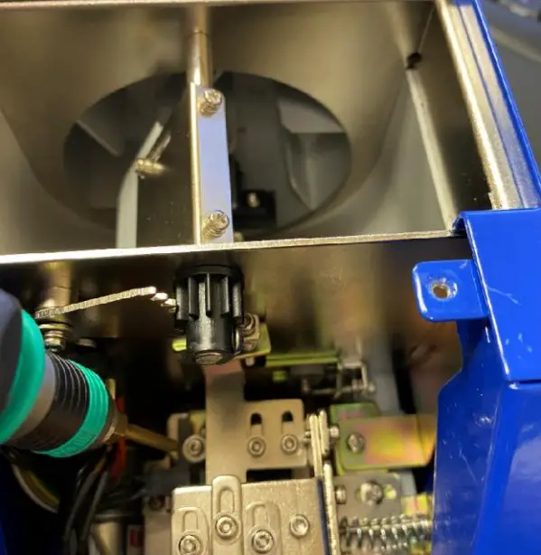 Once properly positioned fasten the screw again and turn the presenter on. If the issue continues you may need to adjust the sensors found on either side of the rail’s front section.
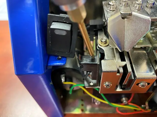 The sensors should be in matching positions on both side of the rail and aligned with the front portion of the rail where a screw rests after being fed.
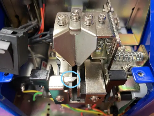 After this is complete turn the presenter back on and check to make sure the adjustments work
![]() Via Marco Corner, 19/21
Via Marco Corner, 19/21
36016 THIENE (VI) ITALIA
Tel. +39 0445 371068
Fax +39 0445 371069
[email protected]
www.kolver.it


