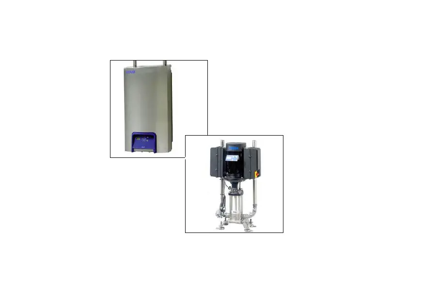
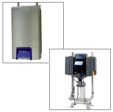
ECOLAB BW3 Booster Advanced
General information
For safety reasons, it is important to read all of the enclosed information ( Installation guide, Service manual, Spare parts, Operating instructions) before mounting this equipment.. In addition, the legislation in force at the time of purchase must always be considered in connection with the installation and mounting of this equipment, no matter the contents of this manual. If there are matters of a dispute please contact your dealer.
This equipment is produced and tested by specially qualified personnel, following approved instructions to ensure our high level of product qual- ity. After the product is finished and tested it is manually inspected with the ultimate test carried out just before the product is released for shipping. To obtain our high level of quality and long life we use stainless steel parts. These parts, in defiance of our manual inspections, may still have some
sharp edges, which can present a cut hazard. Therefore it is advised always to use protective gloves and show caution when installing the equipment.
Preparation Wall / Floor
If the wall is made of bricks or concrete, the enclosed screws and rawl plugs are usable, otherwise, you have to make sure that the carrying capacity of the wall is sufficient.
Note: The pipeline must be rinsed through before the system is connected. See service manual
Note: Remove cover before the system is mounted on the wall.
Placing/application
- Boosters must be placed in frost-free rooms only.
- Free space around the Booster: min 1500 mm.
Water supply
| BW3 | BW4 | BW8 | |
| Water volume | 100 l/min. | 135 l/min | 265 l/min |
| Pressure | 2 – 8 bar | 2 – 8 bar | 2 – 8 bar |
| Max. temperature | 70oC | 70oC | 70oC |
| BF3 | BF4 | BF8 | |
| Water volume | 100 l/min. | 135 l/min | 265 l/min |
| Pressure | 2 – 8 bar | 2 – 8 bar | 2 – 8 bar |
| Max. temperature | 70oC | 70oC | 70oC |
| BF16 | BF24 | |
| Water volume | 540 l/min. | 810 l/min |
| Pressure | 2 – 8 bar | 2 – 8 bar |
| Max. temperature | 70oC | 70oC |
The supply line must be sized so that it can supply the minimum indicated pressure and water volume when connected to this equipment.
Note: It is recommended to mount a mixing system on the water connection immediately before the outlet which is used.
Power supply
Connection instruction is mounted on the cables.
The phase order is subordinated.
Earth Leakage Circuit Breaker (ELCB).
When using an earth leakage circuit breaker (ELCB) also known as a residual current device (RCD) or a residual current circuit breaker (RCCB) in a system that incorporates a variable speed drive connected to 3 phase 400 V.
The trip level of the ELCB has to be 300 mA (30 mA used in the household will malfunction due to earth leakage) NB! Installation must always be in accordance with local legislation.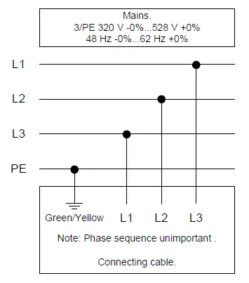
| BW3 | BW4 | BW8 | |
| Voltage: | 3/PE 400/480 V 320 -0%…528 +0% | 3/PE 400/480 V 320 -0%…528 +0% | 3/PE 400/480 V 320 -0%…528 +0% |
| Frequenz: | 50/60 Hz 48 -0%…62 +0% | 50/60 Hz 48 -0%…62 +0% | 50/60 Hz 48 -0%…62 +0% |
| Motor load: | 4 kW | 5.5 kW | 11 kW |
| Nominal current: | 10.6 A | 14.2 A | 27 A |
| Fuse: | 16 A | 20 A | 35 A |
| L1, L2, L3, PE | 2.5 mm2 | 2.5 mm2 | 6 mm2 |
| BF3 | BF4 | BF8 | |
| Voltage: | 3/PE 400/480 V 320 -0%…528 +0% | 3/PE 400/480 V 320 -0%…528 +0% | 3/PE 400/480 V 320 -0%…528 +0% |
| Frequenz: | 50/60 Hz 48 -0%…62 +0% | 50/60 Hz 48 -0%…62 +0% | 50/60 Hz 48 -0%…62 +0% |
| Motor load: | 4 kW | 5.5 kW | 11 kW |
| Nominal current: | 10.6 A | 14.2 A | 27 A |
| Fuse: | 16 A | 20 A | 35 A |
| L1, L2, L3, PE | 2.5 mm2 | 2.5 mm2 | 6 mm2 |
| BF16 | BF24 | |
| Voltage: | 3/PE 400/480 V 320 -0%…528 +0% | 3/PE 400/480 V 320 -0%…528 +0% |
| Frequenz: | 50/60 Hz 48 -0%…62 +0% | 50/60 Hz 48 -0%…62 +0% |
| Motor load: | 22 kW | 33 kW |
| Nominal current: | 54 A | 81 A |
| Fuse: | 70 A | 125 A |
| L1, L2, L3, PE | 16 mm2 | 25 mm2 |
Piping
The piping system should be made of stainless steel. It should always be possible to dismantle the pipe joints in connection with repair work, dis-placement etc. The dimensions stated below are only intended as a guide.
Calculations on a new pipe installation should always be based on pressure loss tables for pipes and fittings.
| Pipe connections | BW3 | BW4 | BW8 |
| Recommended pipe dimensions | 5/4″ | 5/4″ | 2″ * |
| Pipe dimensions unit | 5/4″ | 5/4″ | 5/4″ |
| Pipe connections | BF3 | BF4 | BF8 |
| Recommended pipe dimensions | 5/4″ | 5/4″ | 2″ * |
| Pipe dimensions unit | 5/4″ | 5/4″ | 5/4″ |
| Pipe connections | BF16 | BF24 |
| Recommended pipe dimensions | 2 1/2″ | 3″ |
| Pipe dimensions unit | 2 1/2″ | 3″ |
To ensure an always sufficient water flow and a minimum pressure loss, we recommend using a 2” pipe connection.
Always take into consideration, when planning and carrying out a new installation, that the pipe connection of the unit is 5/4”.
Note: A 5/4” – 2” closing valve must be mounted on the water supply im- mediately before the booster unit.
Assembly
Professional:
We recommend mounting the unit at a suitable height (approx 1 m above floor level) on a brick or concrete wall according to mounting instructions on Attach the wall bracket. Afterward, lower the booster unit onto the wall fittings.
Advanced:
We recommend mounting the unit in a suitable height (approx. 1 m above floor level) on brick or concrete wall.
In order to ease the mounting, we recommend making a mark on the wall and on the cabinet according to fig. 4. Then lift the booster unit until the mark on the cabinet flush with the mark on the wall. Now lower the booster onto the wall fittings.
Always use suitable attachment items in order to secure the main station. For mounting on brick or concrete walls please use the screws and raw plugs enclosed.


