![]()
Armis AR7 Full Tower housing
Installation Guide
Accessories
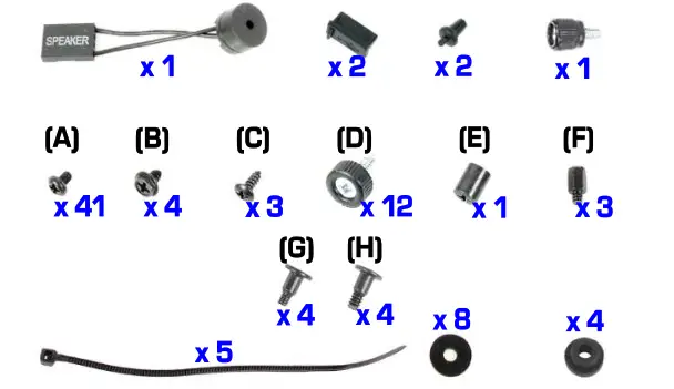
Mounting set and screws
HDD #1, #2
Open side panel
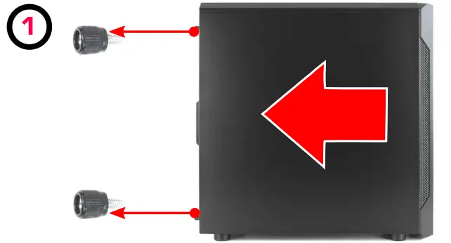
Unscrew and slide the side panel back
HDD #1, #2
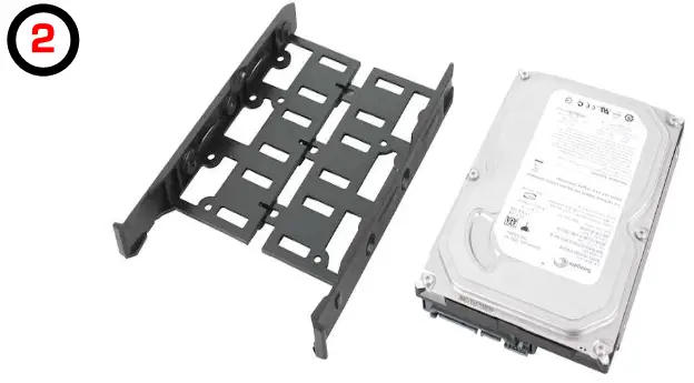 |  |
| Insert the HDD into the dedicated mounting tray | Slide the HDD into the HDD cage and secure it using (DJ screw |
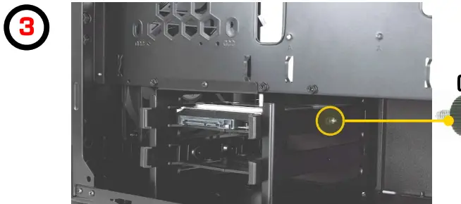
PUS
 | 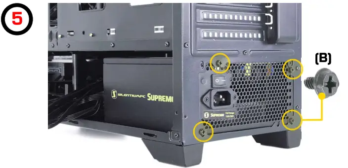 |
| Position the PSU on the bottom of the case with the fan facing downwards | Secure the PSU with (B) screws |
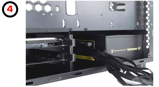
| EPS cable | ATX cable |
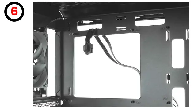 | 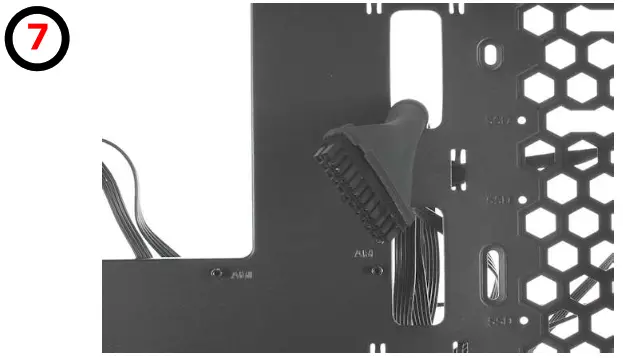 |
| Lead the EPS cable through the dedicated hole | Lead the ATX cable through the dedicated hole |
| Motherboard | Cable manag. |
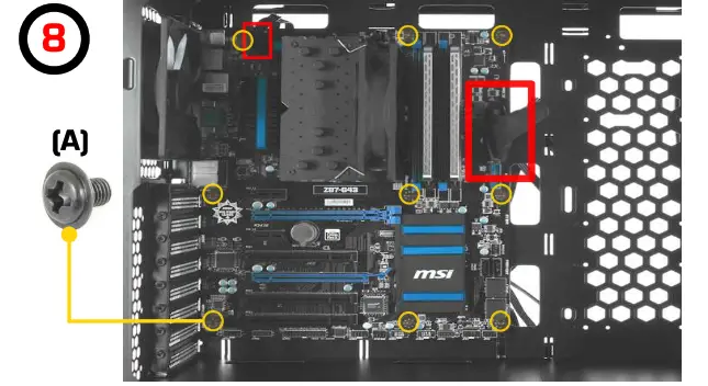 | 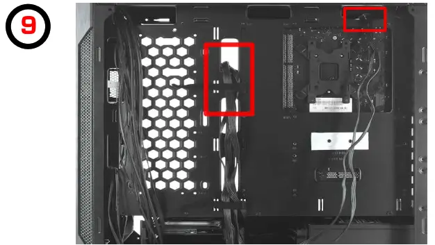 |
| Install the motherboard’s I/O shield, put the motherboard on standoffs, secure it with (Al screws, and then plug EPS and ATX cable | Cable management for EPS and ATX cable |
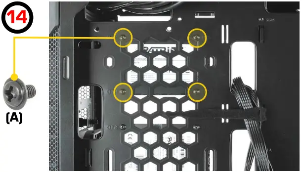
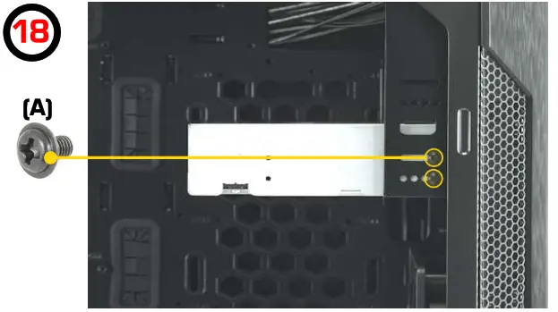
SSD #1, #2
 | 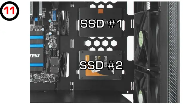 |
| Secure the SSD in a dedicated place using four screws (A) | SSD #1 and SSD #2 location |
SSD#3
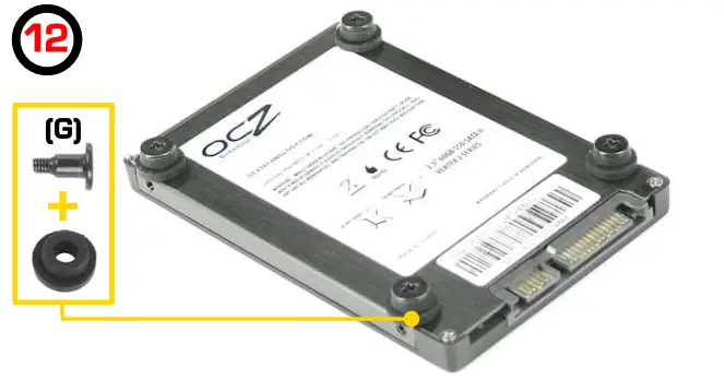 | 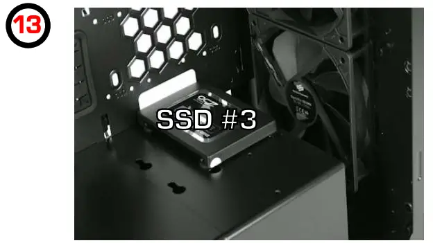 |
| Install dedicated (G) screw with pads | SSD #3 location |
SSD#4
 | 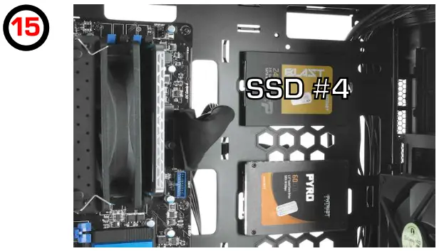 |
| AUDIO | USB 3.0 |
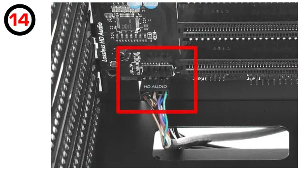 | 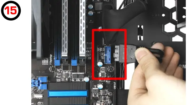 |
| Plug in the audio connector to the motherboard | Plug-in USB 3.0 connector to the motherboard |
GPU
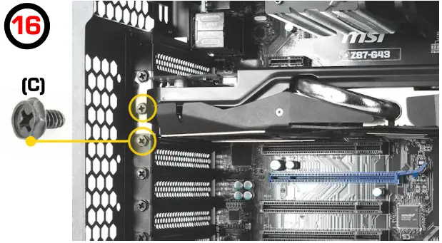 | 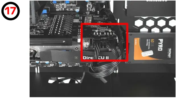 |
| Install the GPU in the PCI-E slot on the motherboard and secure it with (C) screws | Plug in the PCI-E connectors to the GPU |
ODD
 Remove the front 5.25″ drive bay cover, then slide the ODD into the drive bay and secure it with screws (A)
Optional fans
| Top fans (120 mm) | Top fans (140 mm) |
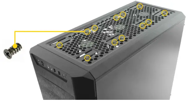 | 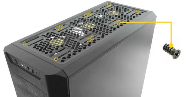 |
Additional features
| Fan controller | Fan controller |
 | 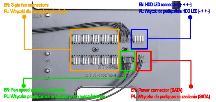 |
| Built-in fan controller for up to 10 fans in total | Fan controller connectors |
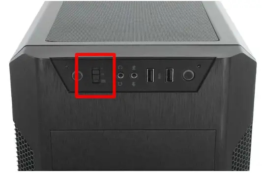
| Fan controller | Blackout feature |
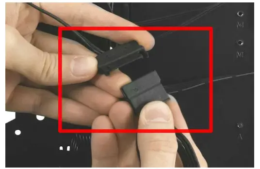 | 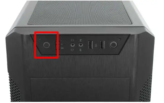 |
| Plug the power connector from the fan controller into the SATA connector from the PSU | Push to turn off LED within the I/O panel |
| Audio and USB ports covers | Front dust filters |
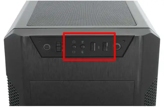 | 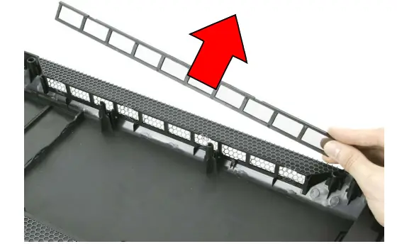 |
| Dust-proof covers for USB and audio ports | Front dust filters are removable and very easy to clean |
PUS cover
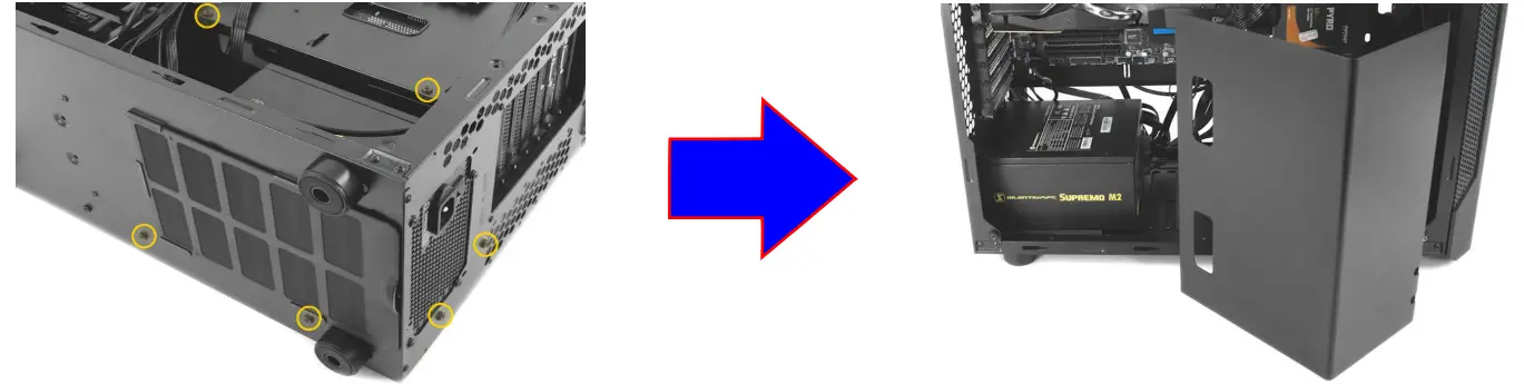
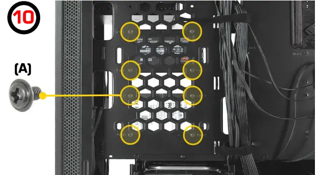
HDD cage
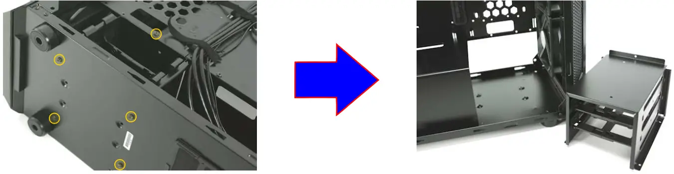
Unscrew the HCO cage (there are five screws securing it)
HDD module is removable
I/O panel swap
| I/O panel swap | I/O panel swap |
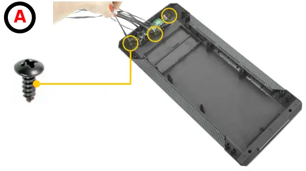 | 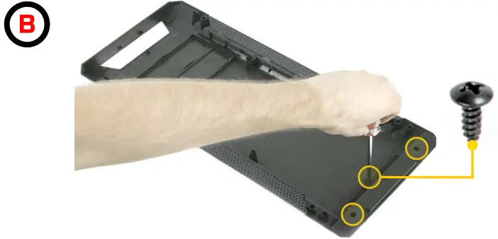 |
| Unscrew the I/O panel PCB (there are three screws securing it) and remove it | Remove the cover from the bottom of the front (unscrew three screws) |
| I/O panel swap | I/O panel swap |
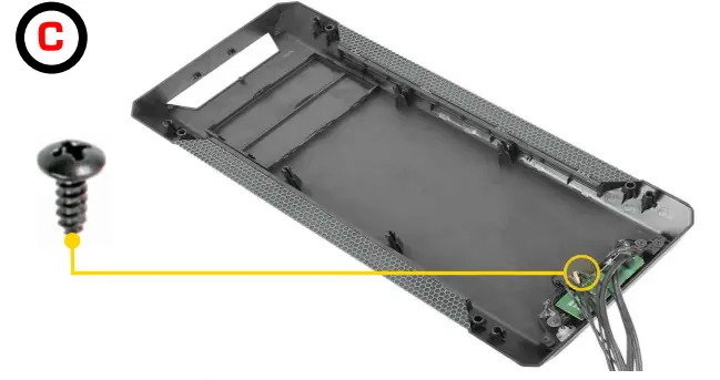 | 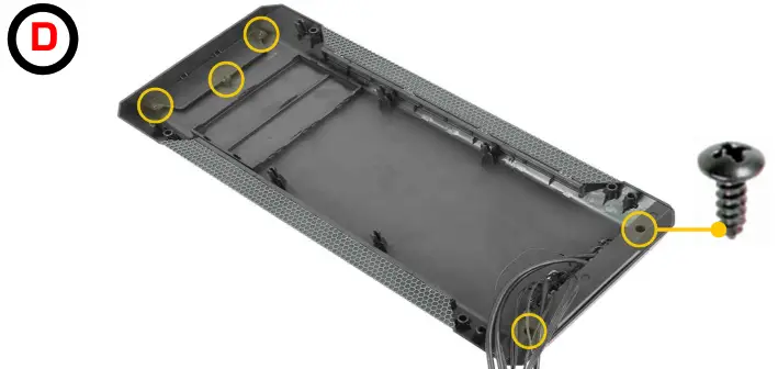 |
| Place I/O panel PCB in a new place and secure it with one screw | Place covers and secures them with screws (three screws for the upper cover and two screws for the bottom cover) |
| I/O panel swap | 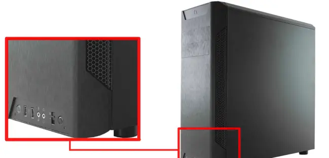 |


