
Endress Hauser FTS20 Liquifloat Point Level Switch Instruction Manual
Safety instructions
The FTS20 floating switch may only be used as a level limit switch in suitable liquids. Improper use may cause dangerous situations. The instrument may only be installed, connected and commissioned by qualified and authorised personnel, paying particular attention to:
- this compact manual
- the appropriate standards
- the statutory regulations and
- certificates (depending on version and application)
Safety symbols
![]() Warning!
Warning!
“Warning” indicates an action or procedure which, if not performed correctly, can result in injury or a safety hazard. Read the instructions thoroughly and proceed carefully.
![]() Note!
Note!
“Note” indicates processes which – if improperly executed – could affect operation or trigger unexpected instrument actions.
Instrument variants
| Order Code | Cable length | Type of switch | ||
| N A M U R | Initiator with switching ball for use in explosion-hazardous areas 2-wire to EN 60947-5-2 (NAMUR)Use with isolating amplifier; ATEX II 2 G Ex ia IIB T5 Gb | |||
| 5201011971035516 | 5 m20 m | With PVC cable material (black) | ||
| 5201012071035517 | 5 m20 m | With PUR cable material (gray) | ||
| 5201012171035518 | 5 m20 m | With CSM cable material (black) | ||
| Warning!NAMUR device versions: if using accessories in hazardous areas, their use must be assessed by the user. | ||||
| A C / D C | Microswitch with switching ball for standard application,3-wire, change-over contact for max. 250 V AC / 150 V DC | |||
| 5201012271035520 | 5 m20 m | |||
| 5201012371035521 | 5 m20 m | |||
| 5201012471035522 | 5 m20 m | |||
| Accessories | ||||
| Nivotester FTL325N | Isolating amplifier | |||
| 52010125 | Compression gland G1A, PVC | |||
| 52010126 | Counter nut G1A, PVC | |||
| 52010127 | Weight (coated with polyamide) Warning! The weight No. 52010127 may not be used in hazardous areas. | |||
Function
An element built into the floating switch switches when a deviation in the horizontal is detected. The switching process is triggered by the movement of a steel ball and, depending on the version, is carried out by an inductive initiator or a microswitch. The inductive initiator acts as a switching output and provides a switching signal to EN 60947-5-2 (NAMUR). The microswitch version is a two-way switch.
Features
- Reliable level limit detection in liquids
- Electrical connections to NAMUR for hazardous areas (to Zone 1) or change-over contact (AC/DC) for universal standard application
- Different cable materials for different media
- Small diameter for simple installation using tapped hole G1A
Applications
Controlling pumps and valves with one switch or signal level height or limit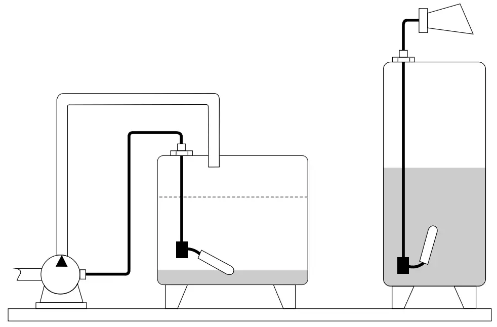
Installation
The floating switch can be installed as follows:
- The floating switch can be inserted into the tank – through a tapped hole G1A – and screwed to the compression gland (G1A).
- If it is installed from above, use the weight.
![]() Note!
Note!
- The fulcrum of the cable should always be horizontal.
- The cable length between the fixture and the floating body is dependent on the cable type (see “Technical data”).
- When using the weight, place an extra strain relief (e.g. a knot in the cable) behind the compression gland – on the outside of the tank.
Electrical connection
![]() Warning!
Warning!
Note the switch type!
| Inductive proximity switch with switching ball (NAMUR)Order codes: 52010119, 5201012052010121, 7103551671035517, 71035518 | 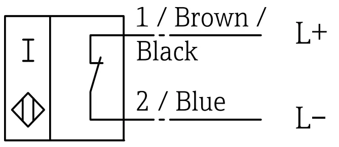 | Connection indication L+ = black or brownL- = blue(closing when floating) |
| Change-over contact (AC/DC)Order codes: 52010122, 5201012352010124, 7103552071035521, 71035522 | 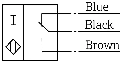 | Cable colours:black + brown = contact open blak + blue = contact closed (contact position when floating) |
Technical data FTS20 (NAMUR)
| Measuring system | Comprising an FTS20 floating switch and an isolating amplifier, e.g.Endress+Hauser Nivotester FTL325N | |||
| Switching element | Inductive proximity switch with switching ball, closed when floating | |||
| Power supply | 8.2 V ±2 V | |||
| Operating current | <1.2 mA unswitched; >2.1 mA switched | |||
| Reverse polarity protection | Yes | |||
| Switching angle | Switching points: top +15° ±5°, bottom +15° ±5°, measured to the horizontal | |||
| Process temperature range | Dependent on cable material: PVC and PUR: +5…+70 °C, CSM: –20…+70 °C | |||
| Ingress protection | DIN EN 60529, IP68 (immension depth: 20 m / without temporal limit) | |||
| Process pressure | £ 3 bar at 20 °C | |||
| Density of liquid | ³ 0.8 g/cm3 | |||
| Floating body material | Polypropylene (PP) | |||
| Cable material | PVC, CSM: standard length 5 m and 20 m, cross section 2 x 0.75 mm2 PUR: standard length 5m and 20 m, cross section 2 x 0.50 mm2 | |||
| Minimum cable length between fixing and floating body | PVC: ³ 50 mmPUR: ³ 100 mm CSM: ³ 100 mm | |||
| Ex approval | TÜV 99 ATEX 1709 | |||
| Ex ingress protection | 0 II 2G Ex ia IIB T5 Gb | |||
| Temperature class Ambient temperature Voltage CiCurrent Ii Power Pi Inductance Li Capacitance Ci | T4-20 °C…+70 °C16 V72 mA242 mW1 mH153 nF | T5-20 °C…+40 °C16 V72 mA242 mW1 mH153 nF | T5-20 °C…+55 °C16 V52 mA208 mW1 mH153 nF | T5-20 °C…+70 °C16 V52 mA180 mW1 mH153 nF |
| Standards | EN 60947-5-2:2007 +A1:2012; EN 60079-0:2012 + A11:2013; EN 60079-11:2012 | |||
Technical data FTS20 (AC/DC)
| Measuring system | Comprising an FTS20 floating switch |
| Switching element | Microswitch with switching ball |
| Switching function | Change-over contact |
| Switching voltage | AC: max. 250 V; DC: max. 150 V |
| Switching current | Max. 3 A (AC), max. 1 A (DC) |
| Switching angle | Upper switching point: +25° ±10°Lower switching point: –14° ±10°, measured to the horizontal |
| Process temperature range | Dependent on cable material:PVC and PUR: +5…+70 °C, CSM: –20…+70 °C |
| Ingress protection | DIN EN 60529, IP68 (immension depth: 20 m / without temporal limit) |
| Process pressure | £ 3 bar at 20 °C |
| Density of liquid | ³ 0.8 g/cm3 |
| Floating body material | Polypropylene (PP) |
| Cable material | PVC, CSM: standard length 5 m and 20 m, cross section 3 x 0.75 mm2 PUR: standard length 5m and 20 m, cross section 3 x 0.50 mm2 |
| Minimum cable length between fixing and floating body | PVC: ³ 50 mm PUR: ³ 100 mm CSM: ³ 100 mm |
Dimensions
FTS20 floating switch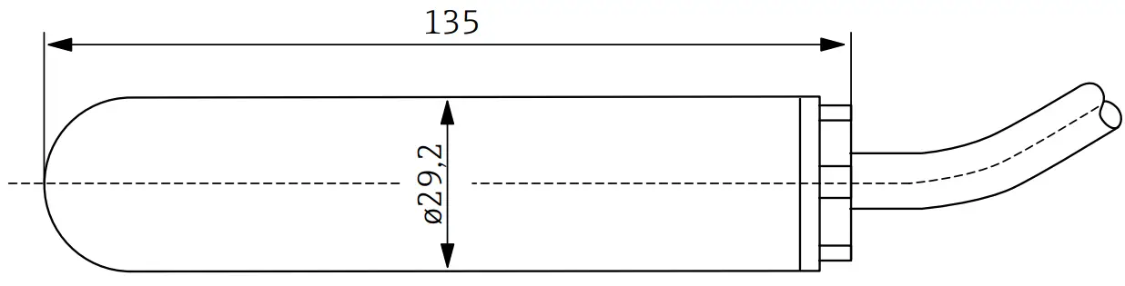
Compression gland weight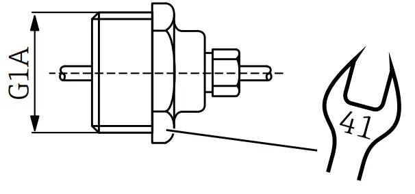
Weight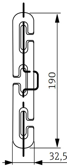
(Dimensions in mm)


