![]() User’s Manual
User’s Manual
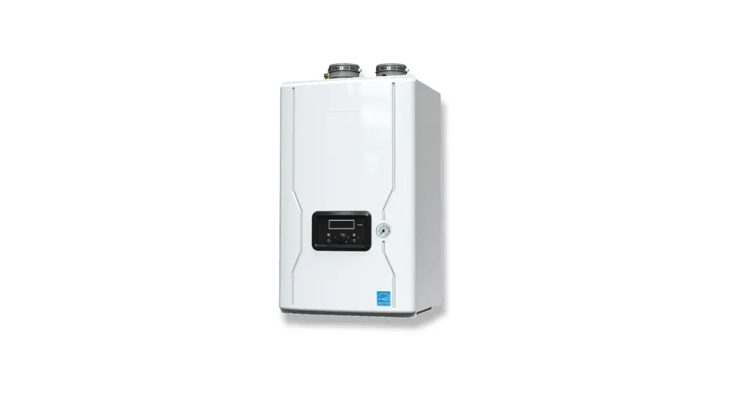
THE FT SERIES
Wall-Mounted, Modulating
Gas, Condensing, Combination BoilerModel FTCW
140,000 BTU/h
199,000 BTU/h
• Natural Gas (NG) – Factory Configuration
• Propane Gas (LP) – Field-Convertible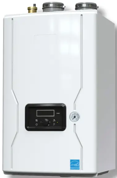
FOR YOUR SAFETY: This product must be installed and serviced by a professional service technician, qualified in hot water boiler and heater installation and maintenance. Improper installation and/or operation could create carbon monoxide gas in flue gases which could cause serious injury, property damage, or death. Improper installation and/or operation will void the warranty.
![]() WARNING
WARNING
If the information in this manual is not followed exactly, a fire or explosion may result causing property damage, personal injury, or loss of life.
Do not store or use gasoline or other flammable vapors and liquids in the vicinity of this or any other appliance.
WHAT TO DO IF YOU SMELL GAS
- Do not try to light any appliance.
- Do not touch any electrical switch; do not use any phone in your building.
- Immediately call your gas supplier from a nearby phone. Follow the gas supplier’s instructions.
- If you cannot reach your gas supplier, call the fire department.
Installation and service must be performed by a qualified installer, service agency, or gas supplier.
Familiarizing yourself to
THE FT SERIES
The FT Series Combi is a wall-mounted, condensing, and fully modulating, residential boiler and water heater.
This User’s Manual will guide you into the basics of operating your FT Series Combi.
Please reference the Installation and Operation Manual for complete details. Doc# 1487
Caring For Your FT
Your FT Series Combi will require very little maintenance. However, as with any fine appliance, there are certain steps that should be taken to ensure continuing optimum performance.
2.1 General Care
Keep the area around the FT Series Combi clean and free from combustible materials, gasoline, and other flammable liquids and vapors.
The FT Series Combi must be completely isolated and protected from any source of corrosive chemical fumes such as trichloroethylene, perchloroethylene, chlorine, etc.
Keep bottom and top openings on the boiler free for proper ventilation of interior components.
Do not obstruct or block a free flow of air to the boiler to ensure proper ventilation.
If desired, clean the jacket surfaces with a damp cloth and mild detergent. Do not use flammable cleaning materials.
If sidewall vented, keep the vent terminal clear of obstructions — do not allow snow to cover the vent terminal. Clean the intake screen often, and then develop an appropriate maintenance schedule.
2.2 Annual Inspection of Flue and Vents
Visually inspect the vent pipe once a year. Should any deterioration exist, have the affected parts replaced by a qualified service person.
2.3 In the event of a Power Failure
The FT Series Combi can not be operated during an electrical power outage. If there is an extended power outage with the danger of freezing, then the FT Series Combi (and all other water systems) should be drained completely. When draining the boiler, turn off the main electrical disconnect switch. When placing back in service, refer to Section 3 of this Manual for instruction.
All draining and filling must only be done by a qualified service person.
2.4 Full Service Every Year
In addition to the annual visual inspections, a qualified service agency should conduct a detailed inspection of all flue product carrying areas of the FT Series Combi and its venting system.
User’s Manual – The FT Series Wall Mounted, Combination Boiler
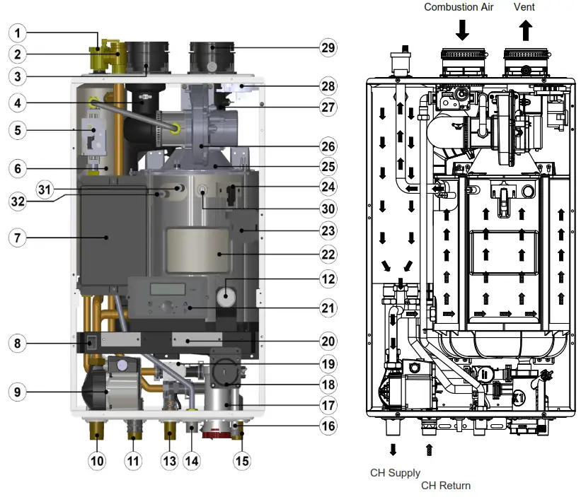 | |||
| # | Name of Component | # | Name of Component |
| 1 | Air Vent (air eliminator) | 17 | Condensate Trap |
| 2 | Pressure Relief Valve | 18 | Blocked Condensate Switch |
| 3 | Air Intake Collar | 19 | Mixing Valve |
| 4 | Air Gas Mixing Pipe | 20 | Terminal Block |
| 5 | Gas Valve | 21 | Control Panel and Display |
| 6 | DHW Water Tank | 22 | Heat Exchanger |
| 7 | Main PCB | 23 | Ignition Transformer |
| 8 | Manual Power Switch (ON / OFF) | 24 | Flame Detecting Sensor |
| 9 | Boiler Pump | 25 | Burner Case |
| 10 | ‘CH’ Supply Connection | 26 | BLDC Fan (Blower) |
| 11 | ‘CH’ Return Connection | 27 | Vent Pipe |
| 12 | CH Pressure Gauge | 28 | Air Pressure Sensor |
| 13 | DHW Outlet Connection | 29 | Vent Pipe Collar |
| 14 | Gas Inlet Connection | 30 | Sight Glass |
| 15 | DHW Inlet Connection (filter and flow restrictor) | 31 | Low Water Cut Off |
| 16 | Condensate Connection | 32 | Overheat Temperature Sensor |
Shut Down and Restart
3.1 To Start the FT Series Combi
If drained, please refer to the Install and Operating Manual to ensure that the complete ‘Setup’ procedure has been followed before starting this boiler. A complete ‘Setup’ must be performed by a qualified service person.
3.2 Shutting Down the FT Series Combi
- Turn off the main electrical disconnect switch.
- Close all manual gas valves.
- If freezing is anticipated, drain the FT Series Combi and be sure to also protect building piping from freezing. All water must be removed from heat exchanger and condensate trap or else damage from freezing may occur. Please refer to the Install and Operating Manual.
This step to be performed by a qualified service person. all Mounted, Combination Boiler
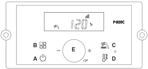
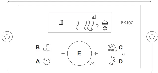
The Control Display and Operation
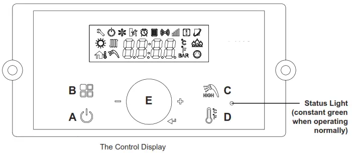
The Control Display has a Control Dial (E), 4 buttons (A, B, C, D), and a Liquid Crystal Display (with 72 back-lit segments). This section of this manual gives instructions on how to navigate into the many functions of the FT and to change temperature set points, set system variables, and controller parameters.
| Buttons | Function | Method | Function | Method | ||
| A | Display Power | Turns Control Display ON / OFF | Press/Tap | |||
| B | Modes | Status Display Mode (With display power on) | Press/Hold (5 Seconds) | Return to Menu (from Status Display Mode) | ||
| Installer Mode (WIth display power off ) | Press/Hold (5 Seconds) | Return to off display off mode (from installer mode) | Press/Tap | |||
| C |  | Hot Water | DHW Setpoint LOW Range 95 – 120°F (35 – 49°C) | Press/Tap (To return home, tap Scroll/Select) | DHW set point HIGHRange 121-140°F (49.560°C) (from DHW set point LOW RANGE) | Press/Tap |
| D |  | Central Heat | CH set point mode (boiler only) | Press/Tap (To return home, tap Scroll/Select) | Toggle (°C/°F) (from CH set point mode) | Press/Hold (5 Seconds), (To return home, tap Scroll/ Select) |
| E | Scroll / Select | Turn to scroll (clockwise or counterclockwise), Tap to select | Press/Tap | Press/Hold (5 Seconds) | ||
• Temperature Specifications
Operating Ambient Temperature Range: -10 to 60°C.
Operating Relative Humidity up to 90% at 40°C.
Shipping & Storage Temperature Range of -20 to 80°C.
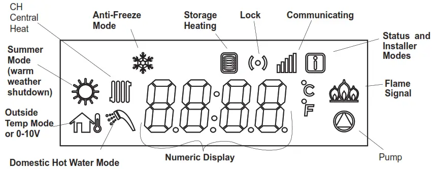
| CH mode | The Central Heat mode icon can be adjusted |
| Anti-freeze mode | Anti-freeze mode icon |
| Storage Heating mode | Stored Water Being Heated, can be adjusted |
| Lock mode | Buttons-locked mode icon |
| Communication | Communication icon |
| Summer mode | Only DHW Mode can be adjusted (warm weather shutdown) |
| Status and Installer mode | The Status Mode or the Installer Mode is Active (all parameters) |
| Flame signal | Flame Signal icon |
| Pump icon | Water pump operation (CH or DHW) icon |
| Numeric Display | Number and character display, to display all parameters |
| DHW mode | Combination boiler Set Point can be adjusted |
| Outside temp or 0-10 V mode | Operating by outside temperature or 0-10V |
The LCD will illuminate when a user action is detected (a button is pressed) and will turn back off after 20 seconds.
* NOTE: The display will not allow changes when the lock mode![]() is activated.
is activated.
To exit the Lock mode, press the![]() button.
button.
![]() WARNING
WARNING
Do no use this appliance if any part has been under water. Immediately call a qualified service technician to inspect the appliance and to replace any part of the control system and any gas control that may have been under water.
Operating Mode
Operating Mode
After the Power is turned on, and/or the Control Display is turned on,![]() the Control Display will go through a ‘Start Up’ checklist and briefly show a sequence of diagnostic codes before entering into the ‘Operating Mode. It will then display the following information.
the Control Display will go through a ‘Start Up’ checklist and briefly show a sequence of diagnostic codes before entering into the ‘Operating Mode. It will then display the following information.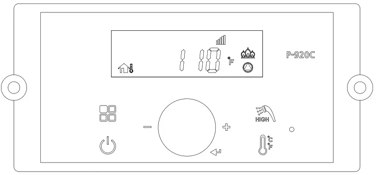
| Indicate | Example |
| Current Operating Temperature | 110°F |
| Temperature sign Celsius or Fahrenheit letter | °C or °F |
| The display and Controller are communicating | |
| If fl are detected | |
| If the pump is operating | |
| Outdoor sensor or 0-10V |
Status Display Mode
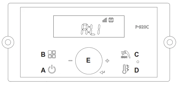
| Digital Display | Status Display Parameter | Description | ||||
| O:ot | Outdoor temperature | Current Outdoor temperature | ||||
| A: Li or A: GA | Flow unit | Current flow value(Li: Um, GA: GPM) | ||||
| b: It | CH Return Water Temperature | Current Return Water Sensor Temperature | ||||
| C: Fr | Fan rpm | The current fan rpm value | ||||
| d: Lc | Lock mode | Lock mode ON/OFF | ||||
| E:oP | OP temperature | Current OP temperature | ||||
| F:dH | DHW temperature | Current DHW temperature | ||||
| H: Eh | Exhaust temperature | Current Exhaust temperature | ||||
| I : St | N/A | Not Used (Default is 0) | ||||
| J: off | Overheat temperature | Current Overheat temperature | ||||
| L: rt | 1:PH | Burner Operation Time | Supply power time | Supply power time x 100 hour | ||
| Burner operation time | Burner operation time x 1 hour | |||||
| 2:rh | ||||||
| 3:rH | Burner operation time | Burner operation time x 1,000 hour | ||||
| 4:It | Ignition cycles | Ignition cycles x 10 times | ||||
| 5:IH | Ignition cycles | Ignition cycles x 10,000 times | ||||
| P: Ou | Displays output condition for internal primary pump and three-way valve. | 1st Icon | 2nd Icon | 3rd Icon | ||
| Not Used | Inte Pum Pump CH | 3 Way Valve | ||||
 | | |||||
To view any of the above-listed Status Parameters,
Press and Hold Button B ![]() to get into the Status Display Mode.
to get into the Status Display Mode.
Rotate Dial E until you fi nd the Parameter that you wish to view. Tap Dial E to enter that Parameter.
Adjust to the setting that you require and then press (tap) Dial E to save and to Exit.
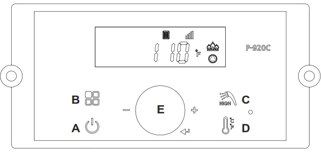
DHW Set Point Change Mode
DHW Set Point Change Modes The display shows the following information when changing water heating temperature set points.
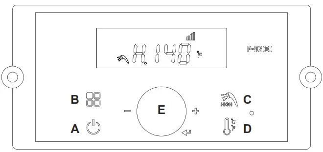
Changing between Celsius and Fahrenheit When the button D![]() is pressed (for more than 5 seconds), the temperature unit will toggle between °C and °F.
is pressed (for more than 5 seconds), the temperature unit will toggle between °C and °F.
| Indicate | Example |
| Current DHW set point temperature | 120°F |
| Temperature sign Celsius or Fahrenheit letter | °C or °F |
| If the display is communicating with the main controller normally, the communication icon will be indicated. | |
| When DHW set point range is high: from 121°F (49.5°C) to 140°F (60.0°C) | H . 140°F |
| When changing the DHW set point, the DHW icon will fl ash |
* Default DHW set point is 120°F (49°C)
- DHW 95-120°F (35 – 49°C) LOW range (Default)
-To change the LOW range, press the C Button. The DHW icon and current DHW LOW will fl ash (an fl ashing value means it can be changed).
-Turn dial E clockwise to increase and counterclockwise to decrease until the desired temperature is reached.
-Press dial E to save set point changes. - DHW 121 – 140°F (49.5 – 60°C) HIGH range
-To change the HIGH range, press and HOLD the C button for more than 5 seconds. The DHW icon and current DHW HIGH will fl ash (an fl ashing value means it can be changed).
-Turn dial E clockwise to increase and counterclockwise to decrease until the desired temperature is reached.
-Press dial E to save set point changes and to Exit.
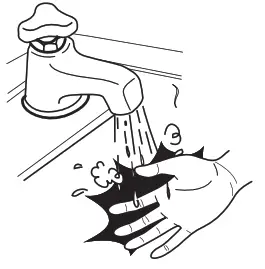
DANGER
Scalding may occur within 5 seconds at a setting of 140°F (60°C). Water temperatures over 125°F can cause severe burns or death from scalding. Children, the disabled, and the elderly are at the highest risk of being scalded. Read all instructions before setting the temperature at the appliance. Feel water before bathing or showering.
The manufacturer strongly recommends the use of an anti-scald mixing valve at a domestic hot water outlet (boiler location) to reduce the potential for scalding.
Contact Manufacturer for recommended models. Check with local codes.
CH Set Point Change Mode
Changing between Celsius and Fahrenheit When the button D![]() is pressed (for more than 5 seconds), the temperature unit will toggle between °C and °F.
is pressed (for more than 5 seconds), the temperature unit will toggle between °C and °F.
| Indicate | Example |
| Current Operating Temperature | 110°F |
| Temperature sign Celsius or Fahrenheit letter | °C or °F |
| The display and Controller are communicating | |
| If fl are detected | |
| If the pump is operating | |
| When changing the CH Setpoint, the CH Icon will fl ash |
The default CH set point is 130°F (54°C)
CH set point range is 130 – 180°F (54.4 ~ 82.0°C)
To change CH Setpoint, press the D![]() button. The CH Icon and current CH Setpoint will fl ash.
button. The CH Icon and current CH Setpoint will fl ash.
Turn the E dial clockwise to increase, and counterclockwise to decrease CH set point, until the desired temperature is reached.
Press the E dial to save changes and to Exit.
Storage Mode
| Indicate | Example |
| Current Operating Temperature | 110°F |
| Temperature sign Celsius or Fahrenheit letter | °C or °F |
| The display and Controller are communicating | |
| If fl are detected | |
| Storage mode indication | |
| If the Pump is operating |
To activate the heat storage function, First, turn OFF the power to the Control Display.
Then Press and Hold Button B![]() to get into the Installer Mode.
to get into the Installer Mode.
Rota te Dial E until you find 5:St Tap Dial E to enter Storage Mode. Storage Mode indicates that the boiler is maintaining the water temperature in the internal storage tank. When Storage Mode is active, the display will appear as shown.
Turn the E dial clockwise to activate and counterclockwise to deactivate the Heat storage function. Default: ON.
Press the E dial to save changes and to Exit.
Notes:————————————————————————————————————————————-
Dimensions and specifications are subject to change without notice in accordance with our policy of continuous product improvement.
![]() Customer Service and Product Support: 800.900.9276
Customer Service and Product Support: 800.900.9276
• Fax 800.559.1583
20 Industrial Way, Rochester, NH, USA 03867
H2412500-
20-10 Document 1488


