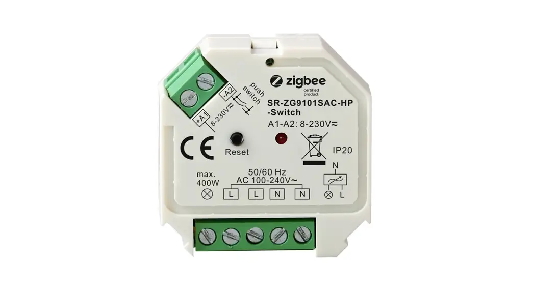
ZigBee 2-Gang In-wall Switch
![]()
Important: Read All Instructions Prior to Installation
Function introduction
Product Data
| Input Voltage | Output Voltage | Output Channel | Max. Load | Size(LxWxH) |
| 100-240VAC | 100-2A0VAC | 2 Channels | Resistive load: max. 5.1A1CH Capacitive load: max. 1.7A1CH | 45.5x45x20.3mm |
| Compatible Load Types | |||
| Load Symbol | Load Type | Maximum Load | Remarks |
| LED lamps with transformers | 390W/CH @ 230V 180W/CH @ 110V | Due to variety of LED lamp designs. maximum number of LED lamps is further dependent on power factor result when connected to switch. | |
| LED drivers | 390W/CH @ 230V 180W/CH @ 110V | Maximum permitted number of drivers is 390W divided by driver nameplate power rating. | |
| Incandescent lighting, HV Halogen lamps | 1170W/CH @ 230V 580W/CH @ 110V | ||
| Low voltage halogen lighting with electronic ansformers transformers | 390W/CH @ 230V 180W/CH @ 110V | ||
Over Current Protection
- When connecting resistive load and total load is over 8.1A, the relay will be forced to off and protected.
- 2-gang ZigBee in-wall switch based on latest ZigBee 3.0 protocol
- 100-240VAC wide input and output voltage
- Supports resistive loads and capacitive loads
- 2 channels output, max. load 5.1A/CH
- Input and output with screw terminals, safe and reliable
- Enables to control ON/OFF of connected load
- ZigBee device with 2 endpoints which can be controlled separately
- ZigBee end device that supports Touchlink commissioning
- Can directly pair to a compatible ZigBee remote via Touchlink without coordinator
- Supports self-forming zigbee network without coordinator and add other devices to the network
- Supports find and bind mode to bind a ZigBee remote
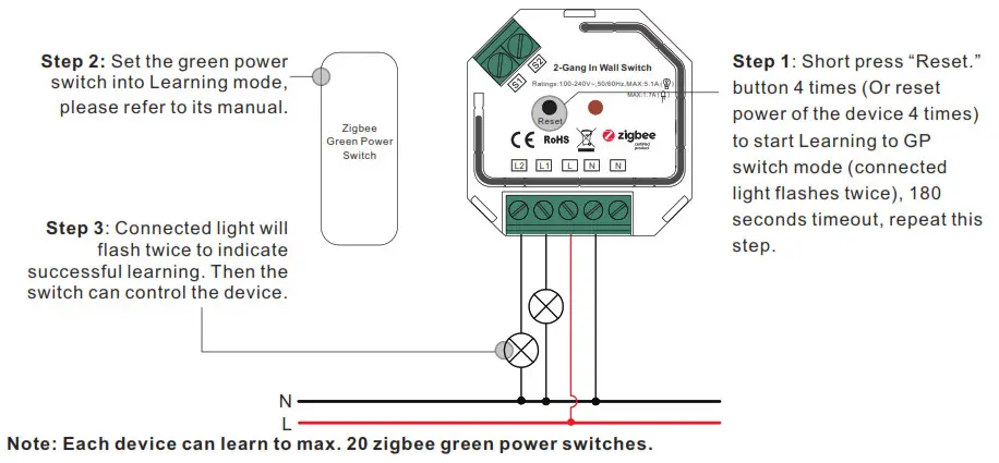
- Supports zigbee green power and can bind max. 20 zigbee green power switches
- Compatible with universal ZigBee gateway products
- Can be controlled by universal single wire push switch, 2 channels can be controlled separately by 2 switches
- Active power and energy metering functionality
- Mini Size, Easy to be installed into a standard wall box
- Radio Frequency : 2.4GHz
- Waterproof grade: IP20
Safety & Warnings
- DO NOT install with power applied to device.
- DO NOT expose the device to moisture.
ZigBee Clusters the device supports are as follows:
Input Clusters
- 0x0000: Basic
- 0x0003: Identify
- 0x0004: Groups
- 0x0005: Scenes
- 0x0006: On/off
- 0x0702: Simple Metering
- 0x0b04: Electrical Measurement
- 0x0b05: Diagnostics
Output Clusters
- 0x0019: OTA
Operation
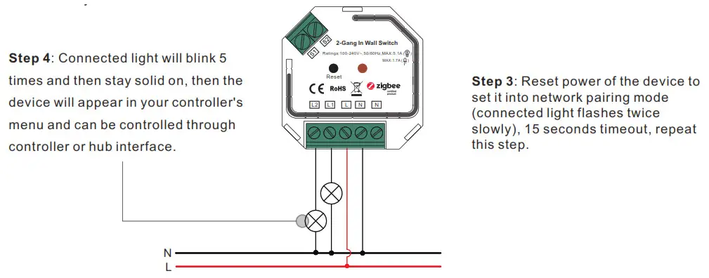
- Do wiring according to connection diagram correctly.
- This ZigBee device is a wireless receiver that communicates with a variety of ZigBee compatible systems. This receiver receives and is controlled by wireless radio signals from the compatible ZigBee system.
- Zigbee Network Pairing through Coordinator or Hub (Added to a Zigbee Network) Step 1: Remove the device from previous zigbee network if it has already been added to, otherwise pairing will fail. Please refer to the part “Factory Reset Manually”.
Step 2: From your ZigBee Controller or hub interface, choose to add lighting device and enter Pairing mode as instructed by the controller.
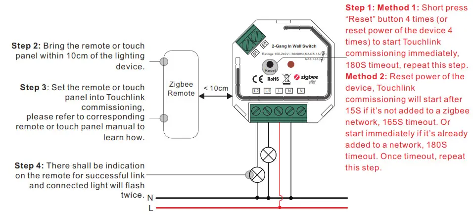
- TouchLink to a Zigbee Remote
 Note:
Note:
1) Directly TouchLink (both not added to a ZigBee network), each device can link with 1 remote.
2) TouchLink after both added to a ZigBee network, each device can link with max. 30 remotes.
3) To control by both gateway & remote, add remote and device to network first then TouchLink.
4) After TouchLink, the device can be controlled by the linked remotes. - Removed from a Zigbee Network through Coordinator or Hub Interface

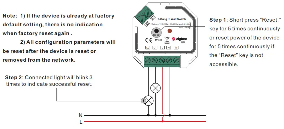
- Factory Reset Manually

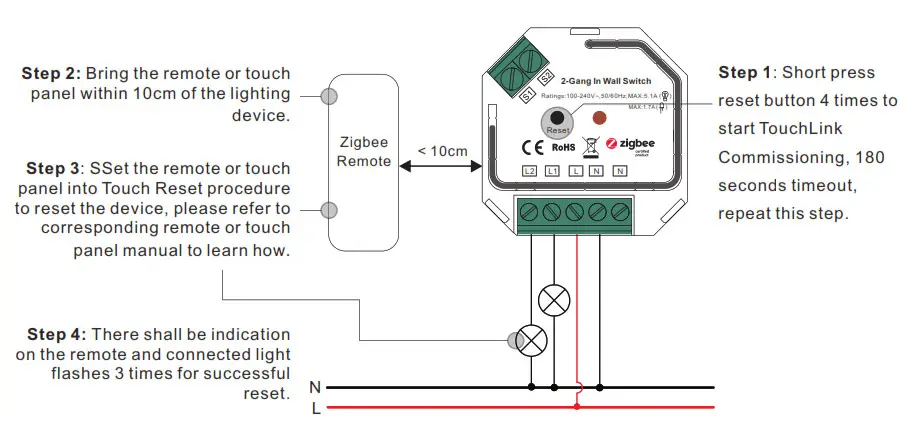
- Factory Reset through a Zigbee Remote (Touch Reset)
Note: Make sure the device already added to a network, the remote added to the same one or not added to any network.
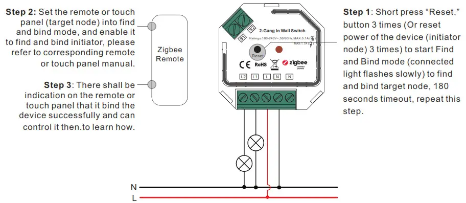
- Find and Bind Mode
Note: Make sure the device and remote already added to the same zigbee network.
- Learning to a Zigbee Green Power Switch

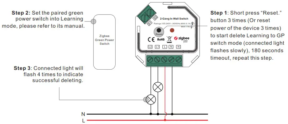
- Delete Learning to a Zigbee Green Power Switch

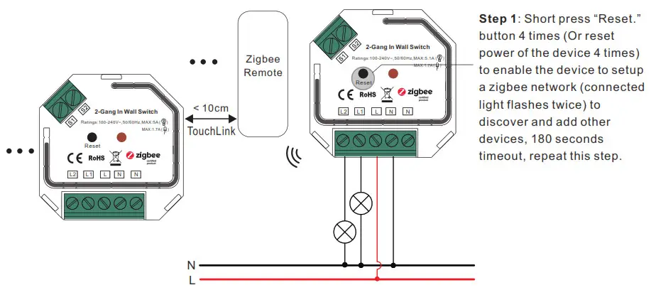
- Setup a Zigbee Network & Add Other Devices to the Network (No Coordinator Required)
 Step 2: Set another device or remote or touch panel into network pairing mode and pair to the network, refer to their manuals.
Step 3: Pair more devices and remotes to the network as you would like, refer to their manuals.
Step 4: Bind the added devices and remotes through Touchlink so that the devices can be controlled by the remotes, refer to their manuals.
Note:
1) Each added device can link and be controlled by max. 30 added remotes.
2) Each added remote can link and control max. 30 added devices. - OTA
The device supports firmware updating through OTA, and will acquire new firmware from zigbee controller or hub every 10 minutes automatically.
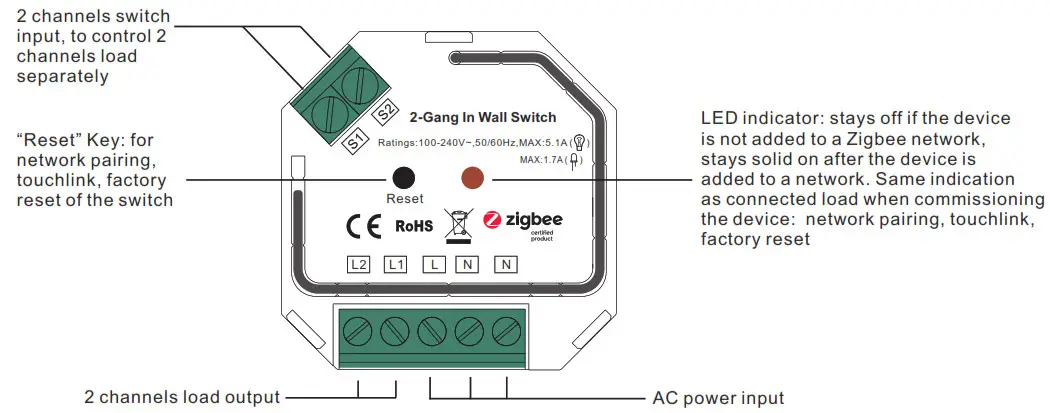
Wiring Diagram
Notes for the diagrams:
L – terminal for live lead
N – terminal for neutral lead
S1 – terminal for switch key No. 1
S2 – terminal for switch key No. 2
L1 – output terminal no. 1 for light load
L2 – output terminal no. 2 for light load Product Dimension
 Note:
Note: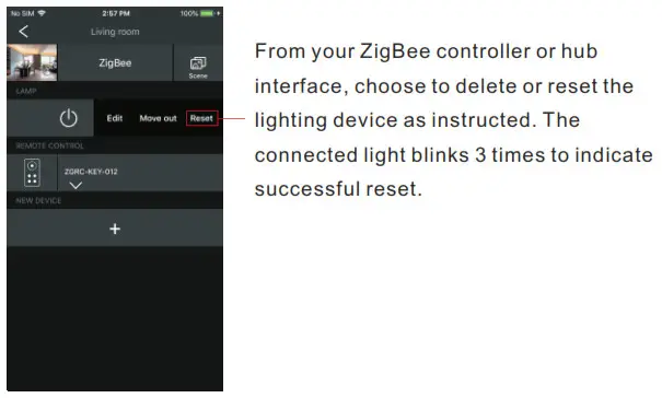
 Step 2: Set another device or remote or touch panel into network pairing mode and pair to the network, refer to their manuals.
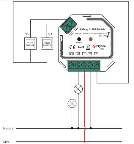 Product Dimension
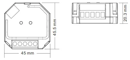


 Zigbee Rf Smart Ac Switch User Manual")


 Manual")


