
CLARKE1500 Ultra Speed Pro 1500 High-Speed Floor Burnisher

Product Information
The Ultra Speed Pro 1500 is a commercial floor machine designed for indoor use. It comes with a special grounding plug and must be grounded to reduce the risk of electrical shock. The machine is equipped with a handle release assembly that allows for safe and easy operation. The machine is not intended for any other use other than commercial use.
Safety Precautions
All operators must read and understand the following safety precautions before operating the machine:
- Do not operate the machine without reading the operator’s manual thoroughly.
- Do not operate the machine without using recommended accessories.
- Do not operate the machine if any damage is detected.
- Do not service the machine without following proper safety guidelines.
Machine Maintenance & Storage
After use, unplug the machine from the power source and wrap the cord around the handle. Tilt the machine so that the pad is not touching the floor and store it in an upright position in a dry area.
Operation of Speed Floor Machines
Follow these instructions carefully for the safe and effective operation of the Ultra Speed Pro 1500:
- Remove any obstructions or obstacles in the area that needs to be cleaned.
- Place the handle in the upright position and tilt the machine back until the handle rests on the floor.
- Attach the pad to the machine by unscrewing the male end of the big mouth from the flexible pad driver. Place the approved pad on the pad driver, place the male end of the big mouth into the center hole of the pad, and tighten the big mouth firmly to the pad driver.
- To adjust the handle height, lift up the compression handle located on the right side of the handle tube about 1 foot above floor level. Release the compression handle and adjust the handle to a safe operating height, then push back down on the compression handle to lock the handle in the operating position.
- Plug the power cord into a grounded outlet. Do not use an extension cord in conjunction with the standard power cord.
- Press the red safety button on the top of the machine to start it.
This book has important information for the use and safe operation of this machine. Failure to read this book prior to operating or attempting any service or maintenance procedure to your Clarke machine could result in injury to you or to other personnel; damage to the machine or to other property could occur as well. You must have training in the operation of this machine before using it. If your operator(s) cannot read this manual, have it explained fully before attempting to operate this machine.
All directions given in this book are as seen from the operator’s position at the rear of the machine.
SAFETY PRECAUTIONS
- This machine is intended for commercial use. It is constructed for use in an indoor environment and is not intended for any other use. Use only recommended accessories.
All operators shall read, understand and exercise the following safety precautions:
- Do not operate machine:
- Unless trained and authorized.
- Unless you have read and understand operators manual.
- In fl ammable or explosive areas.
- With damaged cord or plug.
- If not in proper operating condition.
- In outdoor areas.
- In standing water.
- With the use of extension cords.
- Before operating machine:
- Make sure all safety devices are in place and operate properly.
- When using machine:
- Only use approved burnishing pads.
- Do not run machine over cord.
- Do not pull machine by cord or plug.
- Do not pull cord around sharp edges or corners.
- Ensure the dust collection bag is in place and is tightly sealed to the machine.
- Turn power switch to “off “ prior to unplugging machine.
- Do not unplug by pulling on the cord.
- Do not stretch cord.
- Do not handle plug with wet hands.
- Keep cord away from heated surfaces.
- Do not pick up burning or smoking debris such as cigarettes, matches or hot ashes.
- Report machine damage or faulty operation immediately.
- Before leaving or servicing the machine:
- Turn off the machine.
- Unplug the cord from the outlet.
- When servicing the machine:
- An experienced technician should only perform service work.
- Unplug the cord from the outlet.
- Use manufacturer-supplied or approved replacement parts.
GROUNDING INSTRUCTIONS
This machine must be grounded! Grounding provides the path of least resistance for electrical current. To reduce the risk of electrical shock should the machine malfunction, the machine has a special grounding plug. Do not remove the ground pin under any circumstances! To avoid electrical shock, please replace the power cord immediately if any damage is being detected. The replacement must be performed only by an authorized person.
OPERATION OF SPEED FLOOR MACHINES
READ OPERATOR MANUAL THOROUGHLY PRIOR TO OPERATING OR SERVICING THIS MACHINE.
GENERAL USE
- Remove any obstructions or other obstacles in the area which is to be cleaned.
- Place the handle in the upright position and tilt machine back until handle rests on the floor
- Be sure the machine is not plugged into an outlet
- Attach the pad to the machine by fi rst unscrewing the male end of the “big mouth” from the fl exible pad driver. Place the approved pad on the pad driver, place the male end of the “big mouth” into the center hole of the pad, and tighten the “big mouth” fi rmly to the pad driver.
- Place machine back into its upright position.
- Plug power cord into a grounded outlet. * Never use an extension cord in conjunction with the standard power cord.
- The handle height may be adjusted by lifting up the compression handle which is located on the right side of the handle tube about 1 foot above fl oor level. Release the compression handle and adjust handle to safe operating height, then push back down on the compression handle to lock the handle in operating position.
- To start the machine, press the red safety button on the top of the upper switch housing, and then squeeze either of the operating triggers. (the safety button must be depressed prior to squeezing the operating triggers.)
- When the machine is in operation, both hands should be placed on the switch housing (upper handle).
- To stop the machine at any time, simply release the operating trigger(s) and the machine will stop automatically.
MAINTENANCE
- To keep this machine performing well for many years, please follow the following maintenance procedures:
- Always confi rm the machine is unplugged from the power source prior to performing any maintenance or repairs!
INSTRUCTIONS FOR USE
- Unplug machine as soon as you are done using it.
- Clean the outside of the machine with a mild cleaner.
- Check power cord for any damage. If damage is detected, replace power cord immediately.
- Lubricate wheels with a water resistant lubricant once a month.
- Check machine for loose or missing nuts and bolts, and replace as necessary.
- If the machine is used in a dusty environment, you may remove the motor cover and blow the motor clean with compressed air. This will ensure proper ventilation, and allow the motor to run cooler.
STORAGE
- Unplug machine from power source and wrap cord on handle.
- Tilt machine so the pad is not touching the fl oor.
- Store machine in upright position and in a dry area.
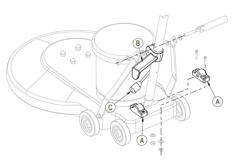
HANDLE RELEASE ASSEMBLY INSTRUCTIONS
STEP 1
- Remove nut and spacer from handle bracket assembly.
- Push the two handle brackets backward so they lean against the rear wheel.
STEP 2
- Remove Handle Clamp Blocks (A) with 5mm hex head.
- Place handle assembly into handle clamp blocks.
- Re-attach the blocks to the base with 5mm hex head.
STEP 3
- Make sure actual Cord Wrap (B) faces to the left of the machine when you are standing behind it.
- Assemble hardware in the following order; spacer, left handle bracket, nylock nut. (do not over tighten nylock nut. Only tighten it enough to hold handle in place when compression lever is in down position).
STEP 4
- Connect Power Cords (C) together

PARTS LIST
HANDLE ASSEMBLY
| Item | Ref. No. | Qty | Description |
| 1 | AS321207A | 1 | Tube Handle |
| 2 | VF13493 | 1 | Screw, M6x10, Hex Socket |
| 3 | VF300142 | 1 | Cord Wrap Block |
| 4 | VF13517 | 2 | Washer, Plain, Ø10x Ø20×2.5 |
| 5 | VF13504 | 1 | Nut, M10, Nylon Insert |
| 6 | VF14053 | 4 | Hex Socket Screw, M6x25 |
| 7 | VF30011BD | 2 | Clamp Block, Handle |
| 8 | VF50120A | 1 | Grommet |
| 9 | VF45125 | 1 | Cord, Handle, 14/3c |
| 10 | VF300152 | 1 | Bolt, Handle Release |
| 11 | VF30018 | 2 | Washer, Plain, Handle Release |
| 12 | VF30017 | 1 | Screw Pin, Handle Release |
| 13 | VF30016 | 1 | Handle Release |
| 14 | VF14222 | 4 | Screw, M5x12 |
| 15 | VF13570 | 1 | Pin |
| 16 | VF13604 | 4 | External Tooth Washer, Ø5 |
| 17 | VF40169 | 1 | Connection Plate |
| 18 | AS22013 | 1 | Cover, Lever, Solution |
| 19 | VF48310 | 2 | Handle Grip |
| 20 | AS22005S | 1 | Lever, Left, Switch |
| 21 | VF13650 | 2 | Screw, M4x12 |
| 22 | VF48309 | 1 | Clamp Block |
| 23 | VF45119-K | 1 | Cord, Power Supply |
| 24 | AS22009 | 1 | Strain Relief, Cord, Power Supply |
| 25 | GT13009 | 5 | Screw, M5x30 |
| 26 | AS312209 | 1 | Rear Cover, Handle |
| 27 | GT13008 | 2 | Screw, M5x20 |
| 28 | 1 | Serial Tag | |
| 29 | VF52027CL | 1 | Read Manual Label |
| 30 | GV40218 | 1 | Spring, Safety Button |
| 31 | GV40209 | 1 | Safety Button |
| 32 | AS312203 | 1 | Cover, Leveling Handle |
| 33 | VF99010C | 1 | Circuit Breaker, 17amps |
| 34 | VF45124A | 1 | Jump Wire |
| 35 | VF44203 | 1 | Switch Assy |
| 36 | VF13511 | 2 | Washer, Lock, Internal Tooth |
| 37 | VF14212 | 2 | Screw, M3x25 |
| 38 | AS22004S | 1 | Lever, Right, Switch |
| 39 | AS312208 | 1 | Front Cover, Handle |
| 40 | GV40227CL | 1 | Label |
BASE ASSEMBLY
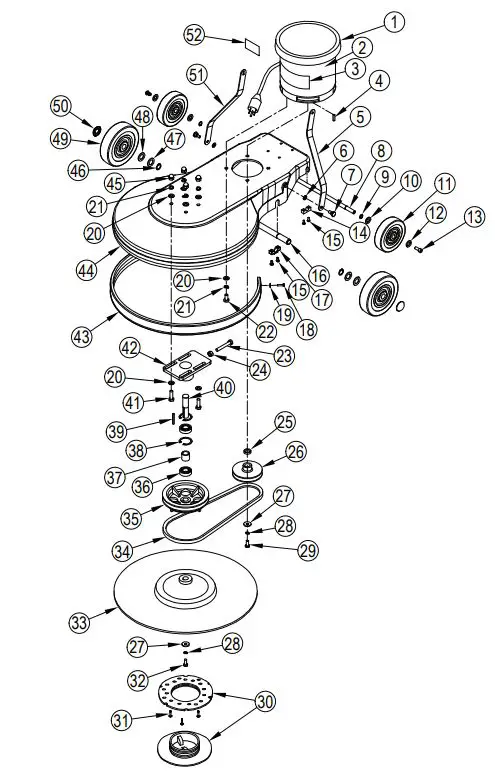
| Item | Ref. No. | Qty | Description | Item | Ref. No. | Qty | Description |
| 1 | ZD41000-1 | 1 | Motor,120v | 26 | VF52009G | 1 | Driving Pulley |
| [ ] | VF99926-2 | 1 | Carbon Brush (for ZD41000-1) | 27 | VF52021 | 2 | Washer, Plain,8x30x5 |
| [ ] | VF44204 | 1 | Rectifier (for ZD41000-1) | 28 | VF13519 | 2 | Washer, Lock, 8 |
| 2 | VF53110 | 1 | Label | 29 | VF14008 | 1 | Screw, 5/16”-18, Hex |
| 3 | VF41079CL | 1 | Label, Logo | 30 | VF99003A | 1 | Big Mouth |
| 4 | ZD40205 | 1 | Key, Motor | 31 | VA13484 | 3 | St4x12, Ph |
| 5 | VF53112 | 1 | Bracket, Left | 32 | GT13018 | 1 | Screw, M8x30, Hex |
| 6 | VF13514 | 2 | Washer, Plain, 8×16 | 33 | VF99024A | 1 | Pad Holder |
| 7 | VF53107 | 2 | Hex Screw, Bracket | 34 | VF14079B | 1 | Vee Belt |
| 8 | VF52011A | 1 | Axle, Transport | 35 | VF52004A | 1 | Driven Pulley |
| 9 | VF13520 | 2 | Retaining Ring, External, 12 | 36 | VF14075 | 2 | Bearing, 6004 2rs |
| 10 | VF50119 | 2 | Waving Washer, 12 | 37 | VF52006 | 1 | Spacer, Bearing |
| 11 | VF48202 | 2 | Wheel, 5” | 38 | VF14003 | 2 | Retaining Ring, Internal, X42 |
| 12 | VF13666 | 2 | Washer, Plain, 12 | 39 | VF52001 | 1 | Key, Driven Shaft |
| 13 | VF44012 | 2 | SCREW, M5 X 12.7 | 40 | VF52005 | 1 | Driven Shaft |
| 14 | GV40235 | 2 | Clamp Block, Axle | 41 | VF14007 | 4 | Hex Screw, M10x32 |
| 15 | VV13621 | 8 | Self-Tapping Screw, St5x20 | 42 | VF52007 | 1 | Mounting Plate, Driven Shaft |
| 16 | VF52010R | 1 | Front Axle | 43 | AS321203 | 1 | Bumper, Frame |
| 17 | VF47038 | 2 | Clamp Block, Axle | 44 | AS321201TP | 1 | Frame |
| 18 | VA13474 | 2 | Screw, M5x16 | 45 | VF14059 | 4 | Cap Nut, M10 |
| 19 | VF13474A | 2 | Washer, Plain, 5×16 | 46 | VF14004 | 2 | Retaining Ring, External, 19 |
| 20 | VF13517 | 12 | Washer, Plain, 8 | 47 | VF50123 | 2 | Washer, 19 |
| 21 | VF13518 | 8 | Washer, Lock, 8 | 48 | VF47027 | 2 | Waving Washer, 19 |
| 22 | VF13497 | 4 | Screw, 3/8”-16 | 49 | VF47055N | 2 | Wheel, 160mm |
| 23 | VF14009 | 1 | Hex Screw, M10x65 | 50 | VA96851 | 2 | Cap, Front Axle |
| 24 | VF14005 | 1 | Nut, M10 | 51 | VF531131 | 1 | Bracket, Right |
| 25 | VF52008 | 1 | Spacer | 52 | VF54029 | 1 | Notice Label |
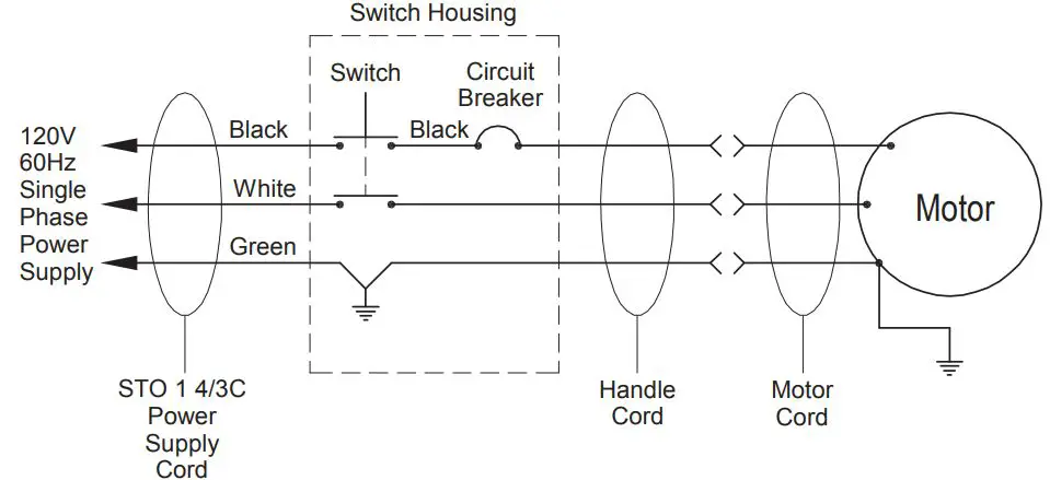
WIRING DIAGRAM
- 14600 21st Avenue North
- Plymouth, MN 55447-3408
- www.clarkeus.com
- Phone: 800-253-0367
- Fax: 800-825-2753
- ©2013 Nilfi sk-Advance, Inc.


