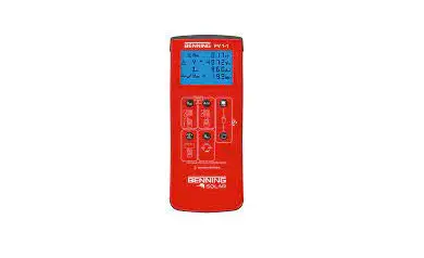
BENNING PV 1-1 Electrical Tester Instructions
Important information
![]() Before using the BENNING PV 1-1 please read the detailed operating manual (http://tms.benning.de/pv1-1) carefully. The BENNING PV 1-1 should only be used by suitably trained personnel.
Before using the BENNING PV 1-1 please read the detailed operating manual (http://tms.benning.de/pv1-1) carefully. The BENNING PV 1-1 should only be used by suitably trained personnel.![]() The connection to the PV generator is made exclusively in accord- ance with the connection figure of the operating manual. Disconnect not required safety tests leads from the BENNING PV 1-1.
The connection to the PV generator is made exclusively in accord- ance with the connection figure of the operating manual. Disconnect not required safety tests leads from the BENNING PV 1-1.
Before the measurement disconnected the PV array from the PV inverter!![]() The PV string under test must not exceed the maximum open-circuit voltage of 1000 V, the maximum short-circuit current of 15 A and the maximum DC power (P = Uoc x Isc) of 10 kW.
The PV string under test must not exceed the maximum open-circuit voltage of 1000 V, the maximum short-circuit current of 15 A and the maximum DC power (P = Uoc x Isc) of 10 kW.![]() The measurements are to be carried out on the individual PV string!
The measurements are to be carried out on the individual PV string!
It must be ensured that all switching devices and isolating devices are open and that all PV strings are isolated from each other.![]() Only test a single PV string, never test multiple strings and beware of parallel connections! High levels of capacitance within the circuit under test can cause high currents to flow and may damage the test instrument.
Only test a single PV string, never test multiple strings and beware of parallel connections! High levels of capacitance within the circuit under test can cause high currents to flow and may damage the test instrument.
Non-observiance will result in damage to the BENNING PV 1-1!![]() Disconnect the BENNING PV 1-1 from the test sample directly after the test.
Disconnect the BENNING PV 1-1 from the test sample directly after the test.![]() Do not touch the measuring probes! During insulating resistance measurements, high electric currents might be applied to the measuring probes.
Do not touch the measuring probes! During insulating resistance measurements, high electric currents might be applied to the measuring probes.![]() Do not touch any metal parts of the test object during measure- ment.
Do not touch any metal parts of the test object during measure- ment.![]() The PV generator must be isolated from the electric power supply! Neither the positive nor the negative pole of the PV generator must be earthed!
The PV generator must be isolated from the electric power supply! Neither the positive nor the negative pole of the PV generator must be earthed!![]() Via the 4 mm safety test leads, voltage measurements on mains supply circuits are possible. Via the 4 mm test sockets, the BENNING PV 1-1 must be used only in electric circuits of overvoltage category III with max. 300 V AC/DC for phase-to-earth measurements. For this please disconnect the PV 1-1 measuring leads from the PV test sockets before measuring.
Via the 4 mm safety test leads, voltage measurements on mains supply circuits are possible. Via the 4 mm test sockets, the BENNING PV 1-1 must be used only in electric circuits of overvoltage category III with max. 300 V AC/DC for phase-to-earth measurements. For this please disconnect the PV 1-1 measuring leads from the PV test sockets before measuring.![]() Before starting the unit, always check it for signs of damage. Do not use a damaged BENNING PV 1-1! m Only use safety measuring leads, which are supplied with the BENNING PV 1 1.
Before starting the unit, always check it for signs of damage. Do not use a damaged BENNING PV 1-1! m Only use safety measuring leads, which are supplied with the BENNING PV 1 1.![]() The BENNING PV 1-1 is intended for making measurements under dry ambient conditions only
The BENNING PV 1-1 is intended for making measurements under dry ambient conditions only
Switching the device ON/OFF
Press the ![]() -key and the
-key and the  -key simultaneously to switch the device ON or OFF. Without pressing a key, the device switches OFF automatically after approx. 1 minute (APO, Auto Power-Off).
Automatic measurement (Vo/c, Is/c, R150)
Attention:
Maximum DC power: P 10 kW, Vo/c 5 1000 V, Is/c 5 15 A
Do not make measurements at PV strings which are connected in parallel! 1. Carefully read and understand all safety notes under point
- “Important information”.
- Connect the BENNING PV 1-1 to the PV generator as shown, by means of the enclosed PV safety measuring leads and the red 4 mm safety test lead.
- The open-circuit voltage (Vo/c) is automatically displayed.
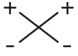
- In case of reversed polarity of the DC voltage, the symbol
 is displayed and the measurement will be blocked.
 - Use the Cl-key to select 250 V, 500 ast voltage. PV-module/ -string
- Press the
 key to automatically Automatic measurement (Ism) and insulation resistance (
 ).
).
Note: The red 4 mm safety measuring lead is required for the insulation resistance measurement.
 is displayed and the measurement will be blocked.
![]()
![]() Uoc x lac 5 10 kW
Uoc x lac 5 10 kW
Max.: lsc = 15 A,
Uoc = 1000 V, P = 10 kW
Disconnect all poles of the PV array from the inverter before testing!
Only test a single PV string, never test multiple strings and beware of parallel connections! High levels of capacitance within the circuit under test can cause high currents to flow and may damage the test instrument.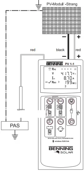
Null balance of the measuring leads, resistance (RPE)
- Connect the safety measuring leads to the red and black 4 mm test sockets of the BENNING PV 1-1.
- Hold the test probe tips together or connect together using the supplied crocodile clips.
- Press and hold the
 -key until an acoustic signal sounds and the
  -symbol is displayed.
 - The Null-value is stored when unit is switched off.
- To disable, press key until the symbol is removed from LC display.
Note: Max. measuring lead resistance: 10 Ohm
 -key until an acoustic signal sounds and the
  -symbol is displayed.
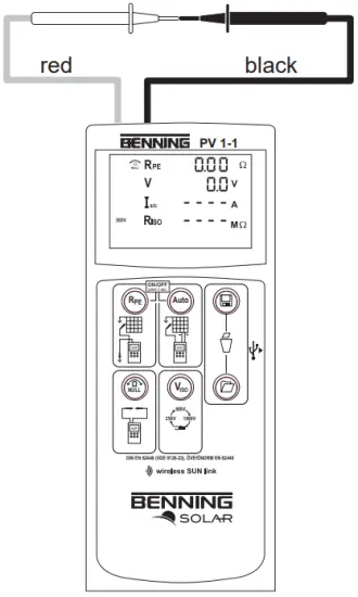
Protective conductor resistance (RPE)
- Connect the 4 mm safety measuring leads as shown.
- To make a single measurement (2 sec.), press and release the
 -key.
-key. - T make a continuous measurement, press and hold the key until the symbol
 is displayed continuously.
 - Press the -key to terminate the continuous measurement.
Option: 40 m measuring leads BENNING TA 5 part no. 044039
PV-module/ -string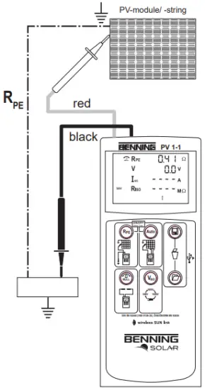
AC/DC current measurement
- Disconnect all safety measuring leads from the BENNING PV 1-1.
- Connect the BENNING CC 3 (option) current clamp adapter to the 4 mm test sockets.
- Select the 40 A range on the BENNING CC
- Press the null balance key (ZERO) of the BENNING CC 3 for approx. 2 seconds.
- Press the
 key on the BENNING PV 1-1 until the
  symbol AM is displayed.
 - The AC/DC current can be measured in single-wire live conductor.
 key on the BENNING PV 1-1 until the
 Option: BENNING CC 3 part no. 044038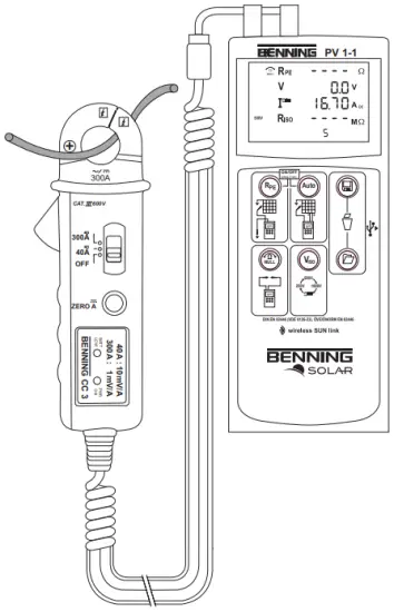
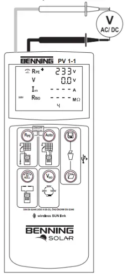
AC/DC voltage measurement
- Disconnect the PV safety measuring leads from the BENNING PV 1-1.
- Connect the red and black safety measuring lead as pictured.
- The BENNING PV 1-1 automatically measures the AC/DC voltage at the measuring probes.
- The polarity of the DC voltage is displayed by “+/-“. In case of AC voltage, “+/-” will be displayed alternately.
Max. CAT 111400 V

Measured value memory (200 display screens)
 -Store -Store | Store all measurements currently on the LC display. In the RECALL mode. the measuring results are called in reverse order. |
 Recall Recall | Recall the stored measured values on the LC display. |
 | Clear all results from memory. |
Reading out the measured value memory via the USB interface
- Install the driver and download program from the http://tms.benning.de/pv1-1 once.
- Disconnect all measuring leads from the BENNING PV 1-1.
- Connect the BENNING PV 1-1 to your PC by means of the USB connecting cable.
- Start the download program, select the COM p and click “Download”.
- Switch on the BENNING PV 1-1 and press the
 key for approx. 2 seconds.
 - Measured value download will start.
Preset limiting values
| Viso | Limiting value of insulating resistance |
| 250 V | 0.5 MΩ |
| 500 V/1000 V | 1.0 MΩ |
Measuring range
| Function | Range |
| RPE | 0 Ω – 199 Ω/30 V – 440 V I |
| Vo/c | 5 V – 1000 V |
| Isle | 0.5A- 15A |
| RIK) | 0.2 MΩ -199 MΩ |
| IAC/DC | 0.1 A- 40 |
Setting the date and time
- Turn off the BENNING PV 1-1.
- Press and hold the -key and then press simultaneously the key and the key of BENNING PV 1-1.
- The date format and time format is shown as follows: MM.DD = month (1-12). Day (1-31) YYYY = year HH.mm = hours (0-23).minutes (0-59) SS = seconds (0-59)
- Press the key to select a date field and time field
- A blinking field shows that this field can be set.
- With the
 -key and the -key, the value increases or decreases. With each change, the second field is set to zero.
 - Turn off the device to save the setting.
Note: If the BENNING PV 1-1 has established a radio connection to the BENNING SUN 2, the date/ time of the BENNING PV 1-1 will be synchronized automatically after 10 seconds to the date/ time of the BENNING SUN 2, if the device detects a deviation of more than 1 minute. BENNING SUN 2 (master) BENNING PV 1-1 (slave).
Setting the Auto Power Off (APO, Auto-Power Off)
- Turn off the BENNING PV 1-1.
- Press and hold the -key and then press simultaneously the -key and the key of BENNING PV 1-1. Keep the -key pressed.
- The LC display shows the first line “OFF” and in the second row the shutdown in minutes.
- Each press of the -key increases the shutdown time by one minute to 10 minutes.
- Then release the key to save the setting.
Radio connection to BENNING SUN 2 – wireless SUN link
The BENNING PV 1-1 is able to receive the measured values (insolation, PV mo-dule/ambient temperature and date/time stamp) of the insolation and temperature measuring instrument BENNING SUN 2 (optional) via radio connection. For this purpose, the BENNING PV 1-1 has to be coupled with the BENNING SUN 2 once. Typical radio range of the BENNING SUN 2 in open space: approx. 30 m Buildings/metal structures or interfering signals can reduce the radio range.
Coupling with insolation/temperature measuring instrument BENNING SUN 2
- Remove all electronic devices in direct vicinity
- Switch the BENNING PV 1-1 and the BENNING SUN 2 off.
- Press and hold the two ON/OFF keys of th- BENNING SUN 2.
- Press and simultaneously hold the key and the key of the BENNING PV 1-1.
- The BENNING PV 1-1 indicates the successful coupling by means of an acoustic signal and by displaying the serial no. of the BENNING SUN 2
- The “W/m2” symbol is shown on the LC display of the BENNING PV 1-1.
Decoupling from insolation/temperature measuring instrument BENNING SUN 2
- Remove all electronic devices in direct vicinity.
- Switch the BENNIN PV 1-1 off.
- Press and hold the key and the key of the BENNING PV 1-1 for approx. 10 seconds.
- The BENNING PV 1-1 indicates the decoupling from the BENNING SUN 2 by means of an acoustic signal and by clearing the LC display.
- The “RPE/O” symbol is shown on the LC display of the BENNING PV 1-1.
Activating/deactivating the radio transmission of the BENNING SUN 2
- Couple the BENNING PV 1-1 with the BENNING SUN 2.
- To activate/deactivate the radio transmission, press and hold the
 -key of the BENNING SUN 2 and simultaneously press the
  . A flashing triangle above the -key shows that the radio transmission has been activated.
 - If the BENNING PV 1-1 is within the radio range of the BENNING SUN 2, the measured insolation value (W/m2) is shown on the LC display of the BENNING PV 1-1.
- Besides the electric variables (Vo/c, Is/c, R150), AUTO measurement by means of the BENNING PV 1-1 additionally measures the insolation, the module and ambient temperature as well as the date/time stamp of the BENNING SUN 2.
- If the BENNING PV 1-1 is outside the radio range of the BENNING SUN 2, the “W/m2″ on the LC display starts flashing. Moreover, ” ” is shown on the LC display, if the measured insolation value is outside the measuring range.
 -key of the BENNING SUN 2 and simultaneously press the
  . A flashing triangle above the
 Note: If the BENNING PV 1-1 does not receive any radio signal from the BENNING SUN 2, the display indications are stored with the date/time stamp of the BENNING PV 1-1.
Error codes
| Error codes | Remedy |
 | The internal fuse has blown. Refer to chapter 9.5 in the opera-ting instructions for details. |
 | The electronic components of the BENNING PV 1-1 have reached the maximum admissible temperature. Disconnect the BENNING PV 1-1 from the object to be measured and let it cool down.
|
 | The DC short-circuit current has the maximum value of 15 A. The measurement has been stopped. |
 | The DC open circuit voltage has exceeded the maximum value of 1000 V. The measurement has been stopped.
|
Other error codes see detailed user guide on (http://tms.benning.de/pv1-1).


