Albeo ALB030 Indoor Lighting

 | BEFORE YOU BEGIN Read these instructions completely and carefully. Read and follow appropriate Lumination LED Luminaire Installation Guide for fixture installation. |
IMPORTANT SAFEGUARDS
WHEN USING ELECTRICAL EQUIPMENT, BASIC SAFETY PRECAUTIONS SHOULD ALWAYS BE FOLLOWED INCLUDING THE FOLLOWING: |
READ AND FOLLOW ALL SAFETY INSTRUCTIONS
SAVE THESE INSTRUCTIONS |
Ni-Cd or LiFePO4 Battery This equipment is not self-testing in conformance with the Life Safety Code, ANSI/NFPA 101 |
| |
RISK OF ELECTRIC SHOCK
| RISK OF FIRE
|
This device complies with Part 15 of the FCC Rules. Operation is subject to the following two conditions: (1) This device may not cause harmfulinterference, and (2) this device must accept any interference received, including interference that may cause undesired operation. CAN ICES-005 (A) / NMB-005 (A)
Note: This equipment has been tested and found to comply with the limits for a Class A digital device, pursuant to part 15 of the FCC Rules. These limits are designed to provide reasonable protection against harmful interference when the equipment is operated in a commercial environment. This equipment generates, uses, and can radiate radio frequency energy and, if not installed and used in accordance with the instruction manual, may cause harmful interference to radio communications. Operation of this equipment in a residential area is likely to cause harmful interference in which case the
user will be required to correct the interference at his own expense.
Installation Guide
Optional Installation:
Dimming or Control Interface
Follow instructions from appropriate Albeo LED Luminaire Installation Instructions to install optional control interfaces. Note: The fixture will not be controllable during emergency operation.
Emergency Lighting Fixture Operation
The emergency driver is capable of operating the LED load for a minimum of 90 minutes. The emergency driver battery recharge time is 32 hours. After installation, the battery should be allowed to charge.
This emergency lighting fixture should be tested regularly according to national and local code requirements. To test the emergency driver, remove AC power or press and hold the indicator test switch. Take standard precautions against static discharge while operating indicator test switch.
Prepare Electrical Wiring
 Electrical Requirements
The LED driver must be supplied with 120-277 VAC, 50/60 Hz per product label and connected to an individual properly grounded branch circuit, protected by a 15 or 20 ampere circuit breaker.
 Grounding Instructions
The grounding and bonding of the overall system shall be done in accordance with National Electric Code (NEC) Article 600 and local codes.
Installation of EBBM when Shipped with GE Fixture
Follow appropriate Albeo LED Luminaire Installation Instructions to install the fixture. Take standard precautions against static discharge during fixture installation.
Note: As received from the manufacturer, the luminaire may be partially energized.
Note: Per UL 924 and for best results, mount emergency lighting unit at a maximum of 35 feet.
Note: Mechanical attachment of EBBM to fixture required.
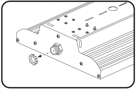
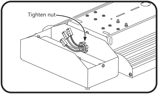
- Remove the conduit nut from the nipple adapter on the fixture

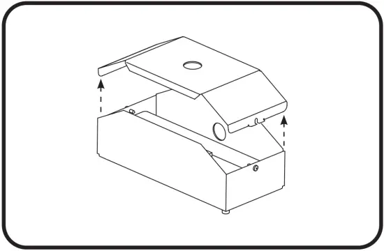
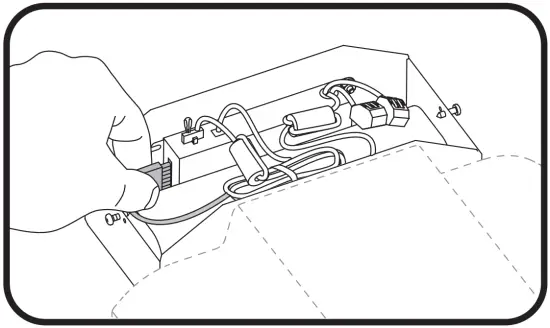
- Loosen two screws to remove the top cover of the EBBM unit

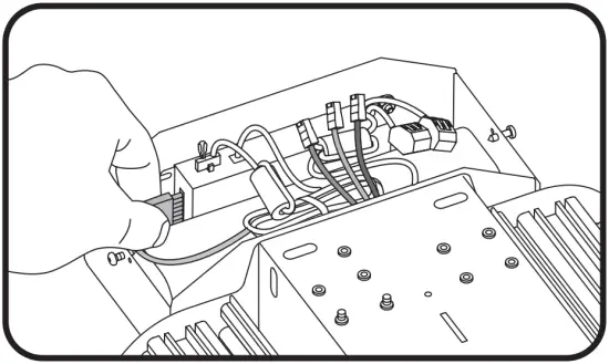
- Push fixture wires through EBBM unit side hole. Ensure ends are capped off. Mount EBBM unit to nipple and fasten conduit nut. Ensure that the EBBM is facing downwards

- Locate battery plug and push into the corresponding receptacle on the side of the charger. Proceed to the Electrical Connections section to complete.
Retrofit and Stand-Alone Installation
Note: As received from the manufacturer, the luminaire may be partially energized.
Note: Per UL 924 and for best results, mount emergency lighting unit at a maximum of 35 feet.
Note: When using a focusing optic, the installer may need to replace the installed lens with a different provided lens to meet the correct photometric requirements.
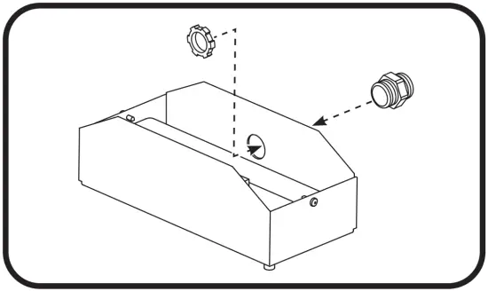
- Loosen two screws to remove the top cover of the EMBB unit.
- Install the provided standoff nipple adapter into the appropriate mounting hole.

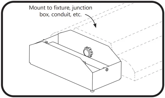
- Using the attached nipple adapter, mount the EBBM to an appropriate means of mounting (fixture, junction box, conduit, etc.). Ensure that the EBBM is facing downwards.
- Locate battery plug and push into the corresponding receptacle on the side of the charger. Proceed to the Electrical Connections section to complete.
Electrical Connections
- Follow Electrical Connections instructions from an appropriate Albeo LED Luminaire Installation Guide. Use UL listed fittings for wire protection.
- Refer to the applicable diagram below. Using UL listed 18-14 AWG twist-on wire connectors, connect the black (unswitched line), black (switched line), and white (neutral) input wires. Connect the ground wire to the green grounding wire as provided. Important: Make sure the necessary branch circuit wiring is available. An unswitched source of power is required. The emergency driver must be fed from the same branch circuit as the AC driver.
- Check that all internal plugs are connected to the battery charge unit. If a connector is loose, plug the connector into the appropriate receptacle on the battery charge unit.
- Seal any remaining hole in the EBBM cover with the provided plug. Reattach
Luminaire with EBBM with Two Power Drops
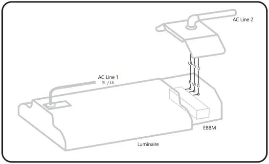
UL = Unswitched Line
SL = Switched Line
N = Neutral G = Ground
B = Black
W = White
O = Wire Connector
Switched Luminaire with EBBM with One Power Drop
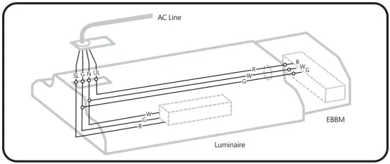
UL = Unswitched Line
SL = Switched Line
N = Neutral
G = Ground
B = Black
W = White
R = Red
O = Wire Connector
Unswitched Luminaire with EBBM with One Power Drop
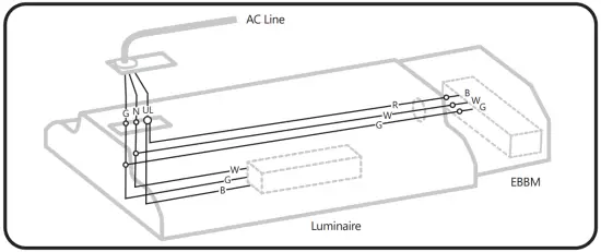
UL = Unswitched Line
SL = Switched Line
N = Neutral
G = Ground
B = Black
W = White
R = Red
O = Wire Connector
Luminaire with EBBM & Motion Sensor with Two Power Drops
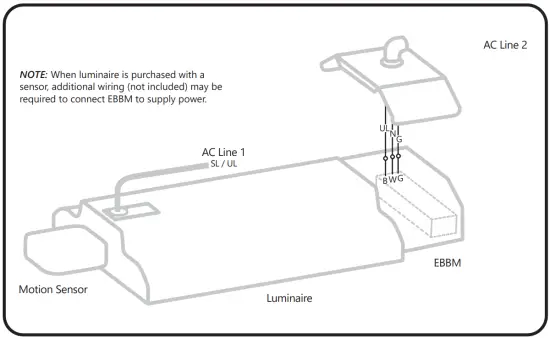
UL = Unswitched Line
SL = Switched Line
N = Neutral
G = Ground
B = Black
W = White
O = Wire Connector
Switched Luminaire with EBBM & Motion Sensor with One Power Drop
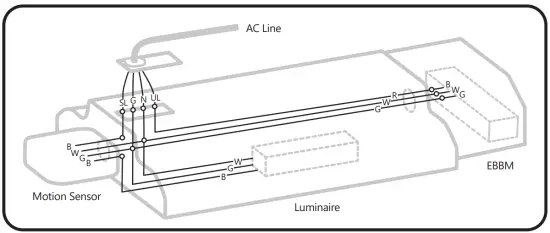
UL = Unswitched Line
SL = Switched Line
N = Neutral
G = Ground
B = Black
W = White
R = Red
O = Wire Connector
Unswitched Luminaire with EBBM & Motion Sensor with One Power Drop
UL = Unswitched Line
SL = Switched Line
N = Neutral
G = Ground
B = Black
W = White
R = Red
O = Wire Connector
Stand-Alone EBBM
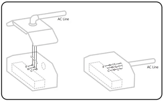
UL = Unswitched Line
N = Neutral
G = Ground
B = Black
W = White
O = Wire Connector
www.gecurrent.com
© 2021 Current Lighting Solutions, LLC. All rights reserved. GE and the GE monogram are trademarks of the General Electric Company and are used under license. Information provided is subject to change without notice. All values are design or typical values when measured under laboratory conditions.
ALB030 (Rev 04/02/2021)