![]() Live-8GT
Live-8GT
8-Port SOHO Gigabit Switch
Quick Setup Guide
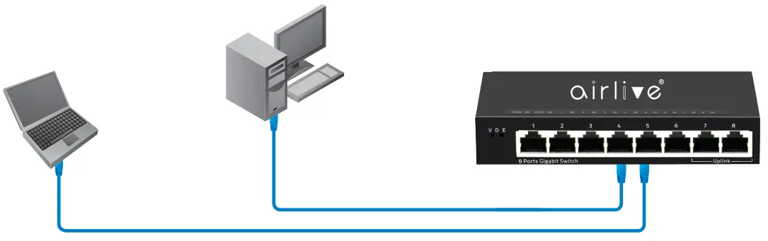
Installation Steps
Figure A
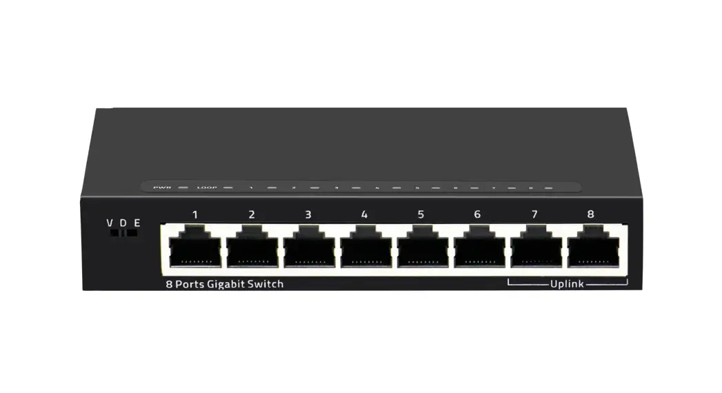
LED DEFINITIONS
| Power | Red ON | Power is on and normal. |
| Red Off | The switch is not receiving power. | |
| Loop | Green ON | Port loop. |
| Green Blinking | Port normal. | |
| Port | Green ON | Link connected. |
| Green OFF | Link disconnect. | |
| Green Blinking | Data transmisson. |
Mode Switch Control
| VLAN | Port isolation mode. In this mode ports 1~6 cannot communicate with each other and can only communicate with the Up-Link port 7/8. |
| Default | Normal mode. All ports can communicate with each other. Loop Support. |
| Extend | Extension mode. Data transmission distance can be extended to 250 meter at a transmission rate of 10Mbps Port 1~6 only. 1~6 Ports support 100M Speed reducation negotiation, 250 meters in 10Mbps mode, Port 7 and Port 8 as Uplink Port at 1000Mbps. |
Installation Step:
- Remove the switch and accessories from the package.
- Connect power to the switch. Make sure that “Power” LED is on.
- Check the Port LED indicator status. When a device is connected the port light up.
- For more product information visit www.airlive.com.
![]()


