![]()
EnPointe Fencing EP-W01 User Manual
BRAND ENPOINTE FENCING
MODEL EP-W01
The EP-W01 holds full modular approval. The OEM must follow the regulatory guidelines and warnings listed below to inherit the modular approval.
The EP-W01 modules are fencing specific radio modules, designed to interface with the EnPointe Fencing wireless fencing scoring systems. These modules are designed for
integration into scoring machines, repeater lights, and other sport fencing products, and can be used to allow other sport fencing manufacturers to access the EnPointe Fencing
proprietary data communications via the custom radio network.
These modules are not user-programmable, as they are issued from EnPointe Fencing fully programmed for the user’s needs. The radio communication core uses the Nordic nRF52833 SoC, with an ARM Cortex-M4F MCU, 512KB flash, 128KB RAM, embedded 2.4GHz multi-protocol transceiver, and u.FL connector for an external antenna.
EP-W01 FEATURES
— 64MHz Cortex-M4 with FPU
— 512KB Flash, 128KB RAM
— 2.4GHz radio transceiver
– Compatible with EnPointe Fencing radio protocol
– Can be configured for BLE or 802.15.4 communication
– 2Mbps, 1Mbps, 500kbps, 250kbps, 125kbps data rates
– Up to 8dBm TX power in EnPointe mode
– -92dBm RX sensitivity in EnPointe mode
— 1.7V to 5.5V supply voltage range
— Integrated DC-DC converter
— -40°C to 105°C operating temperature
— 68 pin LGA package, 10.2×15×1.9mm
– All 42 GPIO pins are accessible
— Flexible communication interfaces
– Full-speed 12Mbps USB 2.0 devices
– 32Mbps SPI master, 8Mbps SPI slave
– 1Mbps UART (with flow control)
– 400kbps I2C
– 13.56MHz Type 2 NFC-A tag (106kbps)
— Audio interfaces
– I2S for connection to speaker drivers and codecs
– PDM digital microphone interface
— 5 configurable 32-bit timers
— 3 real-time counters
— 16 PWM channels
— Analogue peripherals
– 64 level comparator with selectable reference
– 200ksps ADC with 8 single-ended or differential channels and programmable gain
– Temperature sensor
— Flexible firmware options for interfacing with EnPointe Fencing radio network
– Pin selection is customizable
– Port expander functionality is available
— Integrated touch-on sensing of other EnPointe products from any pair of analog pins
– Over-the-Air firmware updates using BLE mode
– Updates via other communication interfaces available
FOOTPRINT AND LGA PAD LOCATIONS
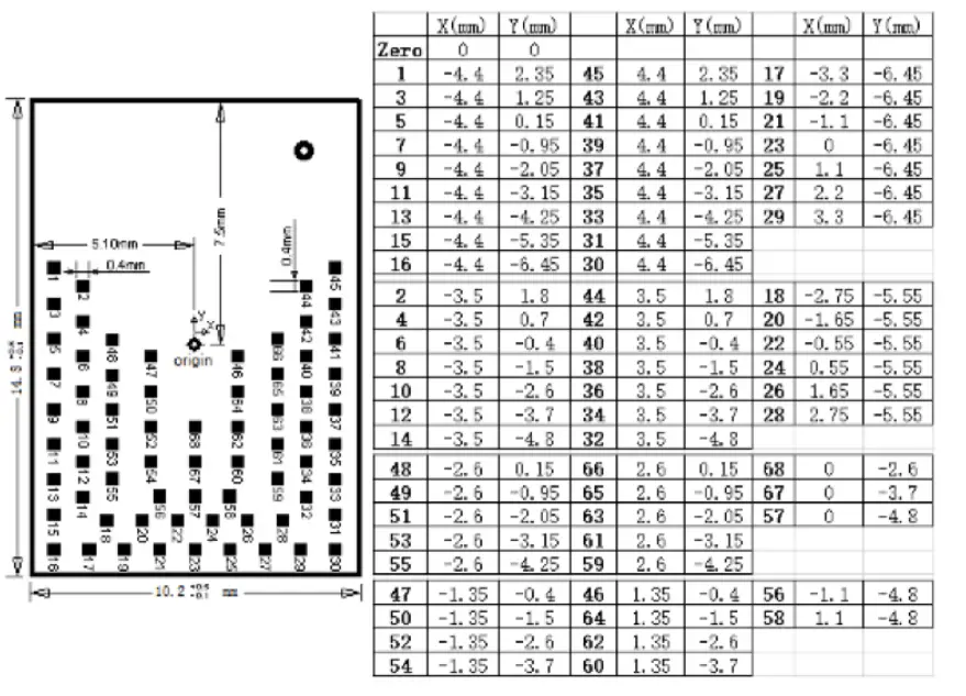
PINOUT
| Pin # | Pin Name | Pin Description | Pin # | Pin Nam | Pin Description |
| 1 | VSS | Ground | 35 | P0.15 | GPIO |
| 2 | VSS | Ground | 36 | P0.16 | GPIO |
| 3 | VSS | Ground | 37 | P0.17 | GPIO |
| 4 | VSS | Ground | 38 | P1.00 | GPIO |
| 5 | VSS | Ground | 39 | NC | Do not connect |
| 6 | NC | Do not connect | 40 | P0.18 | GPIO |
| 7 | P0.26 | GPIO | 41 | P0.13 | GPIO |
| 8 | P0.27 | GPIO | 42 | SWDCK | Reserved for programming; do not connect |
| 9 | P0.28/AIN4 | GPIO/Analogue input | 43 | STUDIO | Reserved for programming; do not connect |
| 10 | P0.29/AIN5 | GPIO/Analogue input | 44 | P0.22 | GPIO |
| 11 | P0.30/AIN6 | GPIO/Analogue input | 45 | VSS | Ground |
| 12 | P0.31/AIN7 | GPIO/Analogue input | 46 | NC | Do not connect |
| 13 | VSS | Ground | 47 | P0.24 | GPIO |
| 14 | VDD | Power supply | 48 | P0.19 | GPIO |
| 15 | VSS | Ground | 49 | P1.03 | GPIO |
| 16 | P0.00 | GPIO | 50 | NC | Do not connect |
| 17 | P0.01 | GPIO | 51 | P1.05 | GPIO |
| 18 | VSS | Ground | 52 | P1.09 | GPIO |
| 19 | VSS | Ground | 53 | P0.23 | GPIO |
| 20 | P0.03/AIN1 | GPIO/Analogue input | 54 | P1.08 | GPIO |
| 21 | P0.04/AIN2 | GPIO/Analogue input | 55 | P0.25 | GPIO |
| 22 | P0.02/AIN0 | GPIO/Analogue input | 56 | VDD | High voltage power supply |
| 23 | P0.05/AIN3 | GPIO/Analogue input | 57 | NC | Do not connect |
| 24 | P0.07 | GPIO | 58 | VBUS | 5V input for USB 3.3V regulator |
| 25 | P0.06 | GPIO | 59 | NC | Do not connect |
| 26 | P0.09/NFC1 | GPIO/NFC antenna connection | 60 | P0.21 | GPIO |
| 27 | P0.08 | GPIO | 61 | P1.04 | GPIO |
| 28 | VDD | Power supply | 62 | P0.20 | GPIO |
| 29 | P0.10/NFC2 | GPIO/NFC antenna connection | 63 | NC | Do not connect |
| 30 | VSS | Ground | 64 | P0.12 | GPIO |
| 31 | P1.01 | GPIO | 65 | P1.06 | GPIO |
| 32 | P1.02 | GPIO | 66 | P1.07 | GPIO |
| 33 | P0.14 | GPIO | 67 | D+ | USB D+ |
| 34 | P0.11 | GPIO | 68 | D- | USB D- |
The EP-W01 holds full modular approval. The OEM must follow the regulatory guidelines and warnings listed below to inherit the modular approval.
ANTENNA INFORMATION
The module has been designed to operate with the antennas listed below.
| Manufacturer | Model | Type | Connector | Peak gain |
| Pulse | W32921B0100 | Dipole | u.FL | 1dBi |
| LSR | 001-0014 | PIFA | u.FL | 2dBi |
Note: the OEM is free to choose another vendor’s antenna of like type and equal or lesser gain as an antenna appearing in the table and still maintain compliance. Reference FCC Part 15.204(c)(4) for further information on this topic.
FEDERAL COMMUNICATIONS COMMISSION (FCC) STATEMENT
You are cautioned that changes or modifications not expressly approved by the party responsible for compliance could void the user’s authority to operate the equipment. This equipment has been tested and found to comply with the limits for a Class B digital device, pursuant to part 15 of the FCC rules. These limits are designed to provide reasonable protection against harmful interference in a residential installation. This equipment generates, uses and can radiate radio frequency energy and, if not installed and used in accordance with the instructions, may cause harmful interference to radio communications. However, there is no guarantee that interference will not occur in a particular installation. If this equipment does cause harmful interference to radio or television reception, which can be determined by turning the equipment of and on, the user is encouraged to try to correct the interference by one or more of the following measures:
— Reorient or relocate the receiving antenna
— Increase the separation between the equipment and receiver.
— Connect the equipment into an outlet on a circuit different from that to which the receiver is connected.
— Consult the dealer or an experienced radio/TV technician for help.
This device complies with Part 15 of the FCC Rules. Operation is subject to the following two conditions:
- This device may not cause harmful interference, and
- This device must accept any interference received, including interference that may cause undesired operation of the device.
FCC RF RADIATION EXPOSURE STATEMENT
This equipment complies with FCC radiation exposure limits set forth for an uncontrolled environment. End-users must follow the specific operating instructions for satisfying RF exposure compliance. This transmitter must not be co-located or operating in conjunction with any other antenna or transmitter. This device is intended only for OEM integrators under the following conditions:
- The module may not be co-located with any other transmitter or antenna.
- The module must be used with the firmware provided by EnPointe Fencing Pty Ltd.
If the conditions above are met, further transmitter testing is not required. However, the OEM integrator is still responsible for testing their end-product for any additional compliance requirements required with this installed module. The end product with this module may be subject to FCC part 15 unintentional emissions test requirements.
Important note: If these conditions cannot be met (for example, certain laptop configurations or co-location with another transmitter), then the FCC authorization is no longer
considered valid and the FCC ID cannot be used on the final product. In these circumstances, the OEM integrator is responsible for re-evaluating the end product (including the transmitter) and obtaining a separate FCC authorization.
END PRODUCT LABELLING
Any device incorporating this module must include an external, visible, permanent marking or label which states: “Contains FCC ID: 2A3F8W01”.
MANUAL INFORMATION TO END USER
The OEM integrator must be aware not to provide information to the end-user regarding how to install or remove this RF module in the user’s manual of the end product which integrates this module. The end-user manual shall include all required regulatory information/warning as shown in this manual.
EnPointe Fencing Pty Ltd
5a Hartnett Close
Mulgrave Victoria
Australia 3170
[email protected]
enpointefencing.com![]()


