WESTERMO Ibex-RT-310 Series WLAN Client Bridge Access Point User Manual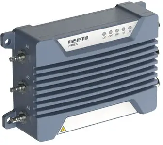
General Information
Legal Information
The contents of this document are provided “as is”. Except as required by applicable law, no warranties of any kind are made in relation to the accuracy and reliability or contents of this document, either expressed or implied, including but not limited to the implied warranties of merchantability and fitness for a particular purpose. Westermo reserves the right to revise this document or withdraw it at any time without prior notice.
Under no circumstances shall Westermo be responsible for any loss of data or income or any special, incidental, and consequential or indirect damages howsoever caused.
More information about Westermo can be found at www.westermo.com.
About This Guide
This guide is intended for installation engineers and users of the Westermo products.
It includes information on safety and regulations, a product description, installation instructions and technical specifications.
Software Tools
Related software tools are available at https://www.westermo.com/support/productsupport.
License and Copyright for Included FLOSS
This product includes software developed by third parties, including Free/Libre Open Source Software (FLOSS). The specific license terms and copyright associated with the software are included in each software package respectively. Please visit the product web page for more information.
Upon request, the applicable source code will be provided. A nominal fee may be charged to cover shipping and media. Please direct any source code request to your normal sales or support channel.
Safety and Regulations
Warning Levels
Warning signs are provided to prevent personal injuries and/or damages to the product. The following levels are used:
| Level of warning | Description | Consequence personal injury | Consequence material damage |
 WARNING WARNING | Indicates a potentially hazardous situation | Possible death or major injury | Major damage to the product |
 CAUTION CAUTION | Indicates a potentially hazardous situation | Minor or moderate injury | Moderate damage to the product |
 NOTICE NOTICE | Provides information in order to avoid misuse of the product, confusion or misunderstanding | No personal injury | Minor damage to the product |
 NOTE NOTE | Used for highlighting general, but important information | No personal injury | Minor damage to the product |
Table 1. Warning levels
Safety Information
Before installation:
Read this manual completely and gather all information available on the product. Make sure it is fully understood. Check that your application does not exceed the safe operating specifications for the product.
SAFETY DURING INSTALLATION
![]() The product must be installed and operated by qualified service personnel and installed into an apparatus cabinet or similar, where access is restricted to service personnel only. For Ibex products, outdoor installation is allowed.
The product must be installed and operated by qualified service personnel and installed into an apparatus cabinet or similar, where access is restricted to service personnel only. For Ibex products, outdoor installation is allowed.
During installation, ensure a protective earthing conductor is first connected to the protective earthing terminal (only valid for metallic housings). Westermo recommends a cross-sectional area of at least 4 mm2
Upon removal of the product, ensure that the protective earthing conductor is disconnected last.
HAZARDOUS VOLTAGE
![]() Do not open an energised product. Hazardous voltage may occur when connected to a power supply
Do not open an energised product. Hazardous voltage may occur when connected to a power supply
PROTECTIVE FUSE
The power supply wiring must be sufficiently fused.
![]() It must be possible to disconnect manually from the power supply. Ensure compliance to national installation regulations.
It must be possible to disconnect manually from the power supply. Ensure compliance to national installation regulations.
Replacing the internal fuse must only be performed by Westermo qualified personnel.
POWER SUPPLY CONNECTION![]() There are safety regulations governing the power source that can be used in conjunction with the product. Refer to chapter Interface Specifications.
There are safety regulations governing the power source that can be used in conjunction with the product. Refer to chapter Interface Specifications.
RADIO PRODUCTS
![]() Observe the usage limitations of radio products at filling stations, in chemical plants, in systems with explosives or potentially explosive locations.
Observe the usage limitations of radio products at filling stations, in chemical plants, in systems with explosives or potentially explosive locations.
The product may not be used in airplanes. Exercise particular caution near personal medical aids, such as pacemakers and hearing aids. Never perform work on the antenna system during a thunderstorm.
To fulfill human safety, a minimum separation distance of 20 cm or more should be maintained between the antenna of the product and personnel during operation.
HOT SURFACE
![]() Be aware that the surface of this product may become hot. When it is operated at high temperatures, the external surface may exceed Touch Temperature Limit according to the product’s relevant electrical safety standard.
Be aware that the surface of this product may become hot. When it is operated at high temperatures, the external surface may exceed Touch Temperature Limit according to the product’s relevant electrical safety standard.
This product complies with Touch Temperature Limits throughout its operational temperature range.
CORROSIVE GASES![]() If the product is placed in a corrosive environment, it is important that all unused connector sockets are protected with a suitable plug, in order to avoid corrosion attacks on the gold plated connector pins.
If the product is placed in a corrosive environment, it is important that all unused connector sockets are protected with a suitable plug, in order to avoid corrosion attacks on the gold plated connector pins.
CABLE TEMPERATURE RATING FOR FIELD TERMINAL WIRES![]() There may be a requirement on the minimum temperature rating of the cable to be connected to the field wiring terminals, see chapter Interface Specifications.
There may be a requirement on the minimum temperature rating of the cable to be connected to the field wiring terminals, see chapter Interface Specifications.
Care Recommendations
Follow the care recommendations below to maintain full operation of the product and to fulfill the warranty obligations:
- Do not drop, knock or shake the product. Rough handling above the specification may cause damage to internal circuit boards.
- Use a dry or slightly water-damp cloth to clean the product. Do not use harsh chemicals, cleaning solvents or strong detergents.
- Do not paint the product. Paint can clog the product and prevent proper operation.
If the product is used in a manner not according to specification, the protection provided by the equipment may be impaired.
If the product is not working properly, contact the place of purchase, the nearest Westermo distributor office or Westermo technical support.
![]() NOTE
NOTE
Devices not used shall be kept in the factory sealed moisture barrier bag. Open, unsealed devices should not be kept unpowered for more than 30 days.
Product Disposal
This symbol means that the product shall not be treated as unsorted municipal waste when disposing of it. It needs to be handed over to an applicable collection point for recycling electrical and electronic equipment.
By ensuring the product is disposed of correctly, you will help to reduce hazardous substances and prevent potential negative consequences to both the environment and human health, which could be caused by inappropriate disposal.
Figure 1. WEEE symbol for treatment of product disposal
Compliance Information
![]() REGULATORY NOTICE
REGULATORY NOTICE
Any changes or modifications shall be approved by the party responsible for compliance. If not, users could void the user’s authority to operate the equipment. Country code and antenna gain need to be set properly for correct functionality in the installed country.
Agency Approvals and Standards Compliance
| Approvals and Standards | |
| Climate |
|
| EMC |
|
| Mechanical(Shock and vibration) |
|
| Insulation (Coordination and test) |
|
| Radio communication |
|
| Safety |
|
United States – FCC
The enclosed product complies with Part 15 of the FCC Rules. Operation is subject to the following two conditions:
- this product may not cause harmful interference and
- this product must accept any interference received, including interference that may cause undesired operation.
To satisfy FCC RF exposure requirements for mobile transmitting devices, a separation distance of 20 cm or more should be maintained between the antenna of this product and persons during operation. To ensure compliance, operations at closer distances than this are not recommended.
This product has been tested and found to comply with the limits for a Class B digital device, pursuant to Part 15 of the FCC Rules. These limits are designed to provide reasonable protection against harmful interference in a residential installation. This product generates, uses and can radiate radio frequency energy and, if not installed and used in accordance with the instructions, may cause harmful interference to radio communications
However, there is no guarantee that interference will not occur in a particular installation. If this product does cause harmful interference to radio or television reception, which can be determined by turning the product off and on, the user is encouraged to try to correct the interference by one or more of the following measures:
- Reorient or relocate the receiving antenna
- Increase the separation between the unit and receiver
- Connect the product into an outlet on a circuit different from that to which the receiver is connected
- Consult the dealer or an experienced radio/TV technician for help
![]() NOTE
NOTE
This product contains FCC ID 2AEJD-103902-DT50RF.![]() NOTE
NOTE
The Ibex-RT-320-LV is registered for 4.9 GHz public safety band with the FCC ID 2AEJD-3623-0720
United States – AREMA
The product has been tested according to AREMA Part 11.5.1 environmental class J and C and AREMA Part 11.5.2 exposure class Internal.
Canada – IC
This product complies with Industry Canada’s license-exempt RSSs. Operation is subject to the following two conditions:
- This product may not cause interference.
- This product must accept any interference, including interference that may cause undesired operation of the product.
![]() NOTE
NOTE
This product contains the IC Certification number 9301A-103902DT50.![]() NOTE
NOTE
The Ibex-RT-320-LV is registered for 4.9 GHz public safety band with the IC Certification numbers 9301A-36230720
Certified Antennas for FCC and IC
The following antennas can be used with the product (the antenna type ID has to be set to the right value):
| Type | Part no. | Manufacturer | Gain | Chains | Antenna type ID |
| Dipole | F51-N | Tekfun | 2 GHz: 4.5 dBi max5 GHz: 7 dBi max | 1, 2, 3 | 1001 |
| Patch | SPA 2400/75/8/0/V | Huber & Suhner | 2 GHz: 8 dBi max | 1, 2, 3 | 1000 |
| Patch | SPA-5600/40/14/0/V_2 | Huber & Suhner | 5 GHz: 14 dBi max | 1, 2 | 1002 |
| Patch | SPA-5600/65/9/0/MIMO | Huber & Suhner | 5 GHz: 9 dBi max | 1, 2, 3 | 1003 |
| Shark | SPA-5600/45/12/10/V | Huber & Suhner | 5 GHz: 12 dBi max | 1, 2 | 1004 |
| Shark | SPA-5600/45/12/10/V | Huber & Suhner | 4 GHz: 12 dBi max | 1, 2 | 1009 |
Table 2. Certified antennas for FCC and IC
Simplified Declaration of Conformity
Hereby, Westermo declares that this product is in compliance with applicable EU directives and UK legislations. The full declaration of conformity and other detailed information is available at www.westermo.com/support/product-support.
![]()
Figure 2. The European Conformity and the UK Conformity Assessment markings
Product Description
Product Description
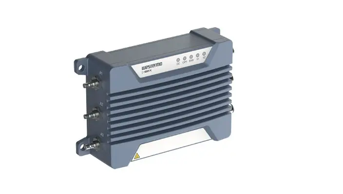
The Ibex-RT-310 and Ibex-RT-320 series can be configured as a WLAN Access Point, Client or Bridge. It is designed for onboard and infrastructure Wi-Fi installations in public transport and harsh environments. The 802.11 WLAN radio is operating at 2.4 GHz and 5 GHz frequency bands.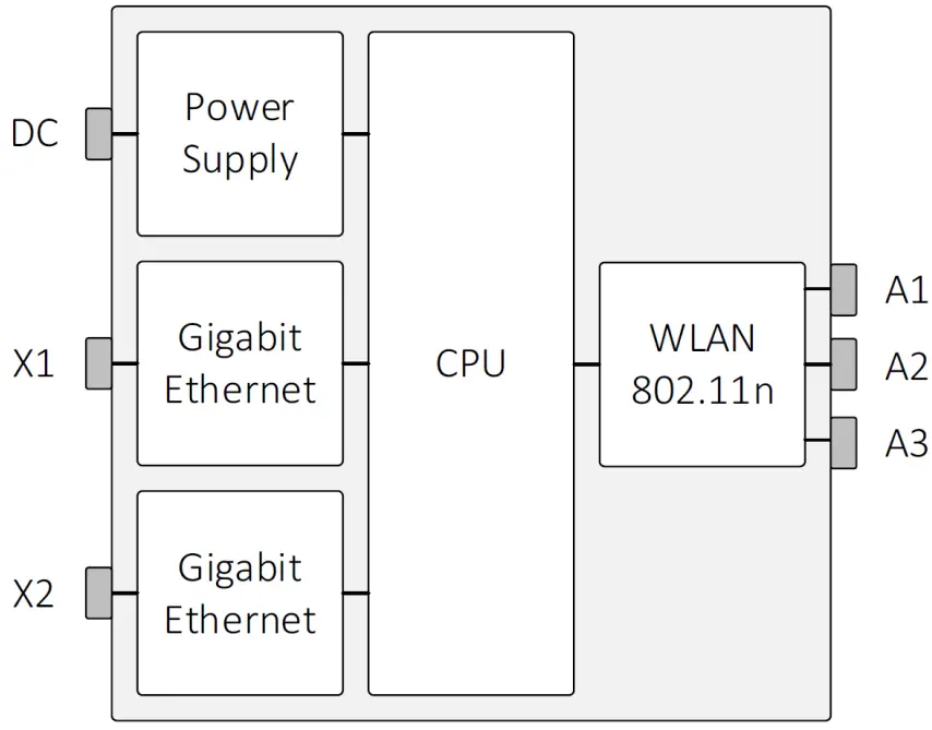
Figure 3. Ibex-RT-330 block diagram
The Westermo configuration management tool, WeConfig, can be used for discovery and basic configuration and maintenance. The configuration can be done via SNMP or via WebGUI. The status information is available in local LED status indicators, and through SNMP/WebGUI.
The Ibex-RT-310 och Ibex-RT-320 is designed to withstand tough environmental conditions and can be remotely managed using web browser or SNMP management tools. Integrating hardware, software and network design support tools, this router platform offers advanced capabilities, the lowest total cost of ownership and will create the most reliable and resilient networks.
The product is engineered to maintain uninterrupted data communication, even in exceptionally harsh environments. Tested and certified to withstand extreme temperatures, vibrations and shocks, these routers only use industrial grade components which contributes towards a market leading mean time between failure (MTBF), maximized service life, and reduced operational and life cycle costs.
Available models
| Art. no. | Model | Region | PoE Port | Rated current |
| 3623-071001 | Ibex-RT-310-LV EU | Europe | X2 | 24 VDC |
| 3623-071002 | Ibex-RT-310-LV NA | North America | X2 | 24 VDC |
| 3623-072001 | Ibex-RT-320-LV EU | Europe | X2 | 24 VDC |
| 3623-072002 | Ibex-RT-320-LV NA | North America | X2 | 24 VDC |
| 3623-072101 | Ibex-RT-320-HV EU | Europe | – | 72-110 VDC |
| 3623-072102 | Ibex-RT-320-HV NA | North America | – | 72-110 VDC |
Table 3. List of available models
Hardware Overview
Frontside Overview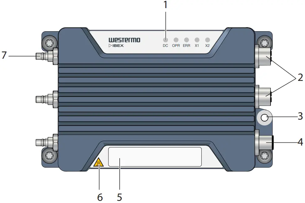
| No. | Description | ||
| 1 | LED indicators | 2 | Gigabit Ethernet ports X1 and X2 |
| 3 | Protective earth terminal | 4 | Power input DC |
| 5 | Frontside label | 6 | Warning symbol for surface temperatures above +60°C |
| 7 | Antenna ports A1 to A3 |
Table 4. Location of interface ports and LED indicators
Front Side Label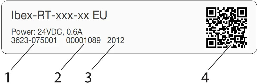
| No. | Description | Remarks |
| 1 | Article number | Example of article number |
| 2 | Serial number | Example of serial number |
| 3 | Manufacturing date | The Date Format is: YYWW YY = Manufacturing Year WW = Manufacturing Week |
| 4 | QR code | The data matrix is: AAAAAAAAARR-1-VV-SSSSSSSS-YYWW AAAAAAAAA = Article numberRR = Region codeVV = Product revision SSSSSSSS = Serial number YY = Manufacturing Year WW = Manufacturing Week |
Table 5. Front side label
Interface Ports View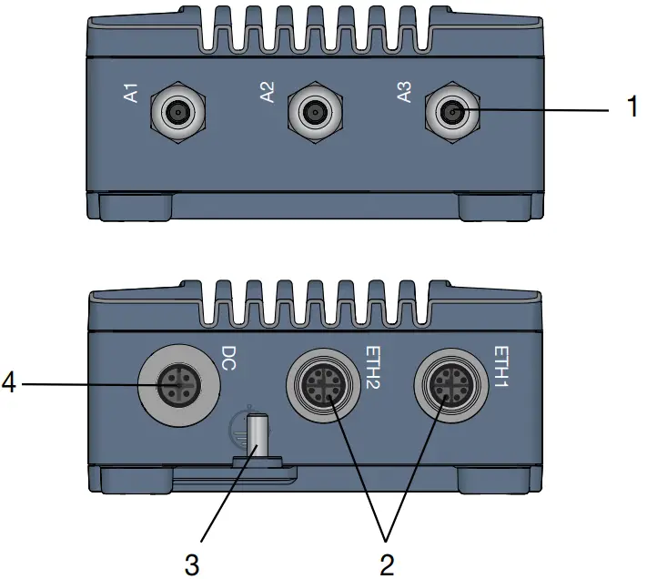
| No. | Description | No. | Description |
| 1 | Antennas | 2 | 1000Base-T |
| 3 | Grounding point | 4 | Power |
Table 6. Interface ports view
Connector Information
Power Input Connection
| Marking | Position | Direction | Description | |
| DC | 1 | +DC | Positive terminal | 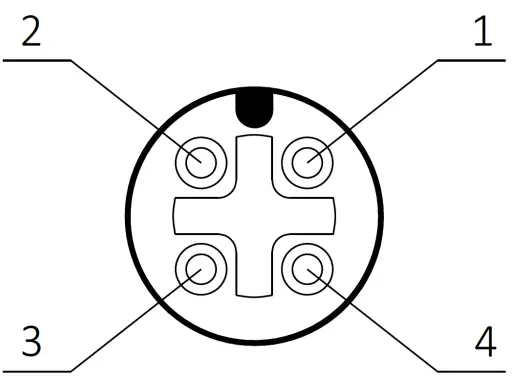 |
| 2 | – | |||
| 3 | -DC | Negative terminal | ||
| 4 | – | |||
| Housing | Shield | Chassis of product (ground) |
Table 7. M12 A-coded 4-pin male power connector according to IEC 61076-2-101
![]() NOTE
NOTE
If the product is powered by PoE, the protective dust cap which is part of the delivery must be closed to protect the power interface from water or dust ingress
Ethernet Ports
The product includes two Ethernet ports X1 and X2 which supports auto negotiated 10 Mbit/s, 100 Mbit/s and 1000 Mbit/s operation. Automatic MDI/MDIX crossover is supported for 10BASE-T, 100BASE-T, 1000BASE-T operation.
| Marking | Position | Direction | Description | |
| X1/X2 | 1 | In/Out | DA+ | 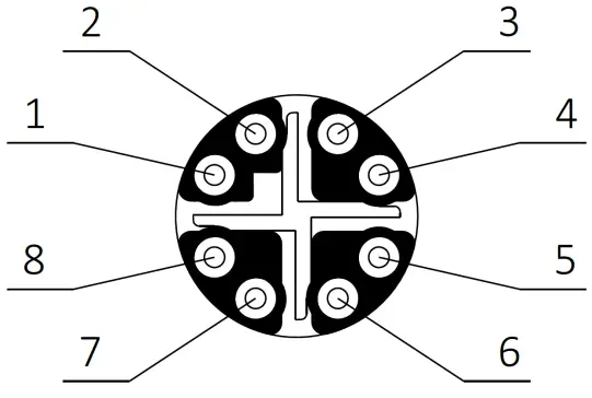 |
| 2 | In/Out | DA- | ||
| 3 | In/Out | DB+ | ||
| 4 | In/Out | DB- | ||
| 5 | In/Out | DD+ | ||
| 6 | In/Out | DD- | ||
| 7 | In/Out | DC- | ||
| 8 | In/Out | DC+ | ||
| Housing | Shield | Chassis of product (ground) |
Table 8. M12 X-coded 8-pin female Ethernet connector according to IEC 61076-2-109
| Position | Device mode A | Device mode B |
| 1 | +DC | |
| 2 | +DC | |
| 3 | -DC | |
| 4 | -DC | |
| 5 | -DC | |
| 6 | -DC | |
| 7 | +DC | |
| 8 | +DC |
Table 9. Ethernet PoE connection on X2 (LV-model only)
![]() NOTE
NOTE
PoE is supported on X2 for the LV product variant only.![]() NOTE
NOTE
If the Ethernet function is not used, the protective dust cap which is part of the delivery must be closed to protect the interface from water or dust ingress.
Antenna Ports
The antenna connectors are identified on the product with A1 to A3. QMA industrial standard connector is used.
A1 to A3 are used for WLAN communication. At least A1 must be connected to an external WLAN antenna. The antenna configuration is made through the software interface.
![]() NOTICE
NOTICE
Any unused antenna ports must be properly terminated with 50 Ohm, otherwise the product might be damaged when power is applied to a non-terminated antenna port.![]() NOTE
NOTE
To ensure specified IP protection, suitable QMA connectors/cables and terminations must be used.
LED Indicators
- DC

- OPR
- ERR
- X1
- X2

Figure 4. LED indicators
| LED | Description |
| DC | Power status |
| OPR | Operation status |
| ERR | Error status |
| X1 | Ethernet status for X1 port |
| X2 | Ethernet status for X2 port |
Table 10. LED indicators
![]() NOTE
NOTE
Refer to management guide for detailed LED status indication.
Dimensions
Dimensions are stated in mm and are regardless of variants.
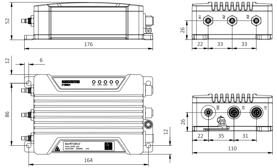
Figure 5. Dimensional drawing
Installation
Mounting
The product is fixed with the four fixing points located at the corners of the product. M5 or M6 screws are used for the fixation of the product. The screws are tightened with min. 3.0 Nm (fixing screw ISO 898/1, quality class 8.8).
![]() NOTICE
NOTICE
All four specified fixing points must be used for fixing. The installation surface should be flat to have all fixing points connected to the surface.
![]() NOTE
NOTE
For indoor installation, consider additional protection against dust to ensure proper heat dissipation.![]() NOTE
NOTE
For outdoor installation, consider additional protection against sun radiation, dust and dirt to optimize ambient temperature range.![]() NOTE
NOTE
Unused connectors must be covered by a protective cap (delivered with the product), tightened to the specified torque in order to fulfill the specified ingress protection code.
Factory Reset
To reset the product into factory default settings, a reset adapter is needed which is plugged into one of the Ethernet ports X1 or X2 during startup
| Art. no. | Description |
| 3623-0799 | Factory Reset Plug, X-coded |
Factory reset procedure
- Plug the factory reset adapter to one of the Ethernet interfaces.
- Power the product.
- Wait until factory reset adapter is detected. This is indicated by solid ORANGE OPR LED and RED ERR LED.
- Remove factory reset adapter within 15 seconds.
- Successful initiation of the factory reset is indicated by blinking ORANGE OPR LED and RED ERR LED.
Earth connection
For correct function, the earth connection at the grounding point needs to be properly connected to a solid ground. An M5 grounding screw at the housing is used for grounding. A short wire with a cross section of at least 4 mm2 shall be used. The grounding wire is set below the rip-lock washer. The nut is fixed for good reliable grounding contact. The tightening torque of the nut shall be 2.0 Nm.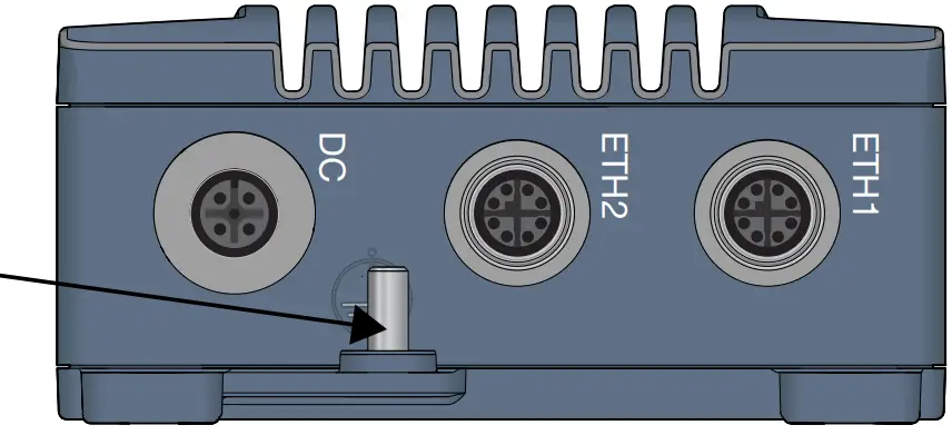
Figure 6. Earth connection
![]() NOTICE
NOTICE
Do not use equipment without protective earth connection.
Connection of Cables
Recommended tightening torque for the M12 connectors is 0.6 Nm. All M12 connections are screw connections.
When connecting the power cable, ensure that the pins are connected correctly before tightening the power cable to the unit.
![]() NOTE
NOTE
This product has no replaceable fuse and should be connected via an external fuse for protection.
Cooling
This product uses convection cooling. Make sure that it is installed so that the ambient temperature is within the specified temperature range, e.g. by avoiding obstruction of the airflow around the product.
It is recommended to install the product in areas where the natural convection airflow is not blocked and that there is enough spacing around the product.
Figure 7. Installation with reduced natural convection airflow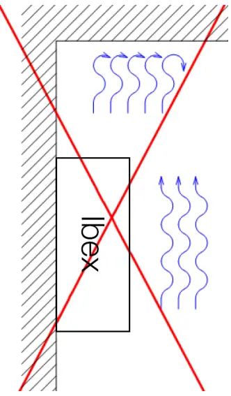
Figure 8. Installation with natural convection airflow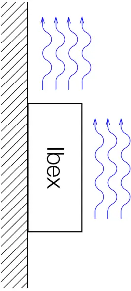
When operating the product at high ambient temperatures, it is recommended to mount the product to a metallic base plate to improve the heat dissipation. The base plate increases the surface to spread the heat.
Figure 9. Improved heat transfer based on fixing plate and natural convection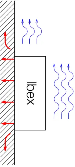
![]() NOTICE
NOTICE
Limited air flow is rising the product temperature and may lower the upper limit of the operating temperature range.![]() NOTICE
NOTICE
Temperature is dependent on the operational parameters, like RF output power, amount of traffic.![]() NOTICE
NOTICE
This product has integrated temperature sensors for monitoring the internal device temperatures. If temperature limits are exceeded, alarms are sent through the SW interface.![]() NOTICE
NOTICE
The operating conditions shall be ensured so that the normal operation does not cause temperature alarms. Improve installation conditions or RF parameters in case of any temperature alarms
Replacement of Product
Disconnect all cables and unscrew the product from the wall. Mount the replacement product and reconnect all cables, observing the instructions in Connection of Cables. MTTR (Mean Time To Repair), i.e. time for replacement of product is: < 10 minutes.
![]() HOT SURFACE
HOT SURFACE
Be aware that the surface of this product may become hot. When it is operated at high temperatures, the external surface may exceed Touch Temperature Limit according to the product’s relevant electrical safety standard.
This product complies with Touch Temperature Limits throughout its operational temperature range.
Specifications
Interface Specifications
| DC, Power port | ||
| Ibex-RT-310-LV and Ibex-RT-320- LV: | Ibe
x-RT-320-HV: | |
| Connector | M12 A-coded male | |
| Rated voltage | 24 VDC | 72 to 110 VDC |
| Operating voltage | 16 to 30 VDC | 50 to 138 VDC |
| Rated current | 0.6 A | 0.2 A |
| Rated frequency | DC | |
| Inrush current | 39 mA2s at 24 VDC | 4 mA2s at 72 VDC13 mA2 at 110 VDC |
| Startup current | 2 x rated current | |
| Polarity | Reverse polarity protected | |
| Redundant power input | No | |
| Conductor cross section (flexible) | > 0.5 mm² (AWG 20) | |
| Cable temperature rating | -40 to +70°C | |
| Shielded cable | Not required | |
| PoE (PoE powered product – Ibex-RT-310-LV and Ibex-RT-320-LV only on X2) | |
| Connector | M12 X-coded female |
| Device mode | A and B |
| Rated voltage | 48 VDC |
| Operating voltage | 37 to 57 VDC |
| Power classification | Class 3 |
| Ethernet TX | |
| Connector | M12 X-coded female |
| Electrical specification | IEEE std 802.3 |
| Data rate | 10 Mbit/s, 100 Mbit/s, 1000 Mbit/s, manual or auto |
| Duplex | Full or half, manual or auto |
| Transmission range | Up to 100 m with CAT5e cable or better |
| Cabling | Shielded cable CAT5e or better is recommended |
| Conductive chassis | Yes |
![]() NOTE
NOTE
The product is to be connected to internal Ethernet networks without exiting a facility and being subjected to TNVs. NOTICE
To avoid damages on the Ethernet interfaces, ensure that the far end side of the Ethernet cable shield itself is connected to protective earth.
| Antenna WLAN (A1, A2, A3) | |
| Connector | QMA female |
| Direction | Transmit and receive |
| Cabling | 50 Ohm coaxial cable and WLAN antenna required |
| Conductive chassis | Yes |
| WLAN interface | High power 3×3 MIMO 802.11n Access Point/Client |
| WLAN frequency bands | 2.400 to 2.4835 GHz, 4.940 to 4.990 GHz, 5.150 to 5.350 GHz, 5.470 to5.725 GHz, 5.725 to 5.850 GHz |
| Transmitting power Ibex-RT-310 | Max. conducted combined transmit power within the whole frequency range:802.11b/g/n, up to +18 dBm for all data rates 802.11a/n, up to +18 dBm for all data rates |
| Transmitting power Ibex-RT-320 | Max. conducted combined transmit power within the whole frequency range:802.11b/g/n, up to +27 dBm for all data rates 802.11a/n, up to +27 dBm for all data rates |
NOTICE
Depending on the installation country there are frequency/band restrictions and output power limitations.
NOTICE
Unused antenna port must be terminated with 50 Ohm terminations. NOTICE
To avoid damages on the antenna interfaces, ensure that the far end side of the antenna cable and/or the antenna itself is connected to protective earth.
Type Tests and Environmental Conditions
| Environmental phenomena | Basic standard | Description | Test levels |
| ESD | EN 61000-4-2 | Enclosure | Contact: ±6 kV Air: ±8 kV |
| Fast transients | EN 61000-4-4 | DC power port | ± 2 kV, direct coupling |
| Ethernet ports | ± 2 kV, capacitive coupling clamp | ||
| Antenna ports | |||
| Surge | EN 61000-4-5 | DC power port | L-E: ± 1 kV, 12 Ω, 9 µF, 1.2/50 µs L-E: ± 2 kV, 42 Ω, 0.5 µF, 1.2/50 µs L-L: ± 1 kV, 12 Ω, 9 µF, 1.2/50 µs L-L: ± 2 kV, 42 Ω, 0.5 µF, 1.2/50 µs |
| Ethernet ports | L-E: ± 1 kV, 2 Ω, 18 µF, 1.2/50 µs | ||
| Antenna ports | |||
| Power frequency magnetic field | EN 61000-4-8 | Enclosure | 300 A/m continues, DC, 16.7 Hz, 50 Hz,60 Hz |
| Pulsed magnetic field | EN 61000-4-9 | Enclosure | 300 A/m |
| Radiated RF immunity | EN 61000-4-3 | Enclosure | 20 V/m, 80% AM (1 kHz) at 80 MHz to 2.7 GHz3 V/m, 80% AM (1 kHz) at 2.7 GHz to 6 GHz30 V/m, PM 200 Hz square at 380 MHz to 385 MHz30 V/m, PM 200 Hz square at 390 MHz to 395 MHz |
| Conducted RF immunity | EN 61000-4-6 | DC power port | 10 V, 80% AM (1 kHz) from 0.15 to 80MHz |
| Ethernet ports | |||
| Antenna ports | |||
| Radiated RF emission | CISPR 16-2-3 | Enclosure | Class BFCC Part 15 B, Class B |
| Conducted RF emission | CISPR 16-2-1 | DC power port | Ibex-RT-310-LV and Ibex-RT-320-LV: Class B Ibex-RT-320-HV: Class A |
| Ethernet ports | |||
| Insulation resistance | EN 50155 | Power port (DC) to all other ports | > 100 MOhm |
| Dielectric strength | EN 50155 | Power port (DC) to all other ports | Ibex-RT-310-LV and Ibex-RT-320-LV: 750 VDC, 60 sIbex-RT-320-HV: 2250 VDC, 60 s |
| Temperatures | EN 60068-2-1EN 60068-2-2EN 60068-2-14 | Operational | -40 to +70°C (-40 to +158°F)a |
| Storage and transport | -55 to +85°C (-67 to +185°F) | ||
| Humidity | EN 60068-2-30 | Operational | 5-95% relative humidity |
| Storage and transport | |||
| Altitude | Operational | 3000 m | |
| MTBF | IEC TR 62380 | 370,000 hours | |
| Vibration | MIL STD 810,M514.7 (sine) | Operational | 5 to 10 Hz, 5.08 mm p-p10 to 200 Hz, 2 g20 sweep cycles in each axis, 0.9 octave/min |
| EN 60068-2-64(random) | Operational, endurance test | 11.44 m/s2 random, 5 to 150 Hz, 3 x 5 h2.3 m/s2 random, 5 to 2000 Hz, 3 x 4 h | |
| Shockb | EN 60068-2-27 | Operational | 100 m/s2, 30 ms, 3 x 6 shocks (half sine) |
| MIL STD 810, M516.7 | 20 g, 11 ms, 3 x 6 shocks (saw tooth) | ||
| Weight | 1100 gr | ||
| Degree of protection | EN 60529 | Enclosure | IP66c |
| Cooling | Convection | ||
| Pollution degree | EN 62368-1 | PD2 | |
| Conformal coating type | IPC-A-610 | Electronic modules | AR (Acrylic) |
Refer to “Safety and Regulations” chapter regarding touch temperature
b The power and Ethernet cables need to be fastened 200 mm or closer to the unit. The same recommendation applies to the Antenna cables. cProvided all connectors are connected with IP66 cabling or fitted with protective caps (delivered with the unit) and tightened to the specified torque
Table 12. Environmental and mechanical conditions
Abbreviations and Terms
| Abbreviation | Description |
| AM | Amplitude Modulation |
| AREMA | American Railway Engineering and Maintenance-of-Way Association |
| AWG | American Wire Gauge |
| BPSK | Binary Phase Shift Keying |
| CAT5e | Category 5 Enhanced Cable |
| CE | Conformité Européenne |
| CPU | Central Processing Unit |
| DC | Direct Current |
| EMC | Electromagnetic Compatibility |
| EN | European Standard |
| ERR | Error |
| ESD | Electro Static Discharge |
| ETSI | European Telecommunications Standards Institute |
| FCC | Federal Communication Commission |
| FLOSS | Free/Libre Open Source Software |
| HV | High Voltage |
| IEC | International Engineering Consortium |
| IC | Industry Canada |
| ID | Identification |
| I/O | Input / Output |
| IP | Ingress Protection |
| ISO | International Standardization Organisation |
| LAN | Local Area Network |
| LED | Light Emitting Diode |
| LV | Low Voltage |
| MIMO | Multiple Input, Multiple Output |
| MTBF | Mean Time between Failure |
| MTTR | Mean Time to Repair |
| OPR | Operation |
| PM | Pulse Modulated |
| PoE | Power over Ethernet |
| QMA | Quick-connect RF Connectors |
| QR | Quick Response |
| RF | Radio Frequency |
| TNV | Telephone Network Voltage |
| SN | Serial Number |
| SNMP | Simple Network Management Protocol |
| VPN | Virtual Private Network |
| WebGUI | Web Graphical User Interface |
| WeConfig | Westermo Configuration Tool |
| WEEE | Waste Electrical and Electronics Equipment |
| WLAN | Wireless Local Area Network |
Table 13. Abbreviations and terms
Revision Notes
| Revision | Date | Change description |
| Rev. H | 2022-12 | 2.5.2 Agency approvals updated; SRRC certificate added, removed old chapter 3.3. Rear Side Label. |
| Rev. G | 2021-10 | (User guide migrated to CMS tool), 2.2 Safety Information; information on cooling moved to chapter 4.5 Cooling, 2.5.1 Agency Approvals and Standards Compliance updated, 3.3.2 Front Side Label; callouts reversed order, 3.5 Led Indicatiors; illustration added, 4.2 Factory Reset moved from old chapter 3.6, 4,5 Cooling; illustrations updated. |
| Rev. F | 2021-06 | 3.4.2 Updated (D-code > X-code) |
| Rev. E | 2021-05 | Regulatory statements updated for public safety band in chapter 2.5.2, 2.5.4, 2.5.5 and table 13. Note in chapter 2.3 updated. |
| Rev. D | 2021-03 | Product illustrations updated to blue, text in illustrations removed, Westermo address updated, chapter 2.5.5 updated |
Support
Westermo Metallverksgatan 6, SE-721 30 Västerås, Sweden Tel +46 16 42 80 00 Fax +46 16 42 80 01
E-mail: [email protected]
www.westermo.com
![]()


