Honeywell C15W2 Series Basic Switch for Hazardous Locations User Guide

DESCRIPTION
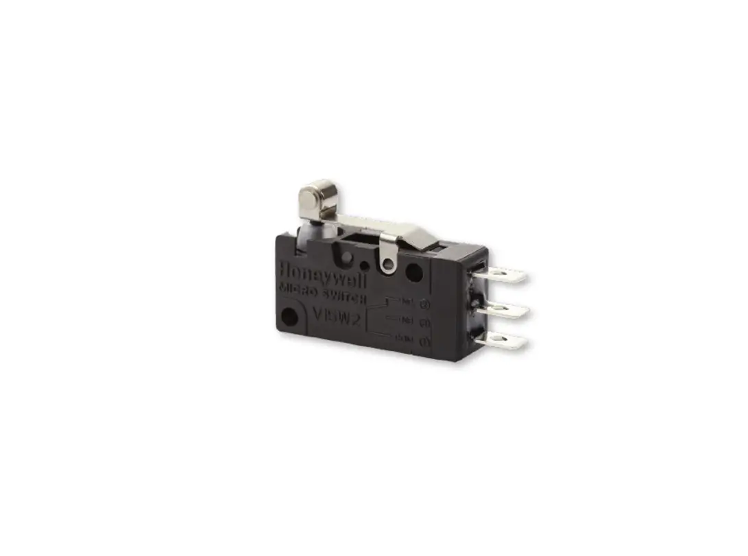
MICRO SWITCH V15W2 Series basic switches are precision snap-action contact mechanisms enclosed in plastic cases. Switch actuation triggers the mechanical closure of the switch’s contacts. The switches are approved for use in Zone 2 hazardous locations. While a small amount of arcing occurs between the switch contacts during contact closure, the switch is environmentally sealed so that flammable gases cannot enter into the switching cavity. This minimizes the chances of ignition of flammable gases in a hazardous atmosphere.
The ATEX and IEC Ex approvals are: Ex nC IIA T5 Gc for an ambient temperature range of -25 °C to +85 °C per EN/IEC 60079-0 and EN/IEC 60079-15 via certificates DEKRA 19ATEX0013U and IEC Ex DEK
17.0053U.
DIFFERENTIATION
- ATEX and IEC Ex approvals
- Wide variety of actuators, connections, operating and electrical characteristics
- More durable performance within a range of conditions
- Operates under many difficult/harsh environmental conditions
VALUE TO CUSTOMERS
- V-Basic switches for potential use in refrigeration units using alternatives for HFC and HCFCs, specifically targeting OEMs and Tier white goods manufacturers transitioning to lower GHA emission refrigerants (which tend to be more explosive) per EPA and other regulatory guidance
- Certified for use in ordinary locations via UL, cUL (North America), CQC (Asia-Pacific), and ENEC (Europe). Certified for use in hazardous locations via ATEX (Europe) and IEC Ex (International)
POTENTIAL APPLICATIONS
- Appliances (especially with new refrigerants)
- Valve actuators
- Commercial refrigeration
- Ice makers
- HVAC/R (furnace, refrigeration, ventilation)
FEATURES
- Approved for use in Zone 2 hazardous locations; ATEX and IEC Ex certifications
- IP67 equivalent
- UL, cUL, ENEC, and CQC certifications for ordinary (non-hazardous) locations
- 5 A electrical rating
- Longer service life: over one million mechanical operations
- Quick-connect terminals
- SPDT, SPNO, SPNC
- 100 gf, 200 gf operating forces
- Available with a variety of actuators
- Global package size acceptance
- Gold contacts are also available for controlling logic-level/low-energy circuits
PORTFOLIO
The MICRO SWITCH V15W2 Series basic switch is part of a broad Honeywell switch portfolio. Globally compliant and known worldwide for their compact and lightweight design, MICRO SWITCH
snap-action switches are designed for more accurate repeatability and extended life. To view the entire product portfolio, click here.
BASIC SWITCH FOR HAZARDOUS LOCATIONS, V15W2 SERIES
| TABLE 1. SPECIFICATIONS | |
| CHARACTERISTIC | PARAMETER |
| Circuitry | SPDT, SPNO, SPNC |
| Operating force | 100 gf, 200 gf |
| Termination | quick connect: 4,8 mm x 0,5 mm |
| Actuators | pin plunger, roller plunger other actuators/levers available for special order |
| Agency certification | UL, cUL, ENEC, CQC, ATEX, IEC Ex |
| Sealing | IP67 equivalent (terminals are sealed, but they are exposed so official rating is IP00) |
| Operating temperature | -25 °C to 85 °C [-13 °F to 185 °F] |
| Mechanical life (cycles) | 1,000,000 cycles min. @ 60 cycles/minute max. |
| Dielectric strength | 1000 Vac (RMS) for one minute between open contacts, leakage current <10 mA |
| Switch resistance (initial) | 50 mOhm max. |
| Insulation resistance | 100 mOhm min. (500 Vdc for one minute) |
| Contact material | Silver alloy |
| Housing material | PBT thermoplastic polyester |
| Sealing material | Silicone |
| TABLE 2. ELECTRICAL RATINGS | |
| CHARACTERISTIC | PARAMETER |
| UL/cUL electrical rating per UL 61058-1 | 5 A, 1/10 HP @ 125 Vac/250 Vac, 10,000 cycles |
| ENEC/CQC electrical rating per IEC 61058-1 and GB15091.1 | 5 A, 125 Vac/250 Vac, 50,000 cycles |
| TABLE 3. HAZARDOUS AREA CERTIFICATION |
| ATEX and IEC Ex per EN/IEC 60079-0 and EN/IEC 60079-15 Ex nC IIA T5 Gc -25°C < Tamb < +85°C |
Not all combinations of model code are available. Please contact your Honeywell provider/representative for assistance.
1These options have a three-month lead time for set up.
BASIC SWITCH FOR HAZARDOUS LOCATIONS, V15W2 SERIES
BASIC SWITCH FOR HAZARDOUS LOCATIONS, V15W2 SERIES
| TABLE 4. OPERATING CHARACTERISTICS | |||||||||
| Maximum Operate Force (g) | Minimum Release Force (g) | Maximum Pretravel mm | Minimum Overtravel mm | Maximum Differential Travel mm | Operate Point mm | ||||
| Operate Force Code | Operate Force Code | ||||||||
| Actuator Type | 100 | 200 | 100 | 200 | |||||
| LEVER POSITION A | |||||||||
| Pin Plunger | 100 | 200 | 15 | 40 | 1,2 | 1,0 | 0,4 | 14,8 ±0,4 | |
| 01 | Short Straight Lever | 90 | 180 | 11 | 29 | 2,0 | 1,1 | 0,6 | 15,5 ±0,6 |
| 02 | Standard Straight Lever | 60 | 110 | 7 | 19 | 3,0 | 1,5 | 0,9 | 15,6 ±1,0 |
| 03 | Long Straight Lever | 40 | 70 | 4 | 11 | 5,0 | 2,6 | 2,0 | 15,9 ±2,0 |
| 04 | Simulated Roller Lever | 65 | 125 | 8 | 21 | 2,8 | 1,5 | 1,0 | 19,1 ±1,0 |
| 05 | Roller Lever | 100 | 200 | 15 | 40 | 1,2 | 1,0 | 0,5 | 20,6 ±0,5 |
| 06 | Long Roller Lever | 70 | 130 | 9 | 23 | 2,5 | 1,3 | 0,7 | 20,8 ±1,0 |
| LEVER POSITION B | |||||||||
| Pin Plunger | 100 | 200 | 15 | 40 | 1,2 | 1,0 | 0,4 | 14,8 ±0,4 | |
| 01 | Short Straight Lever | 45 | 90 | 6 | 15 | 3,5 | 1,2 | 1,1 | 15,7 ±1,1 |
| 02 | Standard Straight Lever | 28 | 55 | 4 | 10 | 5,2 | 2,4 | 1,8 | 16,0 ±1,6 |
| 03 | Long Straight Lever | 18 | 35 | 2 | 6 | 9,0 | 4,5 | 3,0 | 16,5 ±3,3 |
| 04 | Simulated Roller Lever | 32 | 65 | 4 | 11 | 5,0 | 2,1 | 1,7 | 19,4 ±1,5 |
| 05 | Roller Lever | 58 | 115 | 7 | 19 | 3,0 | 1,2 | 0,9 | 21,0 ±0,9 |
| 06 | Long Roller Lever | 35 | 70 | 4 | 12 | 4,5 | 1,5 | 1,4 | 21,2 ±1,5 |
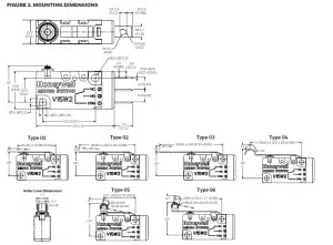
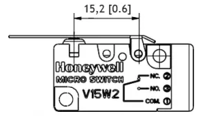 Lever Position A | 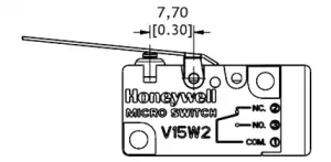 Lever Position B | ||||||||
ADDITIONAL MATERIALS
The following associated literature is available at sps.honeywell.com/ast:
- Product range guide
- Product installation instructions
- Application notes
- CAD drawings
- Product images
WARRANTY/REMEDY
Honeywell warrants goods of its manufacture as being free of defective materials and faulty workmanship during the applicable warranty period. Honeywell’s standard product warranty applies unless agreed to otherwise by Honeywell in writing; please refer to your order acknowledgment or consult your local sales office for specific warranty details. If warranted goods are returned to Honeywell during the period of coverage, Honeywell will repair or replace, at its option, without charge those items that Honeywell, in its sole discretion, finds defective. The foregoing is buyer’s sole remedy and is in lieu of all other warranties, expressed or implied, including those of merchantability and fitness for a particular purpose. In no event shall Honeywell be liable for consequential, special, or indirect damages.
While Honeywell may provide application assistance personally, through our literature and the Honeywell web site, it is buyer’s sole responsibility to determine the suitability of the product in the application.
Specifications may change without notice. The information we supply is believed to be accurate and reliable as of this writing. However, Honeywell assumes no responsibility for its use
FOR MORE INFORMATION
Honeywell Advanced Sensing Technolo- gies services its customers through a worldwide network of sales offices and distributors. For application assistance, current specifications, pricing, or the nearest Authorized Distributor, visit sps.honeywell.com/ast or call:
International +815 618 3231
USA/Canada +302 613 4491
WARNING
PERSONAL INJURY
DO NOT USE these products as safety or emergency stop devices or in any other application where failure of the product could result in personal injury.
Failure to comply with these instructions could result in death or serious injury.
WARNING MISUSE OF DOCUMENTATION
- The information presented in this product sheet is for reference Do not use this document as a product installation guide.
- Complete installation, operation, and maintenance information is provided in the instructions supplied with each product.
Failure to comply with these instructions could result in death or serious injury.


 39354 / Zw4003 Manual")


 39444/ Zw4103 Manual")


 39337 / Zw4103 Manual")


