
![]() INSTRUCTION MANUAL
INSTRUCTION MANUAL
MT500
ANALOGUE
INSULATION TESTER
SAFETY INFORMATION
- Read the following safety information carefully before attempting to operate or service the meter.
- To avoid damages to the instrument do not apply the signals which exceed the maximum limits shown in the technical specifications tables.
- Do not use the meter or test leads if they look damaged. Use extreme caution when working around bare conductors or bus bars.
- Accidental contact with the conductor could result in electric shock.
- Use the meter only as specified in this manual; otherwise, the protection provided by the meter may be impaired.
- Read the operating instructions before use and follow all safety Information.
- Caution when working with voltages above 60V DC or 30V AC RMS. Such voltages pose a shock hazard.
- Before taking resistance measurements or testing acoustic continuity, disconnect circuit from main power supply and all loads from the circuit.
SAFETY SYMBOLS
![]() Caution refer to this manual before using the meter.
Caution refer to this manual before using the meter.![]() Dangerous voltages.
Dangerous voltages.![]() Meter is protected throughout by double insulation or reinforced insulation.
Meter is protected throughout by double insulation or reinforced insulation.
When servicing, use only specified replacement parts. CE Comply with EN-61010-1
SPECIFICATIONS
3.1. General Information
Environment conditions:
- Installation Categories Ⅲ
- Pollution Degree 2
- Altitude up to 2000 meters
- Indoor use only
- Relatively humidity 80% max.
- Operation Ambient 0~40ºC
Maintenance & Cleaning:
- Repairs or servicing not covered in this manual should only be performed by qualified personnel.
- Periodically wipe the case with a dry cloth. Do not use abrasives or solvents on this instruments.
| Function | Range |
| Display | Large Analogue display |
| Measurement Range | 3Ω, 500Ω, 100MΩ/250V, 200MΩ/500V,400MΩ/1000V, 600V/ACV |
| Operating Temperature | 0°C to 40°C (32°F to 104°F) and Humidity below 80% RH |
| Storage Temperature | -10°C to 60°C (14°F to 140°F) and Humidity below 70% RH |
| Power source | DC9V (6×1.5V Size “AA” battery or Equivalent) |
| Dimensions | 200(L) x 92(W) x 50(H) mm |
| Weight | Approx 700g including battery |
| Accessories | Test leads, 6pcs battery, Carrying case, manual. |
3.2. Electrical Specifications
Accuracies are specified in the way:
±(…% of reading +…digits) at 23ºC±5ºC, below 80% RH.
OHMS
| Range | Resolution | Accuracy | Max. open Circuit Voltage | Max Circuit Current |
| 3Ω | 0.05Ω | ±3% | 4.5V | 250mA |
| 500Ω | 1Ω | 4.5V |
AC Voltage (40Hz~400Hz)
| Range | Resolution | Accuracy | Input Impedance | Overload Protection |
| 600V | 20V | ±5% | 1.2MΩ | 1000Vrms |
Meg OHMS
| Range | ±5% | ±10% | Terminal Voltage |
| 100MΩ/250V | 0.2MΩ~5MΩ | 5MΩ~100MΩ | 250V+10%~-0% |
| 200MΩ/500V | 0.5MΩ~10MΩ | 10MΩ~200MΩ | 500V+10%~-0% |
| 400MΩ/1000V | 1MΩ~20MΩ | 20MΩ~400MΩ | 1000V+10%~-0% |
| Range | Test Current | Short Circuit Current | |
| 1000MΩ/250V | 1mA | 250KΩ(load) | About 1.3mA |
| 200MΩ/500V | 500KΩ(load) | ||
| 400MΩ/1000V | 1MΩ | ||
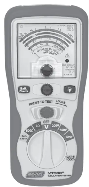
PARTS & CONTROLS
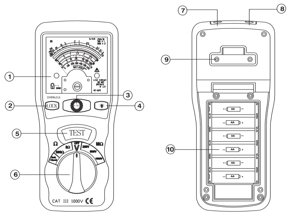
| 1. Point needle 2. Lock Button 3. 0-Adjust Button 4. Backlight Button 5. Test Button. | 6. Rotary Function switch 7. VΩ Jack 8. COM input jack 9. Pothook 10. Battery Cover |
HOW TO CONNECT TEST LEADS.
a) On MΩ Range: Connect the red test lead into the “VΩ” terminal and the black lead into the “COM” terminal.
b) On3Ω/500Ω and ACV Range: Connect the red test lead into the “VΩ” terminal and the black lead into terminal “COM”
INSULATION RESISTANCE MEASUREMENTS
6.1. Measurements at 200MΩ/500V
This is the voltage used for the majority of insulation resistance tests on normal installation requirement. To measure insulation resistance, press the test button to power on the tester. The point needle will displayed the insulation resistance. Section VII indicated that subdivision of large installations might be necessary because of the large number of parallel insulation resistance. In such a case, an installation may be divided into sections, each being separately tested. Each section must have not less than fifty outlets, an outlet being a switch, socket, lighting point etc. A switched socket counts as one outlet. The minimum acceptable insulation resistance is 1MΩ. For a large installation, the capacitance of the insulation will be high, and it will take longer for it to become charged by the direct testing voltage. Care must be taken not to take a reading until there is a steady reading, indicating that the charging process is complete.
Note: The charge stored in the insulation will be discharged automatically when the test button is released. Be careful not to turn the range switch knob whilst the test button s pressed, or the instrument will be damaged.
6.2. Lock power on Feature
For hands free operation a lock power on feature is incorporated on the press to test button. Set LOCK button to lock test voltage, Pressing it again will switch it off.
AC VOLTAGE MEASUREMENTS
- Set the range switch to ACV position
- Connect red test lead to “V Ω” terminal and black test lead to terminal “COM”.
- Connect test prods of test leads IN PARALLEL to the circuit being measured. 4. Read the voltage value on meter.
![]() MAJOR TECH (PTY) LTD
MAJOR TECH (PTY) LTD
South Africa![]() www.major-tech.com
www.major-tech.com![]() [email protected]
[email protected]
Australia![]() www.majortech.com.au
www.majortech.com.au![]() [email protected]
[email protected]![]()


