SONOS EN54-23 Beacons and Sounder Beacons Instruction Manual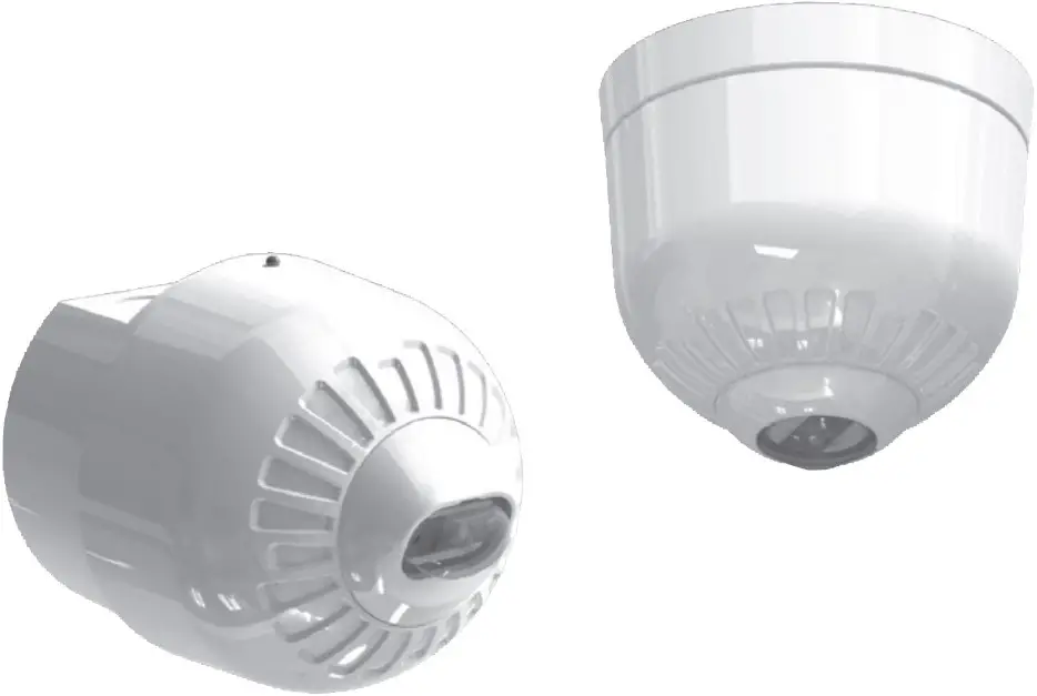
Fire Alarm Device: Beacon.
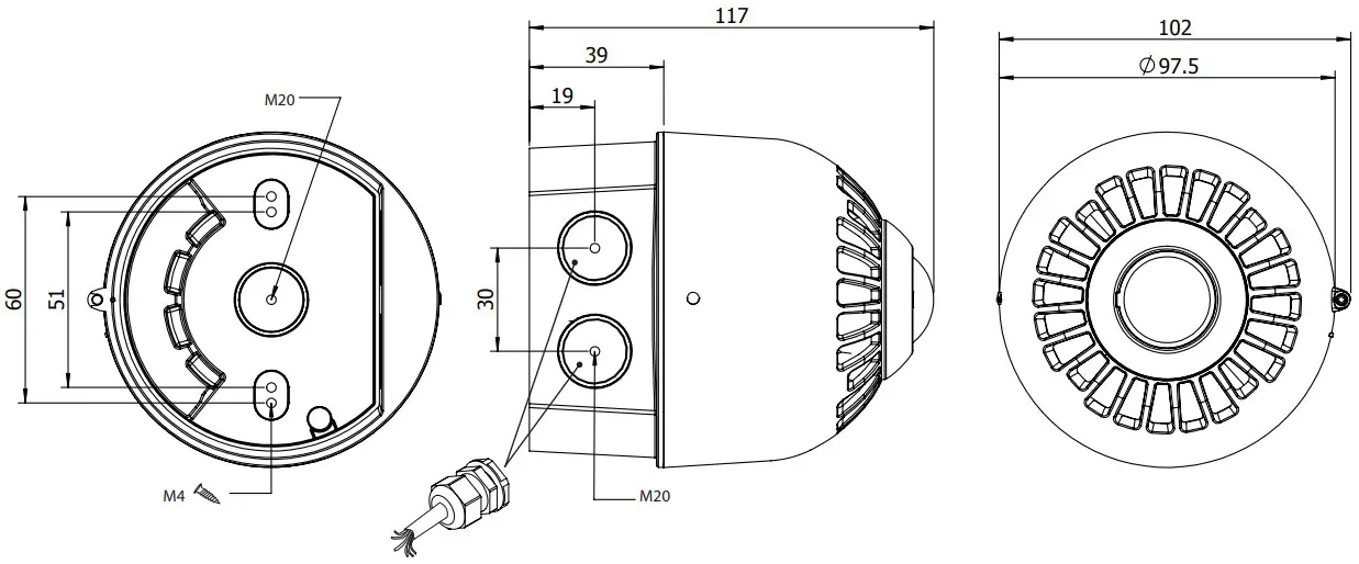
Type A: For indoor use (Shallow Base)
Type B: For outdoor use (Deep Base)
Technical Datatsheet ATS00001
| Head Type | Coverage Volume | CPR Number | LPCB Number |
| ESBA3000R | C-3-15 | 0832-CPR-F0007 | 717e/01 |
| ESBA3000W | C-3-15 | 0832-CPR-F0007 | 717e/02 |
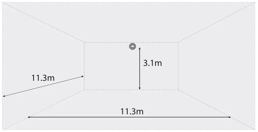
| ESBA4000R | W-3.1-11.3 | 0832-CPR-F0009 | 717e/03 |
| ESBA4000W | W-3.1-11.3 | 0832-CPR-F0009 | 717e/04 |
| Essential Characteristics | EN54-23:2010 Subclause |
| Duration of operation | Pass |
| Provision for external conductors | Pass |
| Flammability of materials | Pass |
| Enclosure protection | Pass |
| Access | Pass |
| Manufacturers adjustments | Pass |
| On-site adjustment behaviour | Pass |
| Requirements for software controlled devices | Pass |
| Coverage volume | Pass |
| Variation of light output | Pass |
| Minimum and maximum light intensity | Pass |
| Light Colour | White |
| Light temporal pattern and frequency of flashing | Pass 0.5Hz/1Hz |
| Marking and data | Pass |
| Synchronisation (Option with requirements) | Pass |
| Durability | Pass |
| Temperature Resistance | Pass |
| Humidity resistance | Pass |
| Shock and vibration resistance | Pass |
| Corrosion resistance | Pass |
| Electrical stability | Pass |
Shallow Base
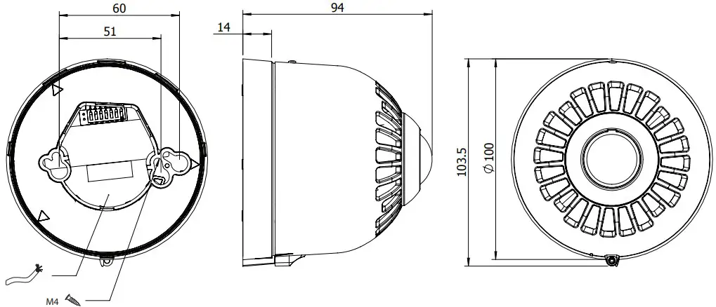
Ensure the lens of the device is pointing to the floor
Wall
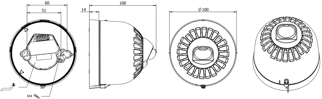
Deep Base
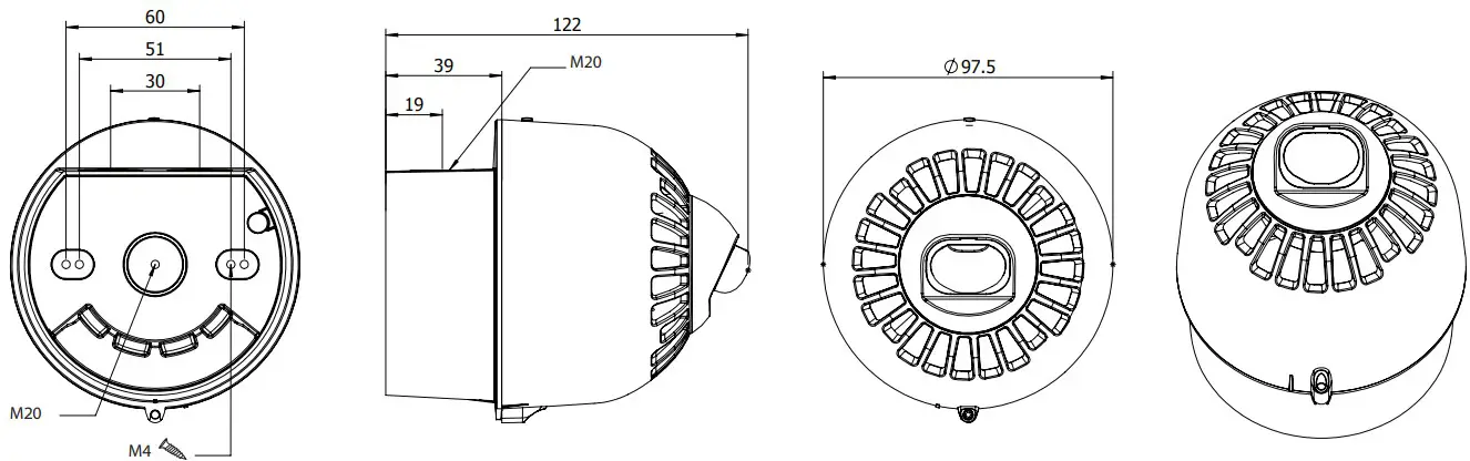
Ensure the lens of the device is pointing to the floor.
Ceiling
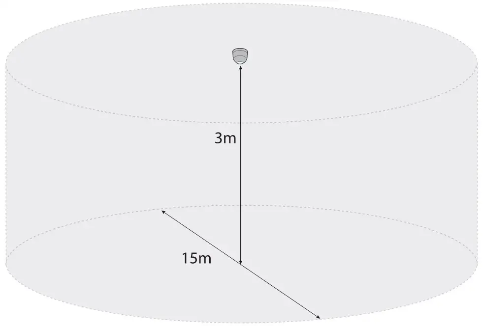
54-23 Coverage: C-3-15
Installation Manual
If required, the mechanism for locking the sounder to the base can be activated by removing the thin section of plastic shown in Fig. 1a with side cutters or a similar tool. To open a locked head, remove the small rubber bung from the hole on the side of the sounder, insert a tool into the hole and depress the clip whilst twisting the head. The O-ring and bung must be re-fitted to maintain the weatherproofing.
An alternative locking method is shown in Fig. 1b. Drive the hexagonal locking screw forward by turning a 1.5mm hexagonal key clockwise until the head is locked.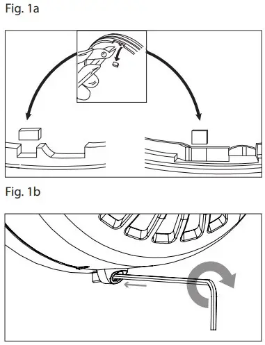
Wiring
| Line | Terminal Marking |
| Common Positive Supply IN | (3) IN+ |
| Beacon Negative Supply | (1) |
A separate earth terminal is provided on the deep base for connecting the screen or functional earth. On the shallow base, terminal 5 can be used for this purpose.
Flash rate
Switch 2 Flash rate: 0.5Hz =OFF/1Hz =ON (See Figure 2).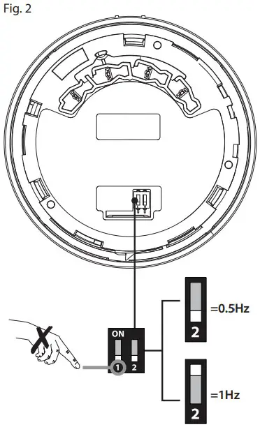
Technical Specification
| Supply Voltage Range | 17- 60Vdc |
| Switch on Surge @ 24Vdc | <1.2mA |
| Current: | |
| Alarm (Beacon) @ 24Vdc 0.5Hz | 20mA |
| Alarm (Beacon) @ 24Vdc 1Hz | 40mA |
| Beacon: | |
| Flash RateLight Temporal Pattern | • 55ms ON, 945mS OFF; frequency flashing 1 second (1Hz)• 55ms ON, 1945mS OFF; frequency flashing 2 seconds (0.5Hz) |
| Flash Colour | White |
| Coverage (ceiling) | C-3-15 (530m3) |
| Coverage (wall) | W-3.1-11.3 (395.84m3) |
| Environmental: | |
| Humidity | 5% to 95% |
| Temperature | -25°C to +70°C |
| Casing | High Impact Polycarbonate |
| IP Rating | Type A-IP21C (shallow base) Type B-IP33C (deep base) for EN54-3,EN54-23 installations with a cable gland (IP33C minimum)For other installations independently tested to IP65 (IP65 is not valid on EN54-3 and EN54-23 installations). |
| Synchronisation | Automatic |
![]() Products marked with this symbol cannot be disposed of as unsorted municipal waste in the European Union. For proper recycling, return this product to your local supplier upon the purchase of equivalent new equipment, or dispose of it at designated collection points. For more information see: www.recyclethis.info.
Products marked with this symbol cannot be disposed of as unsorted municipal waste in the European Union. For proper recycling, return this product to your local supplier upon the purchase of equivalent new equipment, or dispose of it at designated collection points. For more information see: www.recyclethis.info.
Klaxon Signals is a registered trademark of Texecom Ltd. © 2014
St. Crispin Way, Haslingden, BB4 4PW
Tel: +44 1706 234800
Email: [email protected] www.klaxonsignals.com
Pulse Alert is a trademark of Texecom Ltd.