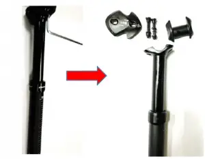
GIANT Switch Seatpost Instructions

Switch Seatpost
| Model Year: | MY18 |
| Model Name: | GIANT CONTACT SWITCH SEATPOST |
Parts List for After service
| Item | SKU | Description | Picture |
|
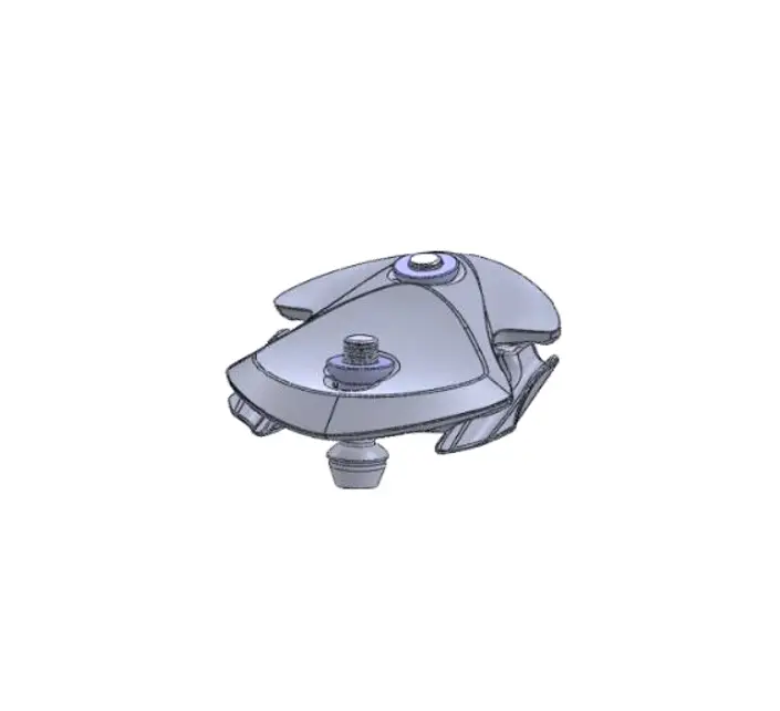
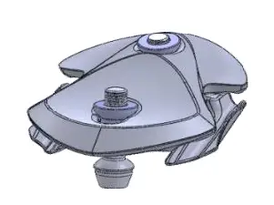
1 | 1729-CONTAC-803 | MY18 CONTACT SWITCH SEATPOST ACCESSARY TOP AND BOTTOM CLAMP W/TI BOLT(FOR CONTACT SWITCH S) |
|
| 1729-CONTAC-810 | MY18 CONTACT SWITCH SEATPOST ACCESSARY TOP AND BOTTOM CLAMP W/STL BOLT(FOR CONTACT SWITCH) | ||
|
2 |
1729-CONTAC-807 | MY18 CONTACT SWITCH SEATPOST ACCESSARY HORIZONTAL REMOTE LEVER W/WIRE AND ADJ BOLT | 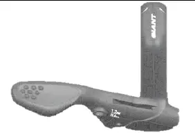 |
|
1729-CONTAC-814 |
MY18 CONTACT SWITCH SEATPOST ACCESSARY VERTICAL REMOTE LEVER W/WIRE AND ADJ BOLT | 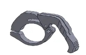
| |
|
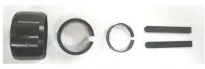
3 |
1729-CONTAC-808 |
MY18 CONTACT SWITCH SEATPOST ACCESSARY LOCKRING KIT(FOR CONTACT SWITCH S & CONTACT SWITCH) | 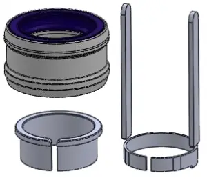 |
|
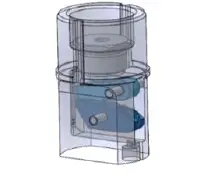
4 | 1729-CONTAC-804 | MY18 CONTACT SWITCH SEATPOST ACCESSARY AIR DAMPER(ALLOY) 100MM TRAVEL(FOR CONTACT SWITCH S) |
|
| 1729-CONTAC-805 | MY18 CONTACT SWITCH SEATPOST ACCESSARY AIR DAMPER(ALLOY) 125MM TRAVEL(FOR CONTACT SWITCH S) | ||
| 1729-CONTAC-806 | MY18 CONTACT SWITCH SEATPOST ACCESSARY AIR DAMPER(ALLOY) 150MM TRAVEL(FOR CONTACT SWITCH S) | ||
| 1729-CONTAC-811 | MY18 CONTACT SWITCH SEATPOST ACCESSARY AIR DAMPER(STEEL) 100MM TRAVEL(FOR CONTACT SWITCH) | ||
| 1729-CONTAC-812 | MY18 CONTACT SWITCH SEATPOST ACCESSARY AIR DAMPER(STEEL) 125MM TRAVEL(FOR CONTACT SWITCH) | ||
| 1729-CONTAC-813 | MY18 CONTACT SWITCH SEATPOST ACCESSARY AIR DAMPER(STEEL) 150MM TRAVEL(FOR CONTACT SWITCH) | ||
|
5 |
1729-CONTAC-809 | MY18 CONTACT SWITCH SEATPOST ACCESSARY BOTTOM LOCK MOUNT(FOR CONTACT SWITCH S & CONTACT SWITCH) |
|

Parts List for Gear
| Item | SKU | Description | Picture |
|
1 |
150000073 |
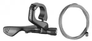
CONTACT SWITCH SEATPOST 1X LEVER AND CABLE SET |
|
|
150000074 |
CONTACT SWITCH SEATPOST 2X LEVER AND CABLE SET | 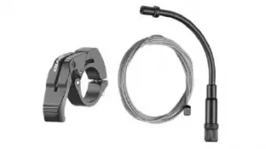 | |
|
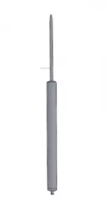
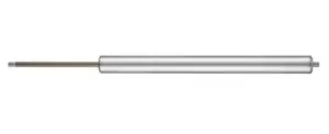
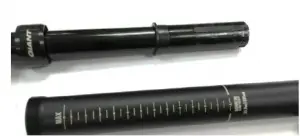
2 | 150000075 | CARTRIDGE FOR MY18 GIANT CONTACT S AND CONTACT SWITCH 350MM |
|
| 150000076 | CARTRIDGE FOR MY18 GIANT CONTACT S AND CONTACT SWITCH 395MM | ||
| 150000077 | CARTRIDGE FOR MY18 GIANT CONTACT S AND CONTACT SWITCH 440MM | ||
|
3 |
150000082 |
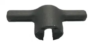
CARTRIDGE REMOVAL & INSTALLATION TOOL FOR MY18 CONTACT S AND CONTACT SWITCH SEATPOST |
|
Tool list
| Item | Description | Picture |
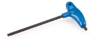
| 1 | 5mm Allen key |
|
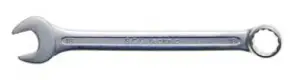
| 2 | 18mm wrench |
|
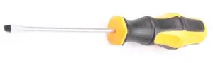
| 3 | Flathead screwdriver | |
| 4 | Mounting tool (Shimano TL-BH61 or other tools which can hold the inner rod of the cartridge) |  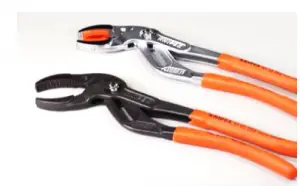 |
| 5 | Neutral assembly grease |  |
| 6 | Lower cap removal tool | 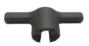 |
Disassembly procedure
| Step | Description | Picture |
| 1.1 | Disassemble the saddle clamp unit with a 5 mm Allen key |
|
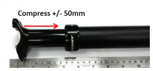
| 1.2 | Compress the seatpost by pulling the trigger with an inner cable and simultaneously pushing the stanchion +/- 50mm inwards. | 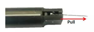 |
| ||
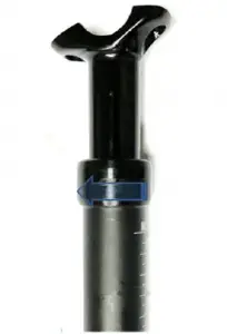
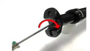
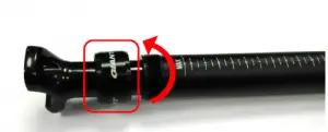
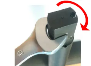
| 1.3 | Open the lower cap by turning counter clockwise with a 18mm wrench. | 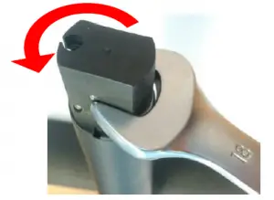 |
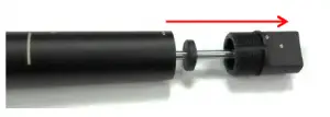
| 1.4 | Pull the lower cap out of the main seatpost shaft. Note: The lower cap stays attached to the internal rod. |
|
| Step | Description | Picture |
| 1.5 | Use a flathead screwdriver to detach the cartridge from the top of the seatpost head by turning in clockwise direction. |
|
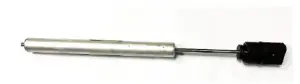
| 1.6 | Pull out the internal cartridge |
|
| 1.7 | Open the top cap by turning counter clockwise. |
|
| 1.8 | Pull out the inner stanchion from the main shaft. |
|
| 1.9 | Take off the top cap, sliders from the seatpost stanchion. |
|
| 1.10 | Clean the stanchion and main shaft with a dry clean cloth |
2. C artridge replacement
| Step | Description | Picture |
| Disassembly | ||
| 2.1 | Use a tool with a sharp point to pull out the rubber bumper from the lower cap. | 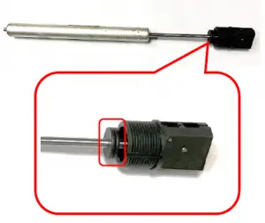 |
| 2.2 | Slide the special lower cap removal tool over the rod of the internal unit until it fits properly on the hexagon shape inside the lower cap. Hold the tool firmly and turn the lower cap counter clockwise to remove it from the rod. | 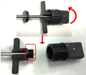 |
| 2.3 | Use a fixture (for example Shimano TL- BH61) to hold the inner rod of the cartridge in a vice. Loosen the nut by turning it counter clockwise and take it off together with the rubber bumper. | 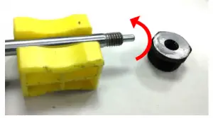 |
| Step | Description | Picture |
| Assembly | ||
|
2.4 | Slide the rubber bumper over the inner rod and tighten the nut by turning clockwise. (2Nm) Make sure the threads of the nut are facing outwards. | 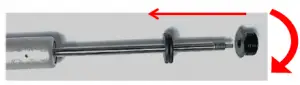 |
| 2.5 | Assemble the lower cap on the nut. Tighten it firmly by holding the nut the specific tool while turning the lower cap clockwise. | 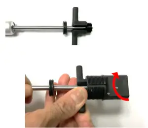 |
| 2.6 | Place the cartridge into the main shaft of the seatpost. | 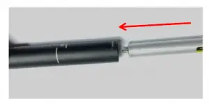 |
| 2.7 | Press the seatpost stanchion approximately 50mm inward. | 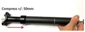 |
| Step | Description | Picture |
| 2.8 | Use a flathead screwdriver to tighten the cartridge in the seatpost head (turn counter clockwise). | 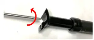 |
| 2.9 | Screw the lower cap into the main shaft of the seatpost and tighten it firmly clockwise with a 18mm wrench (5Nm) |
|
3. Top cap, dust seal and slider set assembly
| Step | Description | Picture |
| 3.1 | Top cap with dust seal and slider set | 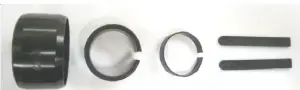 |
| 3.2 | Assemble the top cap on the stanchion in the following sequence: 1. Top cap with dust seal 2. Slider ring 2a. Place the slider ring inside the top cap. Note: Be careful not to damage the rubber seal in the dust cap while sliding it over the stanchion. | 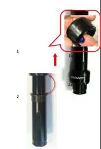 |
| Step | Description | Picture |
| 3.3 | 1. Place the side sliders inside the grooves on both sides of the stanchion. 2. Mount the round slider on the bottom of the stanchion, make sure it is secured properly in the designated profiles in the stanchion. | 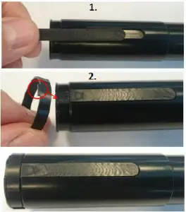 |
| 3.4 | Apply some neutral assembly grease on the inside of the main shaft and on the stanchion. | 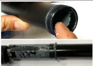 |
| 3.5 | Insert the stanchion in the main shaft. Make sure that the rear side of the seatpost head is at the side of the main shaft (with the insertion marking). Apply grease 2cc between top cap and Slider ring. | 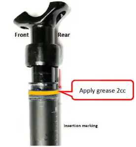 |
| Step | Description | Picture |
| 3.6 | Secure the top cap by mounting it in clockwise direction onto the threads on the main shaft. Tighten it firmly by hand. |
|
| 3.7 | Assemble the inner cartridge as described at point 2.6 to 2.9 |